-
Recent Posts
Recent Comments
Category Archives: Uncategorized
S4 Coolant Leak Tool
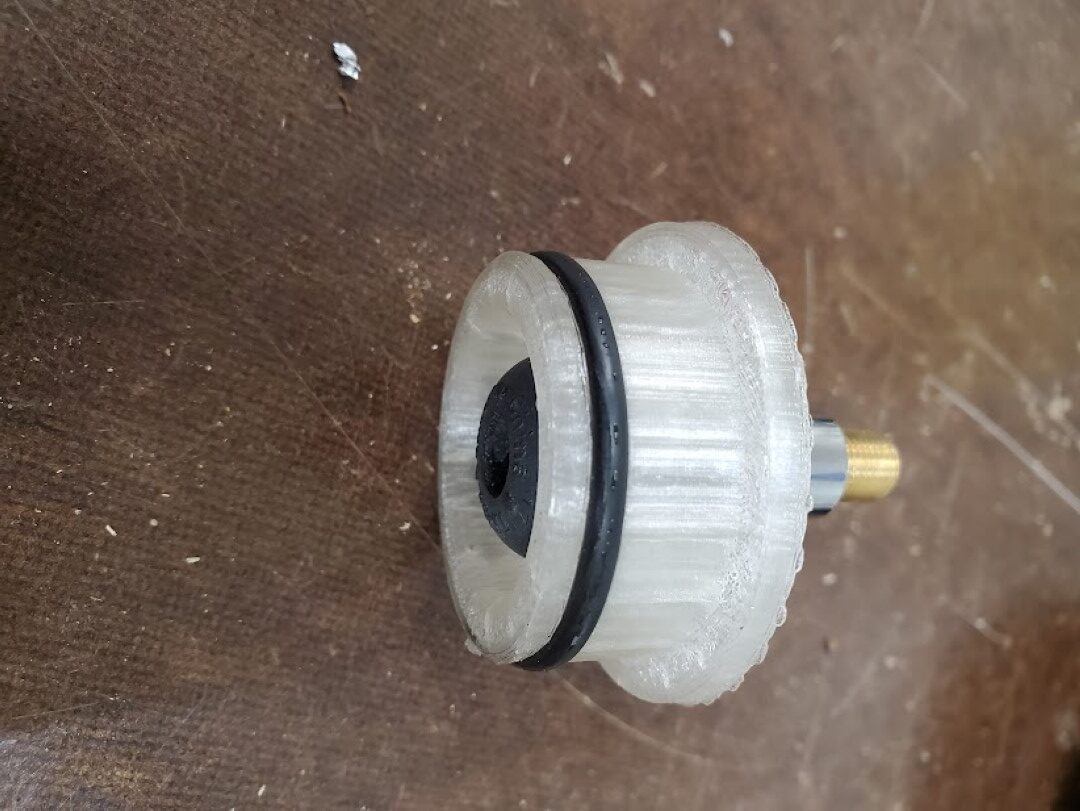
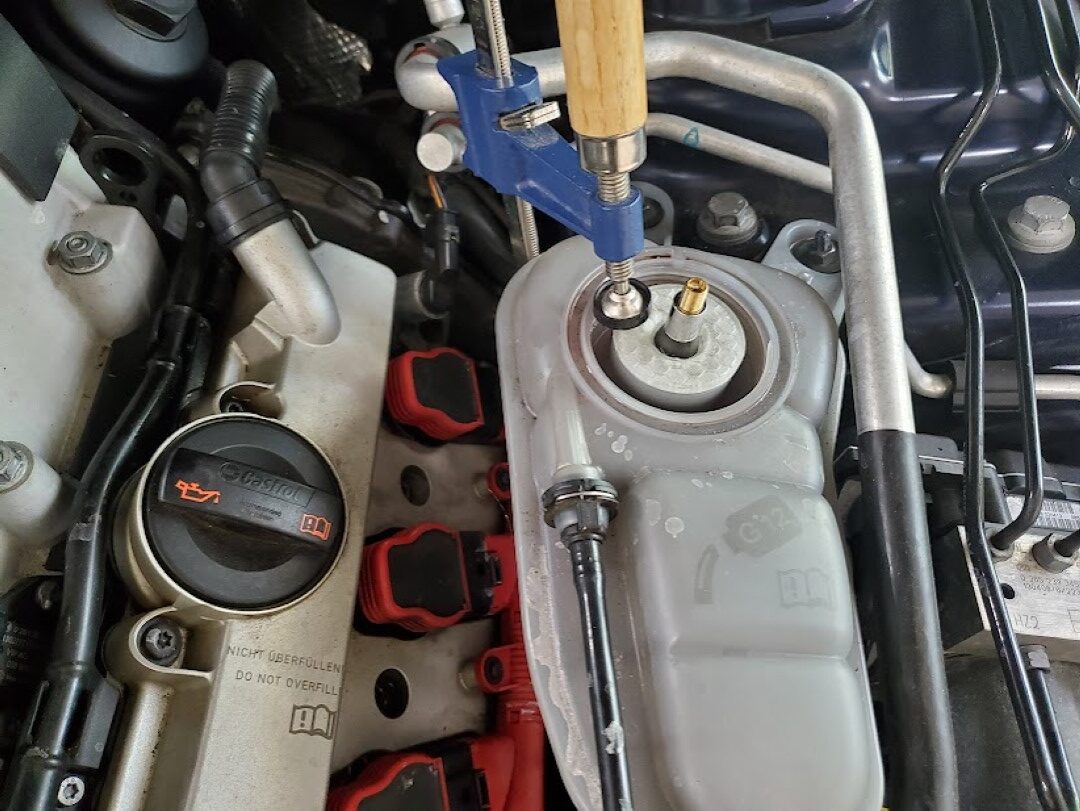
I noticed a small coolant leak on my car recently. It wasn’t clear where it was coming from, only that it was somewhere in the front and only occurred after running for some time. To help troubleshoot this I created a 3d printed adapter that interfaced a tire schrader valve to the coolant tank, sealed with an O-ring. An F clamp held this adapter in place and I pressurized the coolant system to a few PSI. This lead to the discovery of a bad O-ring on one of the coolant crossover pipes at the supercharger, which was easily fixed.
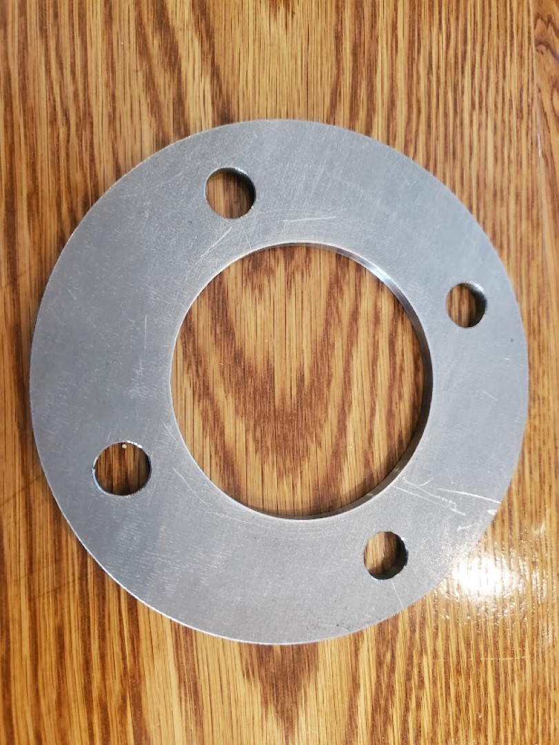
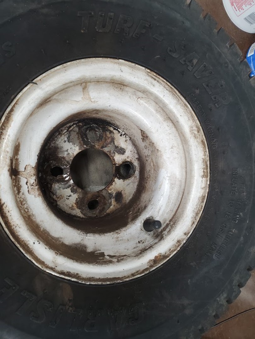
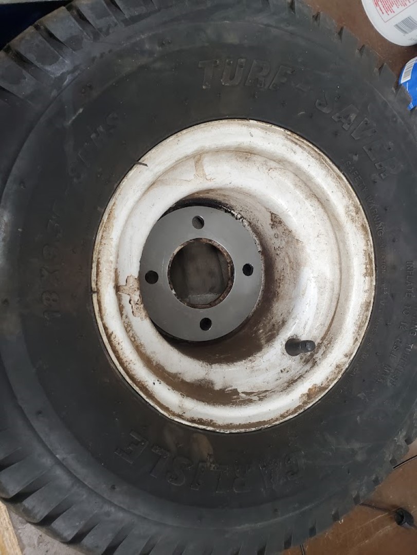
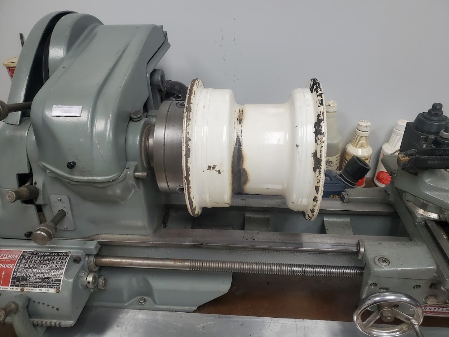
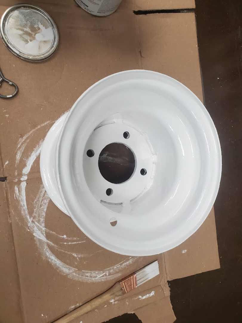
Kubota F2000 Wheel Rebuild
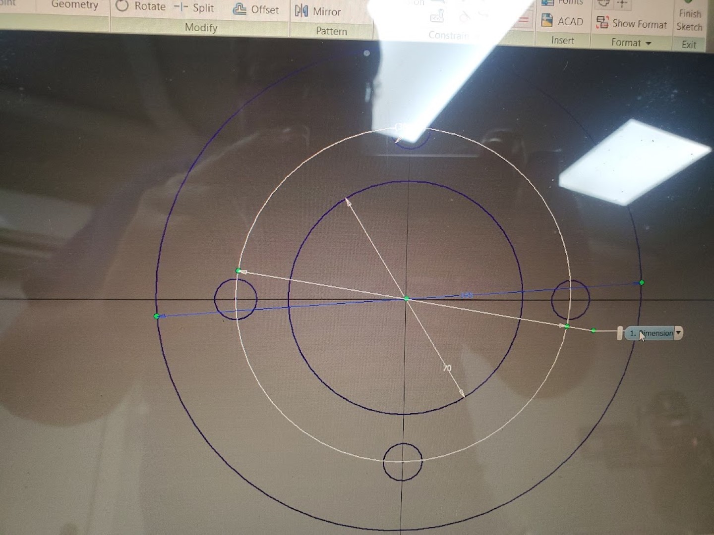
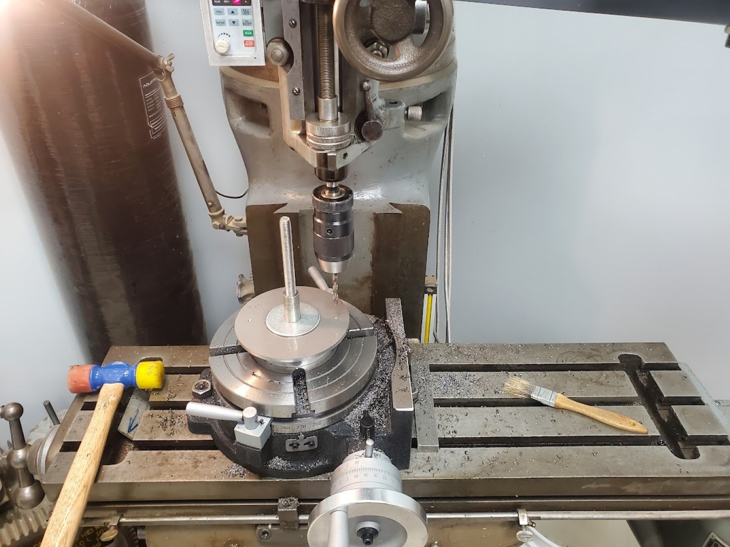
Recently one of the wheels on the mower broke. This hub of this particular wheel has always been a weak point and I’ve welded it back at least once. This time it was too far gone though and I intended to replace it… that is until I realized this wheel is a very odd size and offset that’s specific to this series of mowers. It wasn’t clear that replacements were obtainable. With that being the case I decided to machine a new flange that could be welded in place to reinforce the inner wheel. The flange consisted of a 1/4″ steel plate turned down to the right diameter, then center bored and hole pattern drilled on the rotary table. The flange was then welded in the wheel and the back side faced on the lathe to ensure the face of the wheel would be perpendicular to the axle hub.
Audi S4 3.0T Secondary Air Cleaning
Part 1: Background
A while ago my check engine light began coming on sporadically, after scanning I found this was related to P0491 & P0492 errors. These errors indicate that insufficient airflow is available to the secondary air system that’s responsible for getting the exhaust catalysts up to temperature quickly at start-up. These errors would self-clear, but over time the light stayed on longer until eventually it stayed on.
I first checked all the ‘easy’ stuff related to this fault: the secondary air pump and solenoid both worked OK via VCDS and no leaks were found on any of the tubing. I also tested the “combi” control valves which successfully blocked air flow when blowing through the secondary air pipe and allowed air when manually actuated with a vacuum pump. At this point I ran a good amount of seafoam and intake cleaner through the secondary air pipe that goes under the supercharger, using a HVLP paint blower to push it through the system while the combi valves were held open with vacuum – lots of smoke, no change.
This unfortunately left blockages in the cylinder head’s internal secondary air ‘manifold’ as a most likely cause for the problem, there’s a TSB with lots of good info here: https://static.nhtsa.gov/odi/tsbs/2018/MC-10153120-9999.pdf (Required Reading for this topic!)
Options at this point, in order of consideration, were:
#1 – Take it to the dealer for the 120k mi extended secondary air warranty, I had ~110k mi at that point. I strongly considered this, but in the end it didn’t seem worth the hassle. With it being high mileage by their standards I fully expected to get push-back or some excuse for it not to be covered, while potentially being on the hook for their ‘diagnostics’ fees. Either way this was likely to be a less enjoyable experience than wrenching in the garage over a long weekend.
#2 – Buy the VAS6825 tool and do it myself. The TSB has plenty of info to do the job successfully, OK let’s just order the tool and …….. it costs how much?!?!
#3 – Make the tool myself and do it myself. The tool is simple enough, and I was reasonably confident a usable tool could be made at home. I went with the last option, let’s make the tool….
Part 2: Tool Creation
From photos online, the official tool (fig. 1) appeared to just be two smallish diameter flexible pressure washer tubes: one that’s basically a tiny sewer jetter, spraying forward, and the other that sprays out sideways. The main passage can be cleaned manually (coat hanger, vacuum), so only the sideways spraying tool is needed. The sideways spraying tool also comes with two plates, a bushing, and an attached scale to correctly position jet in front of the perpendicular passages while still allowing some movement for wiggling the jet around for better cleaning. For my purposes the whole bushing, plate, and scale arrangement would also be omitted – I’d be using a camera to locate the distance to the passages and then positioning the tool manually. There’d be no damage risk from a misaligned jet, as water doesn’t cut aluminum at 4000psi, so the water would just come squirting back out around the tool. I assume the official tool only has the extra complexity to justify its exorbitant price and to make it more suitable for use in a professional environment.
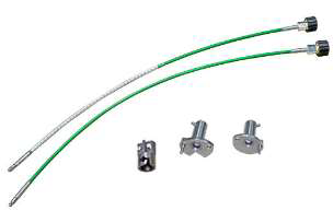
Figure 1: Official VAS6825 tool
With that settled, I only needed a long tube with a right angle nozzle. The small diameter pressure washer hose they use for this isn’t commonly available and even if it were its not clear that any fittings would fit inside the passage. (They use a crimp connection to get around this, but that’d require expensive crimp tooling in the strange tubing size – big money for something that I’d likely never use again). The good news is that the main secondary air passage is perfectly straight, so there’s no reason for flexibility at all. With this in mind the plan quickly coalesced around using some steel tubing. The tubing I selected was a 3ft length of 3/8″OD with 0.083″ wall thickness (McMaster 89955K459). This thickness is massively overkill vs the 4000PSI of my pressure washer, but a big ID isn’t needed for flow and I was more concerned with having enough metal thickness to get good welds.
From there I took a spare chunk of 1/2″ round bar, bored a 3/8″ hole to accept the tubing, and tapped the other side to 1/4″NPT for the pressure washer coupler. (fig. 2) I did this on a lathe, but it could be done with a drill press or drill/vice if centered carefully. This was then welded* to the tube on one side along with a simple plug on the other.(fig. 3) At that point I had a fully sealed tube to which I drilled an ~0.043″ hole on the side of the end, giving me the right angle jet. (fig. 4) The hole size depends on the specs of the pressure washer, check tables online, 0.043″ was right for 4000PSI / 3.5GPM. The official tool appears to have 3 holes – I suppose you could calculate the right hole sizes for this and do it that way, but the single hole is already tiny and any performance loss from this is easily overcome by wiggling the single jet around more/longer. Lastly, add a line along the tool so it’s clear which way the nozzle is pointing. Total cost less than $30.
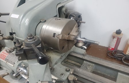
Figure 2: Making the end adapter
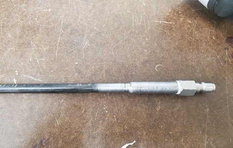
Figure 3: End adapter welded to tube, coupler fitting attached
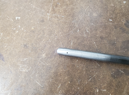
Figure 4:Nozzle Orifice Drilled
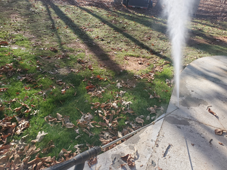
Figure 5 : Testing
*Warning: This is effectively a DIY hydraulic line under a few thousand pounds of pressure. It can
fail forcefully with risk of injury.
Part 3: Cleaning
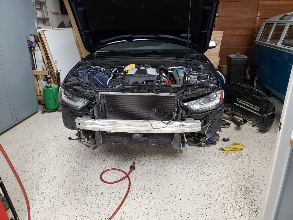
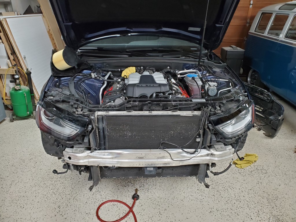
As always, remove the entire front of the car using whatever method/sequence you prefer. You’ll need unobstructed access to the front of the engine. I was able to suspend the bumper/radiator support from the ceiling and hinge it open like a gate to avoid disconnecting the AC lines. Note though that this puts strain on the upper radiator hose and that will crack the coolant crossover pipe, so disconnect it first. I only left the hose connected because I couldn’t get it off the pipe without destroying it, so it was probably doomed either way.
Get access to the secondary air ‘manifold’ freeze plugs (fig. 6); there are a number of things in the way (belts, coolant flange, hoses, etc) but if you’ve gotten this far you’ll figure it out. Pop one side of the freeze plug with a drift punch and it’ll rotate so you can yank it out with needle nose pliers. Remove coils and plugs at this point also.
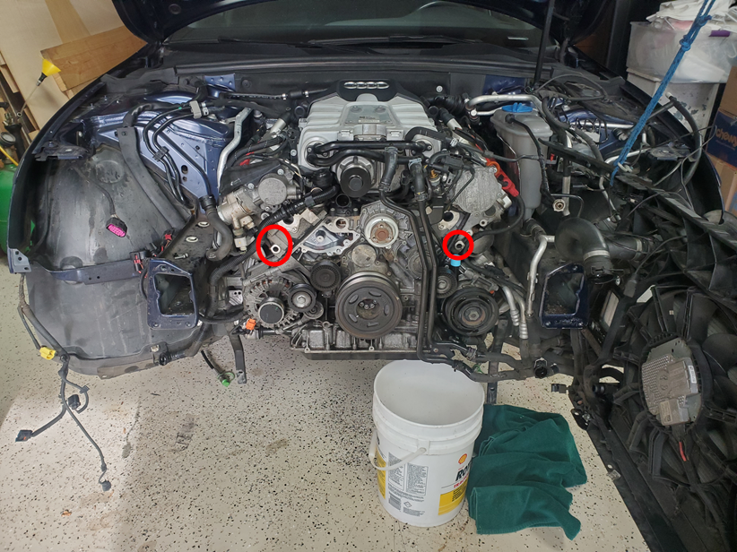
Figure 6: Secondary Air Passages from the front of engine
Next use the right angle camera mirror to find the air passages with the angle of the exhaust manifold flange for reference. The passages are drilled straight from the flange (where they dead-end) up to the back of the exhaust valves. Point the mirror up in that direction, it’s the part of the passage that goes up into the valve that we want to clear, the other part that dead ends onto the back of the exhaust flange is only there because it’s much easier for them to manufacture the head that way. Once the passage is centered in the field of view mark the camera cord where it enters the cylinder head, I used colored electrical tape with different colors for each bank; repeat for all 6 passages. (fig. 7) Reference measurements in table 1.
| Driver (US) | Passenger | |
| Front | 75mm | 45mm |
| Middle | 165mm | 135mm |
| Rear | 255mm | 225mm |
Table 1: Distance from Port Edge to Passage Center
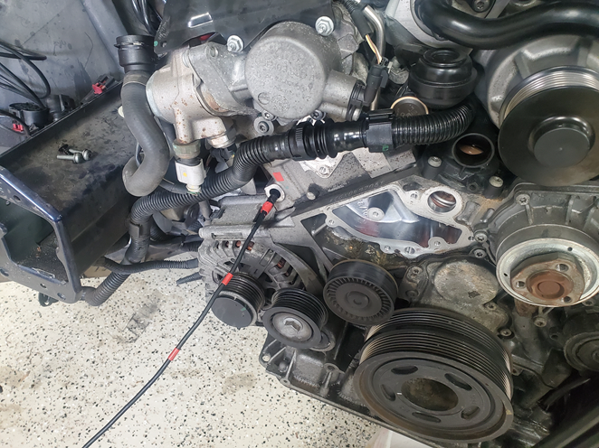
Figure 7: Marking the individual passage locations
Warning: Make sure the camera body is securely attached to the cord! Even though my camera (depstech) appeared to be one piece it decided to separate – the cord pulled out and left the camera guts and front body in the passage. This could be disastrous as you’d then need to drop the transmission to pull off the combi valve to push the camera body out from the other side. I was extremely lucky this happened close enough to the end that I was able to access it with small needle nose pliers and pull it out. It re-assembled no problem, the cord had a connector inside the camera body. After that I epoxied the cord to the camera body and wrapped them together with electrical tape for extra insurance.
Next put the camera and cleaning tool next to each other with the mirror and nozzle orifice aligned and transfer all the markings onto the cleaning tool.(fig. 8) All that’s left at this point is to drop the exhaust before the catalysts, setup a big storage container to catch the water, insert the tool, and start blasting. (fig. 9) You’ll also want a catch container up front under the tool, drape a wet rag (if it’s dry it’ll blow away) over the tool so that the water coming out will hit it and drop into the catch container. Insert the tool to the depth of the first marking and rotate so the line on the tool is facing the right way (the same angle you found the passage with the mirror). Set a timer for 3min and pull the trigger. You’ll get an initial blast of dirty water from the main passage as the jet eats through the blockage, this should pass almost instantly. If it doesn’t, you’re off-target – try rotating and moving the tool in/out until water stops blasting out of the front. It’s very apparent when you’re on-target, no water comes out of the front and there’s a satisfying gurgling noise. For the remainder of the time I just moved the tool in/out and rotated back/forth, changing direction when water began coming from the front. Repeat for all passages.
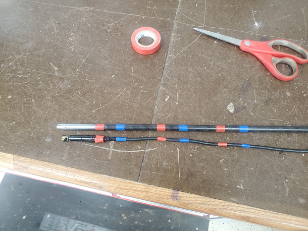
Figure 8: Transferring passage depths to cleaning tool
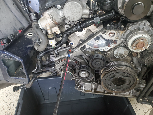
Figure 9: Blasting! (not shown aligned)
Once complete, use a vacuum extractor to try to pull water from all the plug holes. It was clear during blasting that one exhaust valve was open on each bank, and these two cylinders did have a little bit of water. Next crank it a few times with the plugs out as a precaution before fully reassembling and clearing all the codes.
The camera had a hard time focusing on the clogged ports, I had to really work to get usable pictures but you can see a very small dark area in the middle of the before shots – I believe these were the only open area and you can definitely see the edge of the port, so everything in-between was crud. (fig. 10) After cleaning I got great pictures with no effort at all that immediately showed fully clear. (fig. 11) The process was a success and the code has not returned as of many months later.
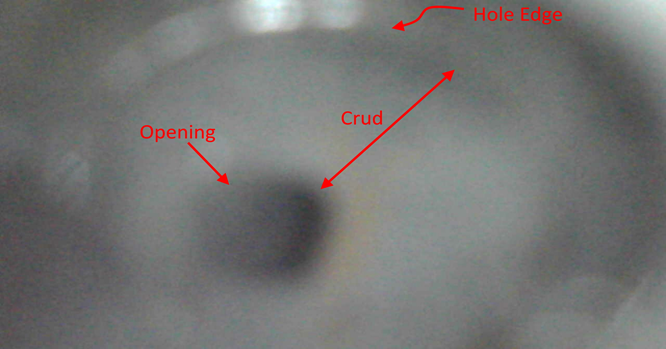
Figure 10: Typical Passage Before Cleaning
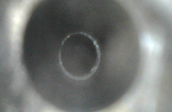
Figure 11: Typical Passage After Cleaning
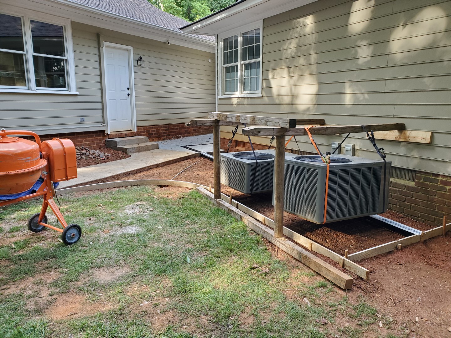
Sidewalk Project: Nearly Complete
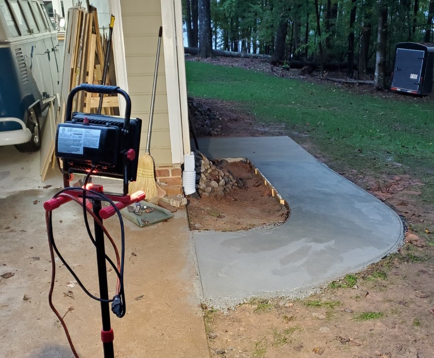
The next two phases of the garage sidewalk project have been completed. The first of these was relatively easy, just a flat section in an alcove between the house and garage. A channel drain was added at the roof drip line and conduit added for future utilities to access the area (hopefully fiber eventually). The second phase was not as simple since there were heat pump units in the way. To get around this I installed a ledger board to the wall framing then made a frame out of old landscape timbers, with the frame legs outside the concrete area. The units were then carefully lifted onto the frames with ratchet straps, making sure not to stress any of the electrical/refrigerant connections. Concrete was then poured the same as before.
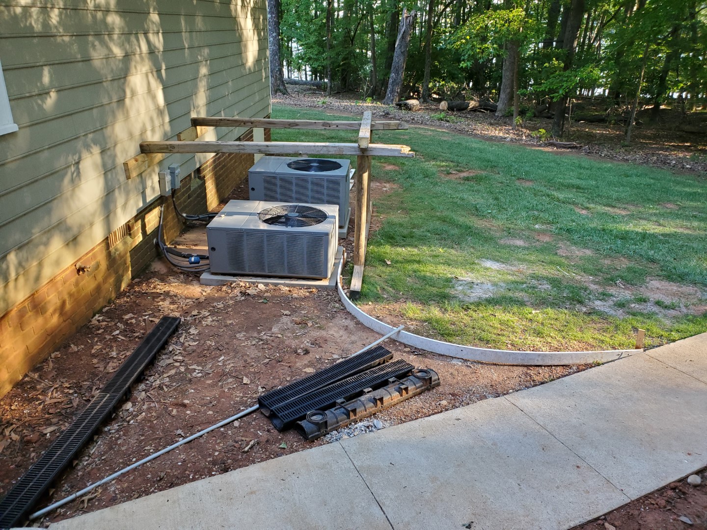
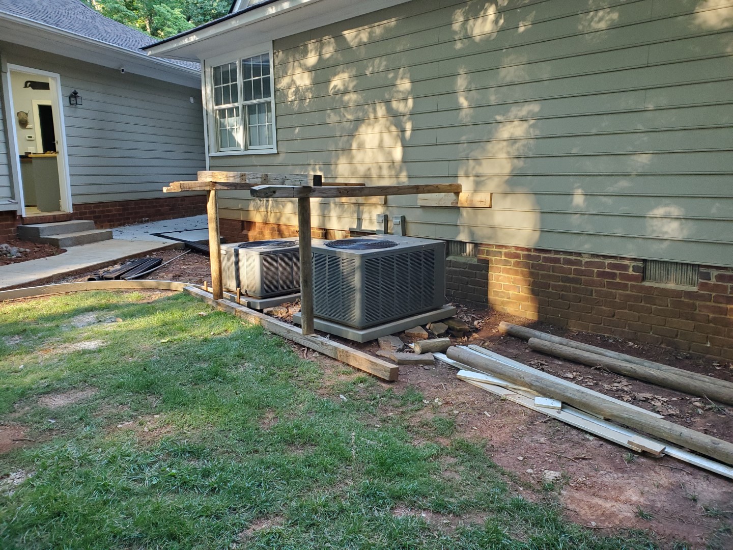
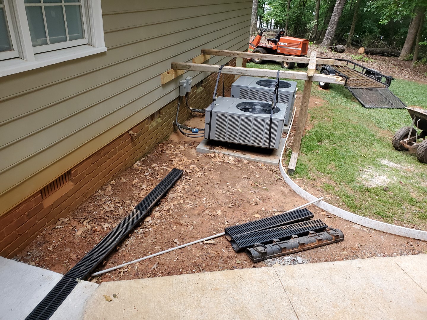
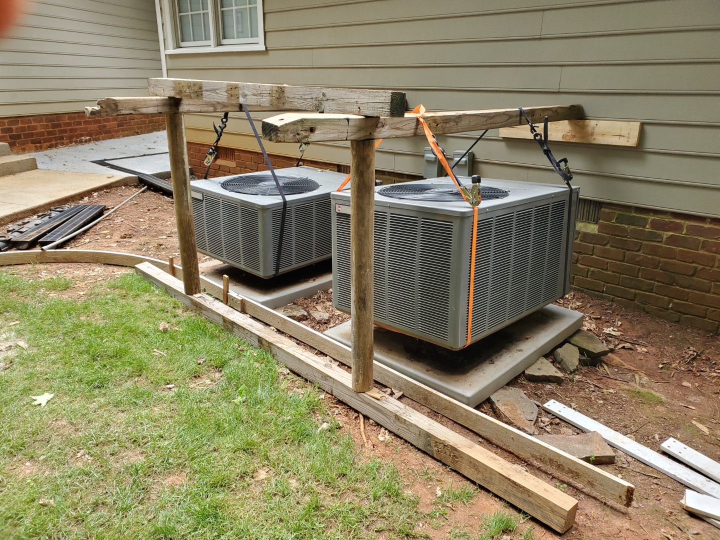
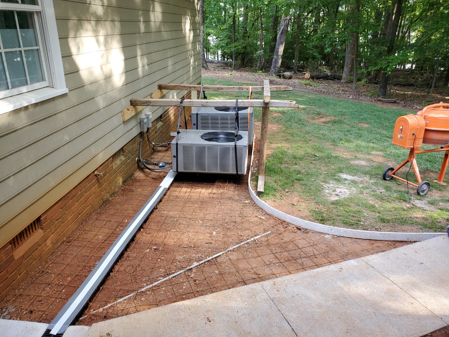
Next phase is one more small section from the heat pumps to the end of the wall, this will catch the rest of the rain run-off and direct all of it into a pipe that will run under the grass.
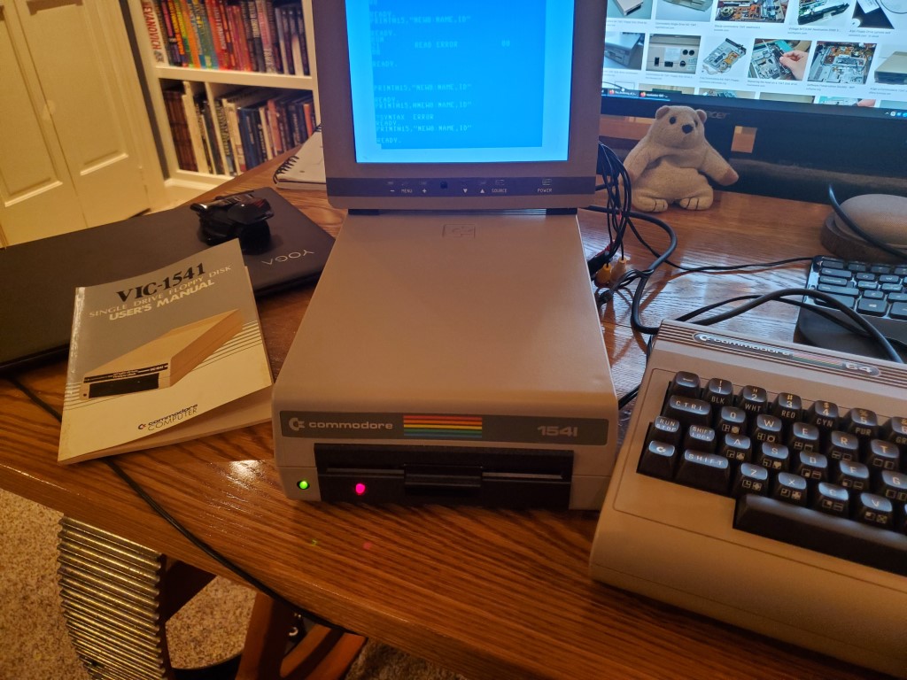
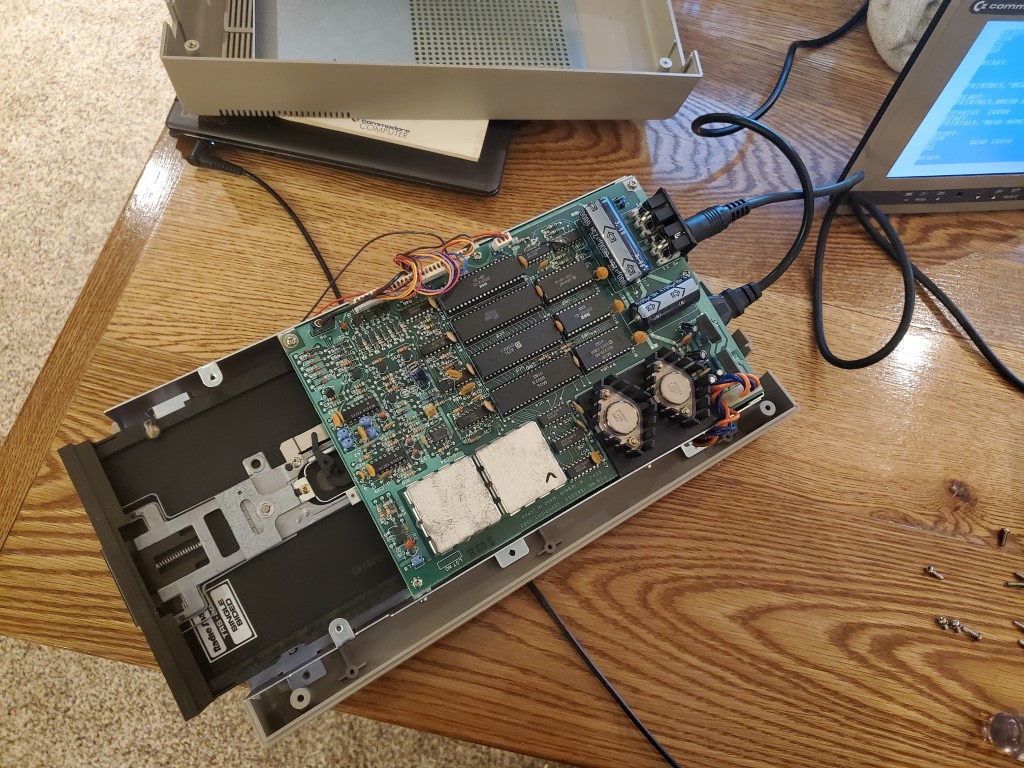
Commodore 1541 Disk Drive Repair(?)
I spent a long time this weekend troubleshooting a Commodore VIC1541 disk drive only to have it spontaneously start working. I cleaned the belt, de-oxidized the connectors, re-flowed some suspicious looking solder joints, and tried a variety of different disks. Its working reliably now though and I’m able to use it as a bridge between the internet and the C64 via a ZoomFloppy. The ZoomFloppy connects the 1541 to a PC via USB so that disk images can be written and then later loaded on the C64.
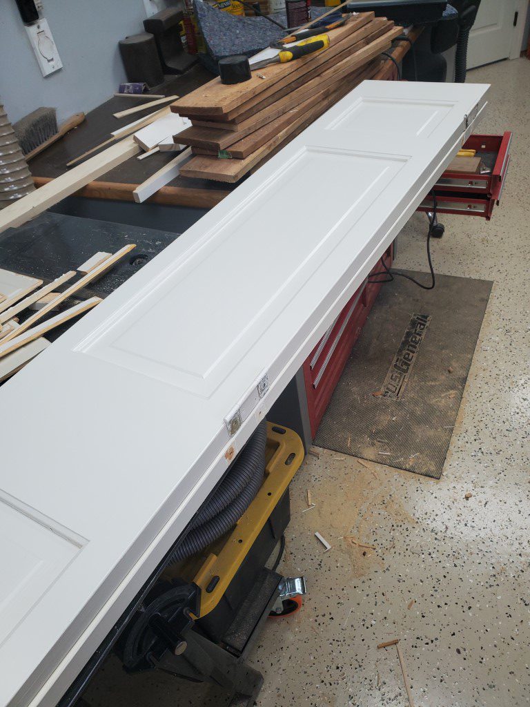
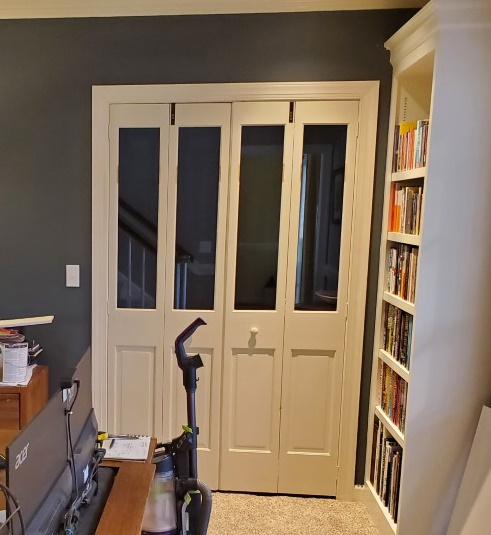
Glass Bi-fold Doors
The home office has some bifold doors connecting it to the foyer. Normally I’d like to leave these doors open since it allows light & visibility to the front door, but that would also allow cats to enter the office (usually at the worst times). The solution seemed to be changing to bifold doors with glass panels, however these are very expensive. Since the existing doors were already good quality solid wood though, a good compromise seemed to be modifying them to add glass. I was able to find tempered glass for a reasonable cost online, so I went ahead with this project. Tempered glass is the key since it will break into small (less dangerous) pieces, it’s a code requirement for doors in most locations. The process went as follows:
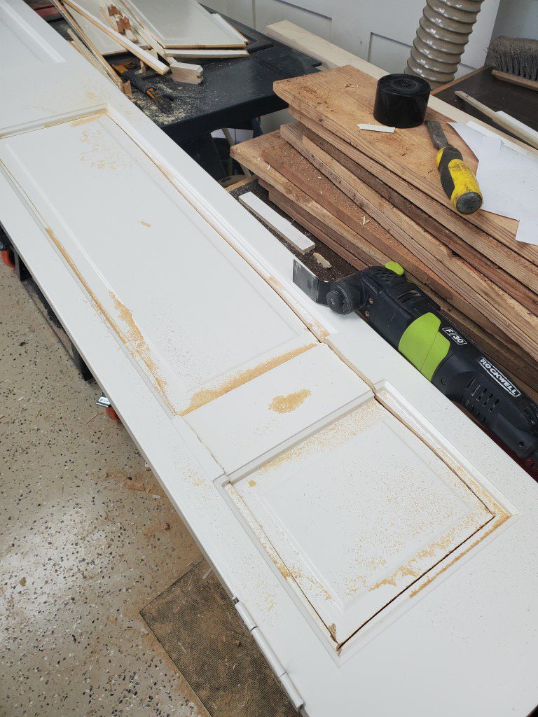
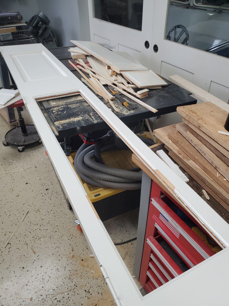
- Cut a middle section out of the panels on each door. This allowed room for the next step.
- Pull the remnants of the panel edges out of the groove in each door frame.
- Route one side of the door frame flush with the bottom of the groove.
- Install glass panel.
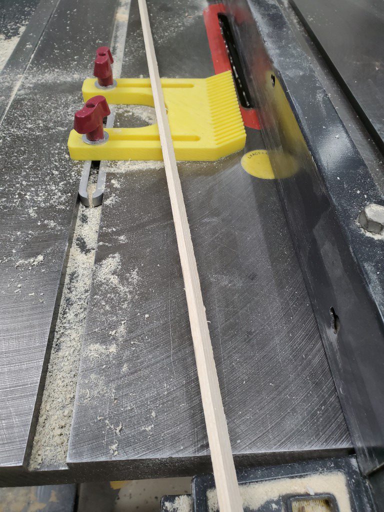
- Make trim piece to hold glass in place, this piece basically replaces the piece of the original groove edge that was routed away.
- Carefully tack trim in place.
- Fill/Sand/prime/paint trim pieces.

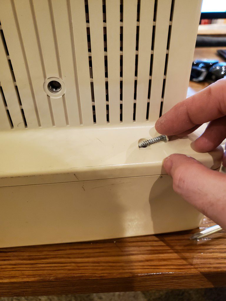
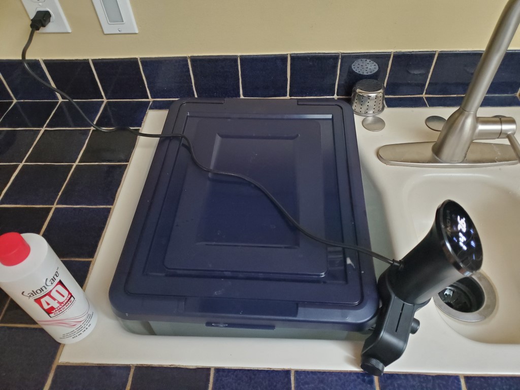
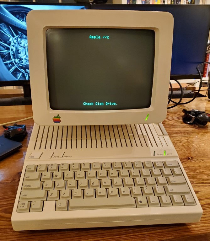
Apple IIc Monitor Refresh
Following-up on the Apple IIc computer refresh, I recently cleaned up the IIc’s monitor. Disassembly of CRTs can be dangerous due to high voltages, but at the point of disassembly it had been unplugged for a few weeks and I made sure to discharge the tube and capacitors as soon as I could. From there it was just a matter of cleaning the plastics, using a magic eraser for scuffs, and de-yellowing. The de-yellowing is accomplished by covering the surfaces in peroxide, putting the parts in bags, and then submerging those bags in a bath of hot water kept warm by a sous vide heater.
A few of the potentiometers for size/position/brightness were dirty, causing the picture to cut out unless adjusted perfectly. This was resolved by spraying some contact cleaner under the knobs and exercising them.
Sidewalk Sequel
The next phase of the garage sidewalk project has been completed. Same process here, but a larger section was made possible by the addition of a concrete mixer. At the same time the old railroad timber steps to the back door were replaced with concrete. Next phase will be filling in an alcove between the garage & house (along with adding a channel drain to finally catch water from that area) and then last a section under the heat pump units.
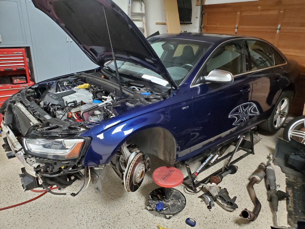
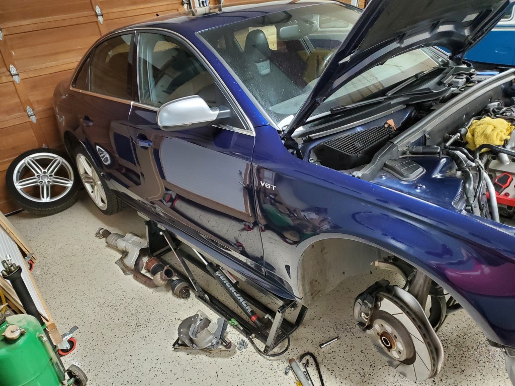
S4 Clutch Replacement
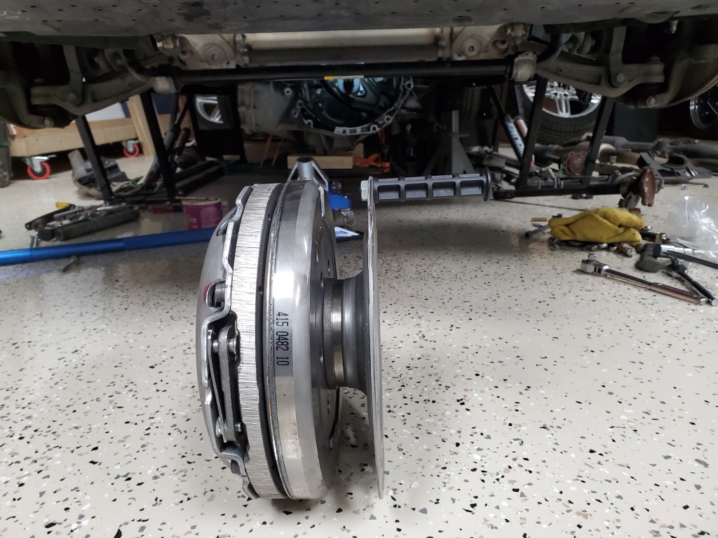
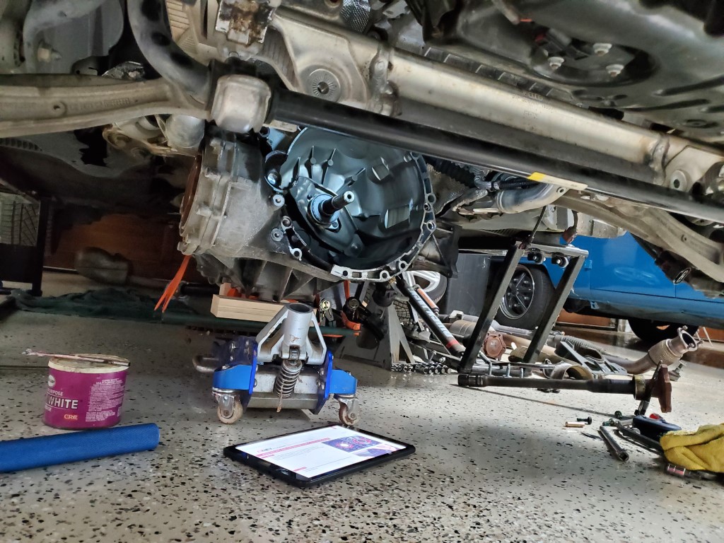
The clutch on my car finally started slipping when under full power. This wasn’t completely unexpected since it originally came from a high-traffic area of NJ. I was able to get it replaced over the past two weekends plus a couple of weeknights. There wasn’t anything particularly difficult about this and it’s well documented online, just lots of small challenges in a row with figuring out how to access various fasteners.
While I was at it I took the opportunity to replace belts, plugs, change the supercharger oil, etc.
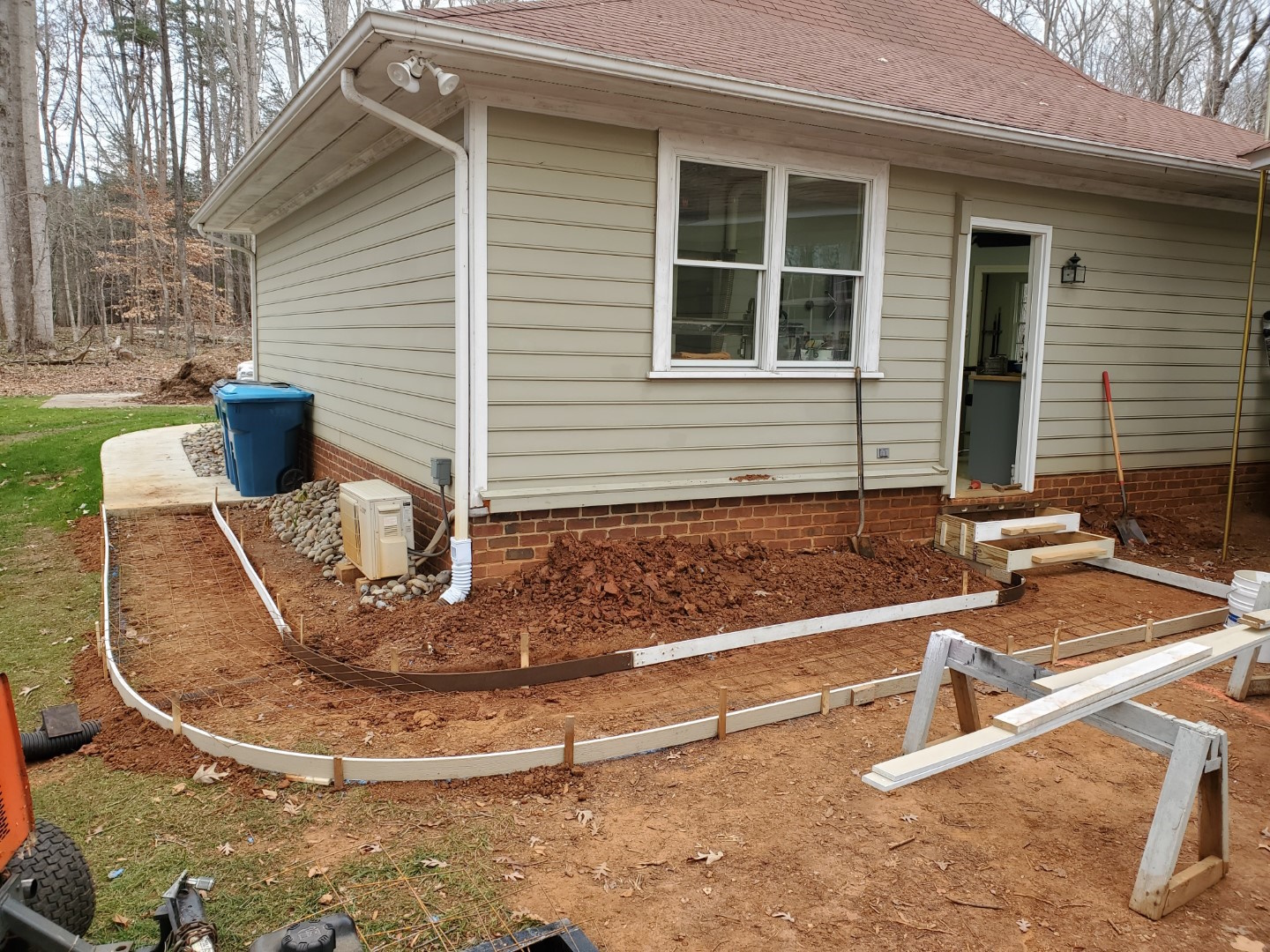
Trash Can Sidewalk
Quick project this weekend to create an area for trash/recycling can storage. I used some odd 1×4 composite trim type boards left by the previous owner for most of the forms, for the tighter inside bend I cut a few strips of 1/8″ masonite panel and glued them together in-place. I also setup a length of drainage pipe to direct the gutter downspout under the sidewalk. Wire grid was set in place, then concrete hand-mixed in a wheelbarrow and poured. A few hours later I finished with a broom finish.
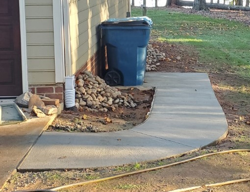
Eventually I may add a small fence/wall, but just getting the cans out of the driveway is a big improvement on its own. This yard in this area was holding a pile of landscaping rock until recently, now that it’s been moved the area will be planted with grass.
The sidewalk will eventually be extended around the garage, I’ll likely get a small cement mixer to make the process go faster – mixing a pour this size by hand it becomes difficult to mix and place the concrete fast enough that the beginning isn’t curing differently than the end, which makes finishing tricky.