

The Piano controller will be based around a Raspberry Pi Zero W. I had originally considered using a spare Arduino, however since the project will require a lot of file handling and a web server, having a full general purpose OS is much easier than shoe-horning it all into the Arduino. The Raspberry Pi also has a wifi adapter built-in, simplifying wiring.
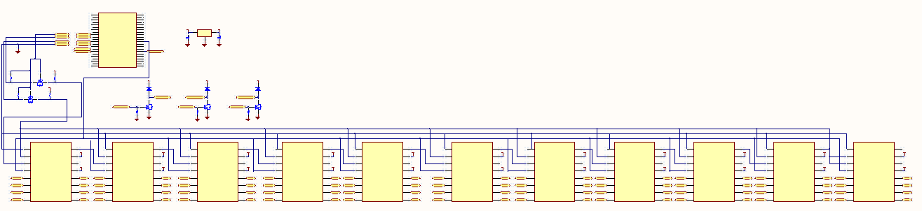
Unfortunately the Raspberry Pi doesn’t have the ~90 outputs that are needed to control the piano’s valves. This is a common problem in electronics and micro controllers – it’s assumed that the designer/integrator is going to provide their own output channels that are most suitable for their device. Instead, the Pi has several low voltage/current outputs that can be switched extremely quickly. I’ll connect these outputs to shift registers, clock all 88 valve bits into the shift register’s ‘memory’, and then send a signal to latch these new values to the outputs. This will be repeated quickly enough (~1000 times each second) that for my purposes the ‘remote’ outputs at the shift registers will appear to instantly follow the valve output commands from software.
74HC595 is an extremely common 8-bit shift register that many examples are based on, unfortunately it’s limited to 35mA outputs at 5V. This could still have worked, but would have required adding a transistor switching circuit to each output to achieve the 200mA @ 12V that the valves require. Going that route would have meant half of the design or more would have been dedicated to individual transistors/resistors, leaving a lot of room for errors during the build. To avoid this I found the MIC5891; this is essentially the same device as the 74HC595 but with built-in output drivers that can provide up to 500mA at up to 50V for each channel. The MIC5891 also has built-in protection for switching the valve’s inductive load, so this selection also avoided the need to add external protection diodes. The only minor problem created by the MIC5891 is that its inputs are all 5V and the Pi outputs 3.3V; this is resolved by a simple FET level shifter.
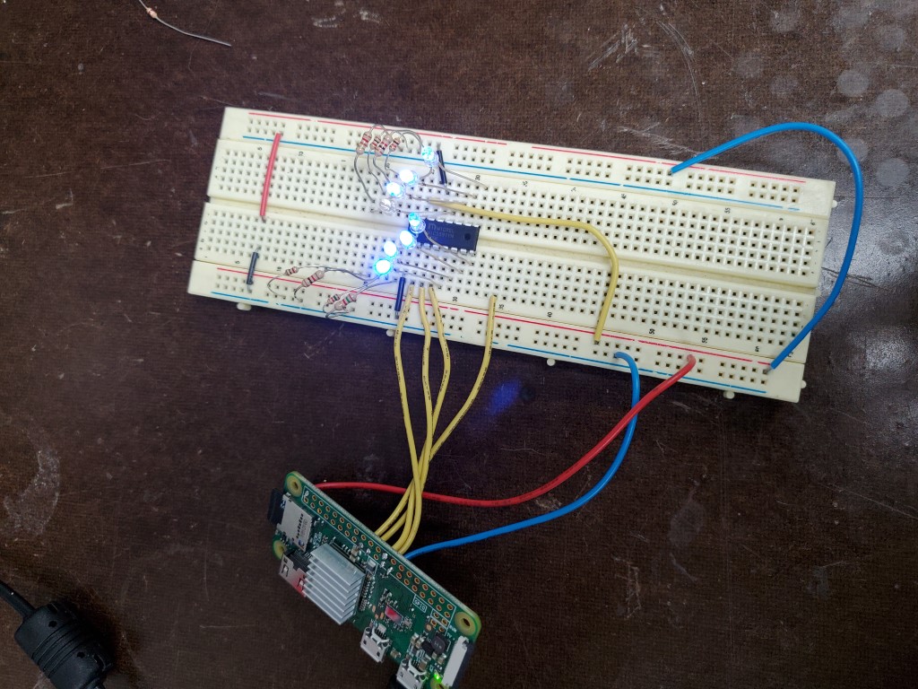
Once the MIC5891’s arrived I did a quick breadboard test with the PI powering a single shift register with some LEDs. In this test the MIC actually accepted the PI’s 3.3V signals, but I wouldn’t trust this to be reliable and will still include the level shifter on the full board.
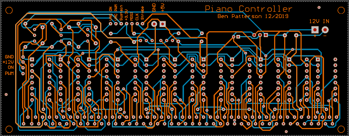
To finish the design I added a few FET switches which will allow me to eventually route spare outputs on the Pi through this board to a satellite board that will control the vacuum pump (On/Off/Speed). I also added a 12V to 5V DC-DC power supply so that I can bring a single 12V supply into the control board and have it power everything, including 5V back out to the Pi. This was all drawn up in CircuitMaker.
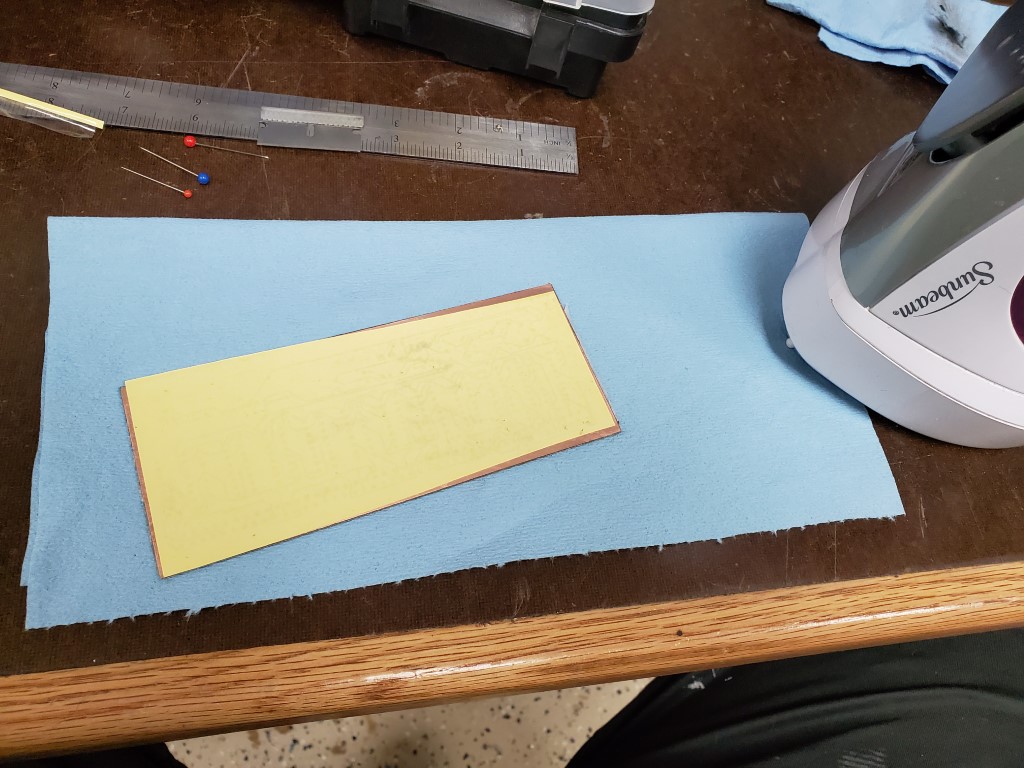
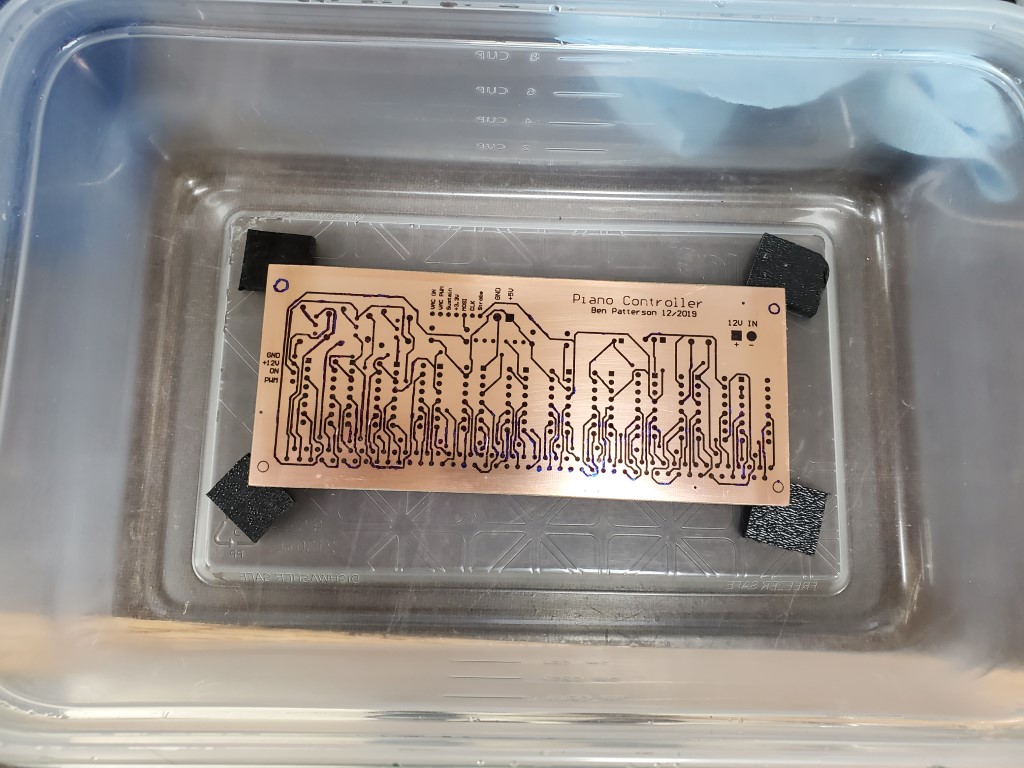
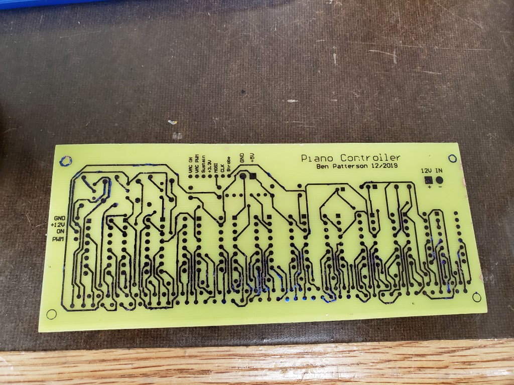
Creating the actual board consisted of printing the circuit design onto toner transfer paper, with scaling 1:1 and with the top layer mirror-imaged. I cut the board blank to size and drilled small holes that I had added to the design as alignment points. The board was then cleaned carefully with fine steel wool and denatured alcohol and then I ironed the transfer paper onto the board. When the board had mostly cooled I pulled off the transfer paper revealing the design. In the past I had used photo paper for transferring toner; this was my first time using purpose-made toner transfer paper and it definitely was much better – the board only required minor touch-up with a fine tip marker prior to etching. After etching in Ferric Chloride, steel wool and denatured alcohol were used to clean the toner/marker from the board.
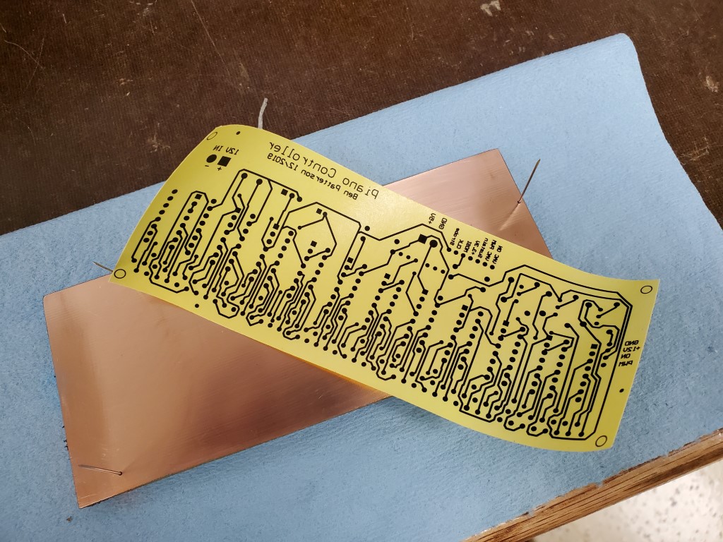

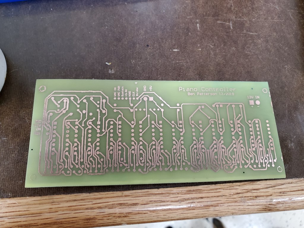
The next steps are to drill all the pin holes and to fully tin the board to increase the ampacity of the traces and prevent corrosion, I’ll do this prior to populating and testing the board.
