Balalaika Repair
It had been in storage and a few parts were missing that needed to be replaced:
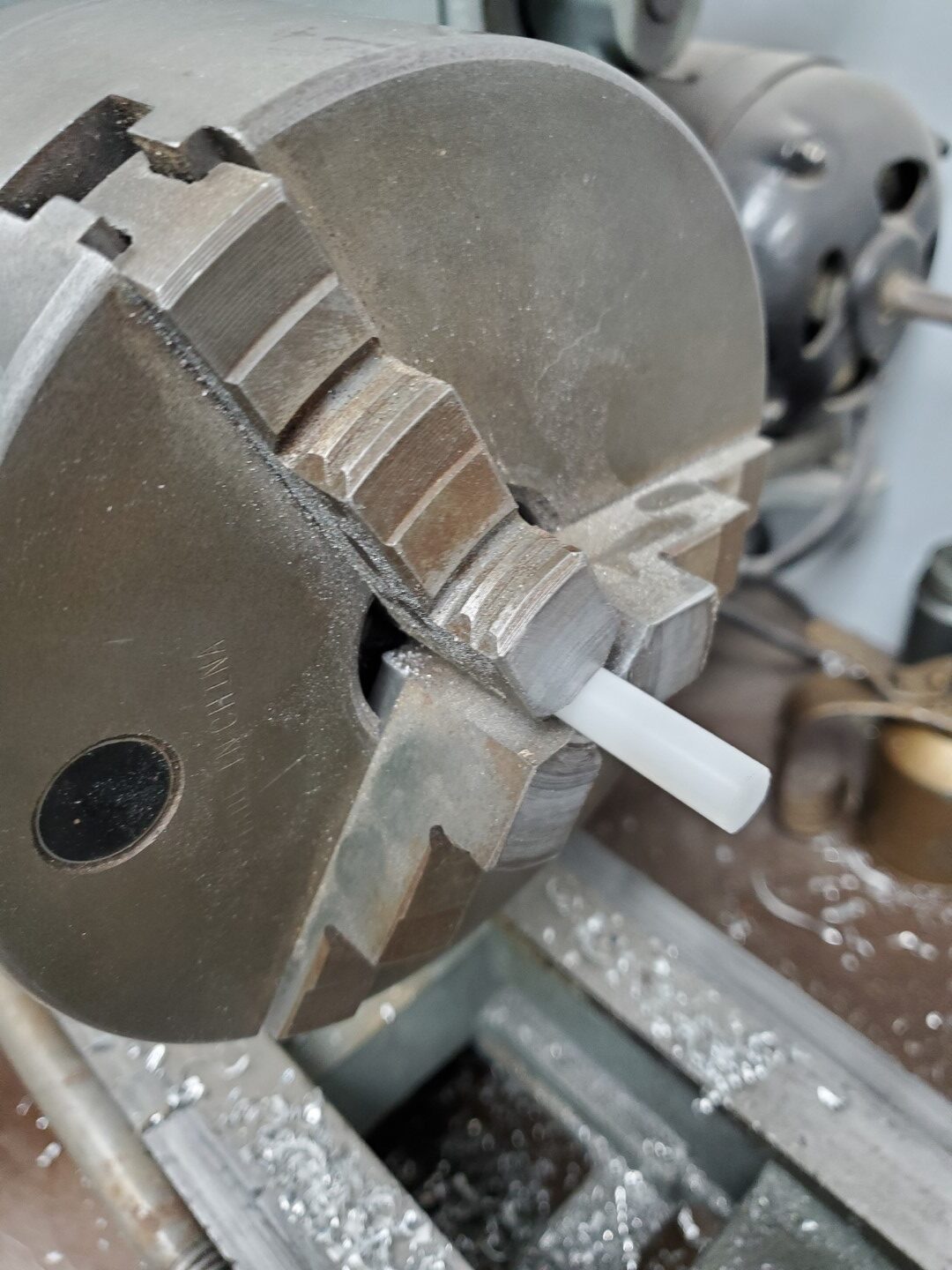
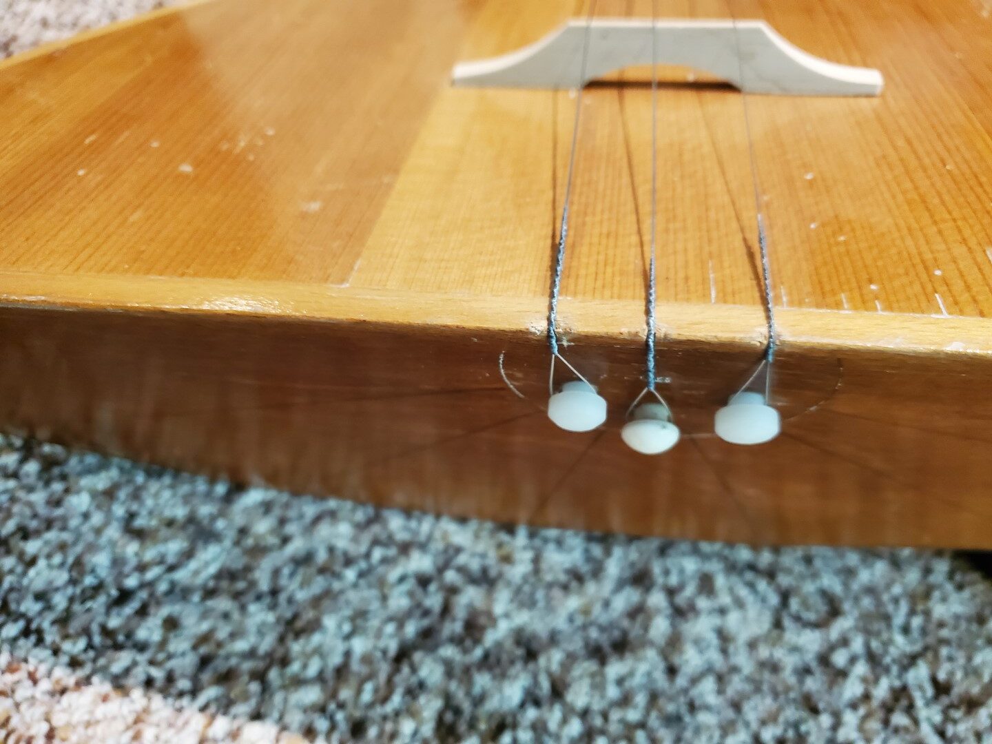
– End Pins – 1 of the 3 end pins remained and I used it as a reference for turning 2 more matching pins on the lathe from a plastic rod.


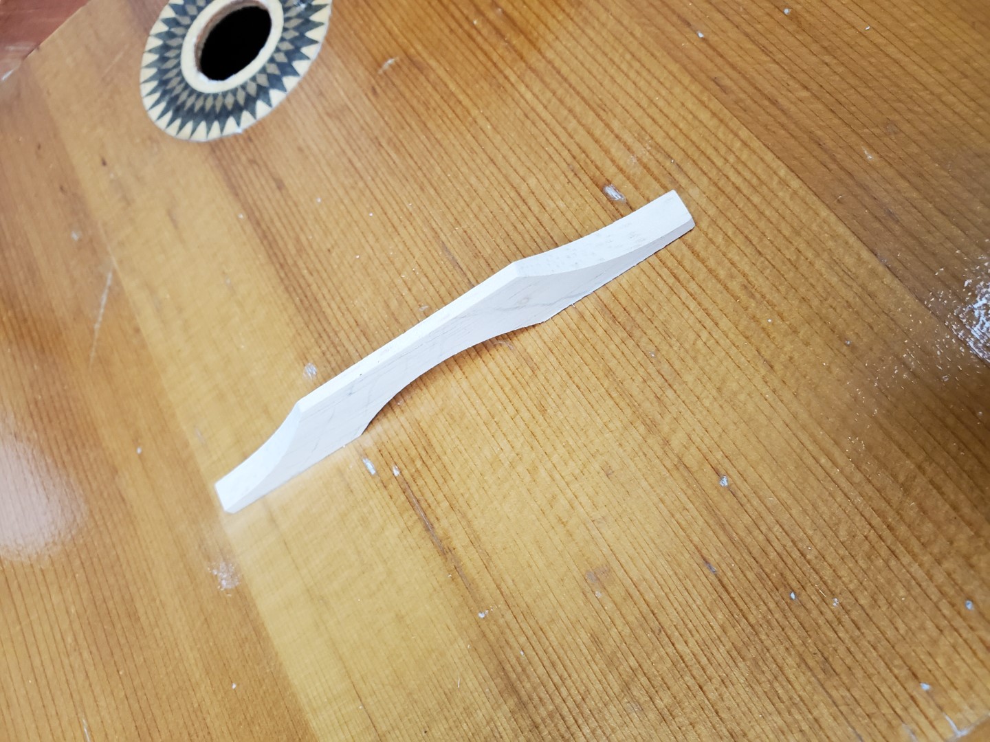
– Bridge – The bridge was missing but I found dimensions that seemed to match the shadow that had been left by the original bridge; I used these dimensions and some reference photos online to make a replacement out of a scrap of maple. This was very quick work with the belt sander.
– Strings – This was the easiest part, available online.
With the parts replaced we were able to tune it and it seems to play OK…


With an endoscope camera I was able to find two labels inside:

Left Translation: Balalaika. Article #205. Airbrush method finish. Nationwide Standard of Russian Soviet Federative Socialist Republic 83-72. Price 6 rubles 70 kopeks. Leningrad, 15 Chapaev St.
Right Translation: Ministry of Local Industry of Russian Soviet Federative Socialist Republic
Main Directorate of Production of Musical Instruments
Lunacharsky Factory of Folk (plucked string) musical instruments
Leningrad
The left label is also stamped with a 1973 date
Saw Milling v2.0
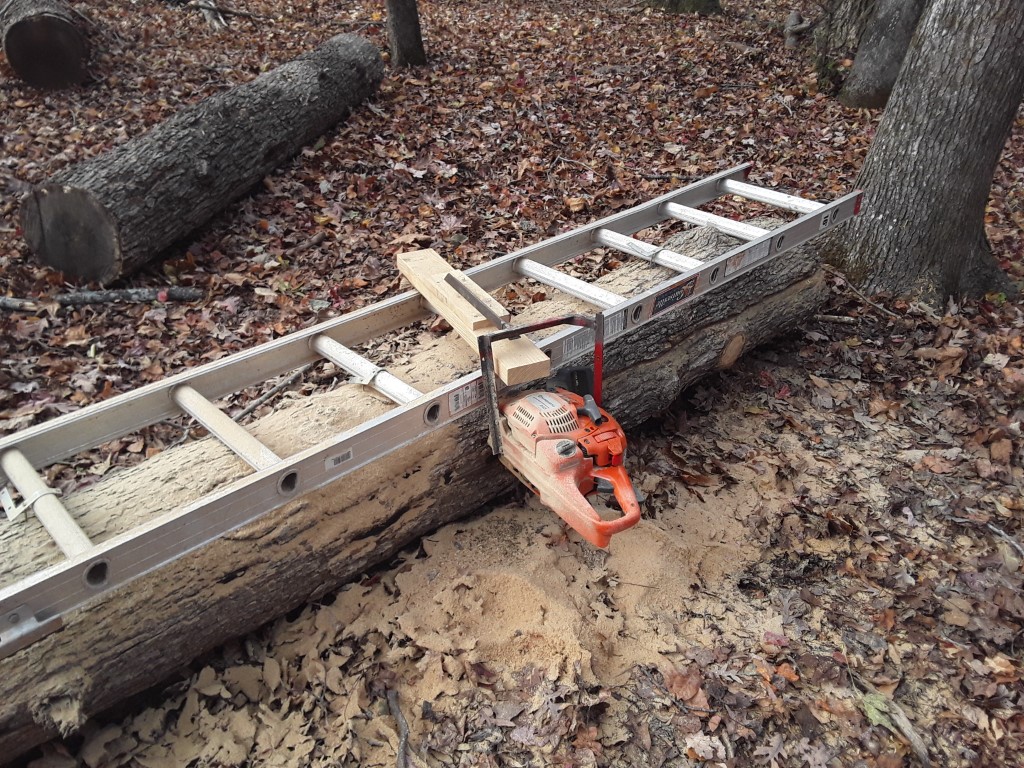
A while back, in anticipation of more log milling, I made a jig for holding the chainsaw level along the length of the cut. This is basically a homemade version of an ‘Alaskan Sawmill’, with a few changes. Since I processed last winter’s log recently it made room for another in the drying area, so I finally had a chance to test out the jig this weekend. For the first cut a ladder is secured to the top of the log to establish a reference surface.
I opted on not tie the reference block into the end of the bar, since I have a limited bar length. Because of this, I also couldn’t make the reference block adjustable without introducing too much flex. Instead, I set it at the maximum board width I may need, and for all thinner boards I’ll add more wood to the block or log to shim it. This also gives me the ability to cut from both sides for a log that’s up to ~2x the bar length.
Altogether this test seemed to work great, the cut was extremely flat compared to the previous log that was cut free-hand. It was fairly slow-going though since I was using a standard chain; I have a ripping chain on order that should cut faster with the grain, I’ll install it before finishing this log.


First Finished Lumber from Saw Milling
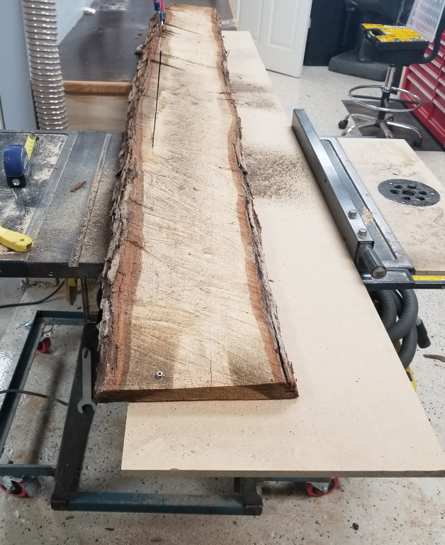
The oak I cut down last fall and “milled” last winter (this post) seemed to be dry enough to attempt further processing. Since the milling was very crude, there was a lot of thickness variation and therefor a lot of variation in moisture content. It hasn’t been a full year, but it’s also been a hot/dry summer. I measured an average of about 11% moisture content, which is near the lower limit that can be expected for outdoor drying in my area. Turning the log into lumber consisted of a few steps:
#1 – Rip a straight edge along one side of each plank. Since the log doesn’t have any straight reference surface, I created a sled out of some spare 1/2″ MDF and attached the plank to the sled. The sled provided a straight edge to ride along the table saw fence, ensuring a straight cut edge on the plank.
#2 – After the 1st straight edge is cut, the sled is removed and the newly cut straight edge rides against the fence while the other side of the plank is ripped.
#3 – With the sides now flat and parallel, a flat face needed to be established. To do this I put the plank on a long 2×6 and shimmed it until it no longer rocked. I fed the entire stack through the planer with multiple passes until a flat face was established across the entire side.
#4 – With 1 flat face established, the plank was removed from the 2×6 and fed through the planer until a new face was established across the other side.
#5 – The ends were cut on the table saw to be square with the sides.

For this initial test I used the board from the top of the stack. This top board had warped a good bit, so instead of trying to plane the warp out, which would have created a very long/thin board, I cut the plank into sections to create shorter/thicker boards. For future drying stacks I need to add weight on the top to prevent warping of the top planks(s).
After planing the first board I am seeing some cracks form. The normal process is to allow the wood to finish drying inside after the outside drying phase is complete, so this wasn’t necessarily a surprise. I’ll likely leave the rest of the log in the garage to finish drying to ~8%, and then re-process the test pieces with the full log once they’re fully dry and stable.
I’m planning to ‘mill’ the rest of the logs soon and put them in this log’s prior location outside, protected by the eave of the garage roof. These should be ready for initial processing and moving into the garage next fall; by then this initial log should be processed into final lumber and will be out of the way.
Exterior Projects & ‘Custom’ Molding
This weekend I finally got around to a few exterior projects at the house:
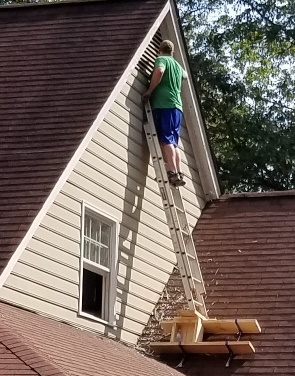
– One of the gable sides had flaking trim paint on its vent / rake boards and needed fresh paint on the siding. I sanded and repainted the trim and then put several coats of new paint on the siding. This gable end is the only original Masonite siding on the house that’s exposed (the entire back was replaced with LP Smartside by the previous owner, the dormer siding I’ll be replacing soon, and the rest of it is either under the porch or deep eaves where it never gets wet). Anywhere Masonite siding can get wet it’s critically important to keep good paint on it to avoid swelling; I think I caught this just in time. Getting access to the area took a little creativity and involved a few roof brackets, planks, and making a platform/box from 2×10’s; it was very rigid once all the parts were secured together though.
– Installed gutter guards. Leaves should start falling soon and I’ll see how it goes, anything will be an improvement.
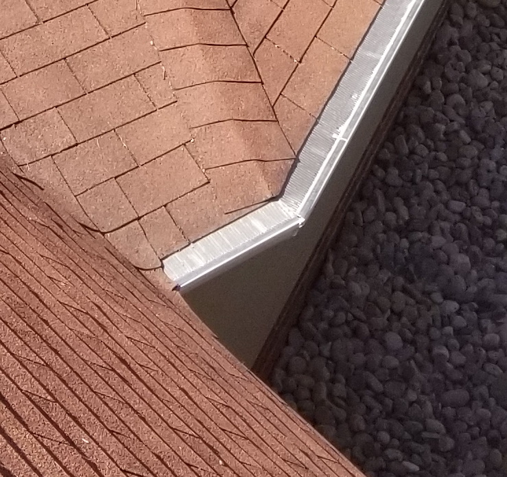
– The gable side on the back of the house had a rotted rake board and molding. Replacing the rake board was no problem; I just needed to rip a 1×6 to the exact width and put a slight roundover on the bottom edges to match the existing rake boards.
(I didn’t get a before shot, but this shows the new board and missing molding. The dark area of the old board was covered by bad molding, but is still good. It will get primed before installing the molding, and this way the seams are staggered for stability)

Unfortunately the molding that’s between the rake board and shingles (conveniently called ‘shingle molding’) is not readily available. Replacing the molding leaves several options:
#1 – A millwork shop may have it in stock, but this would take a lot of driving around to find. Usually those places have 8-5 M-F hours and sometimes won’t talk about such a small order.
#2 – I could probably find it online, but it wouldn’t ship in one piece plus there would be a delay time, added shipping costs, etc.
#3 – Sometimes it’s possible to find the same profile on a larger piece (i.e. base molding) and rip it to width. I checked this as an option when looking for for the molding originally, but this also wasn’t available.
#4 – If I found the correct profile router bit I could make the molding with the router table. This can be pricy though, plus it adds delay time and it takes a lot of setup/finishing to get a good output.
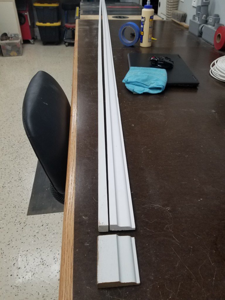
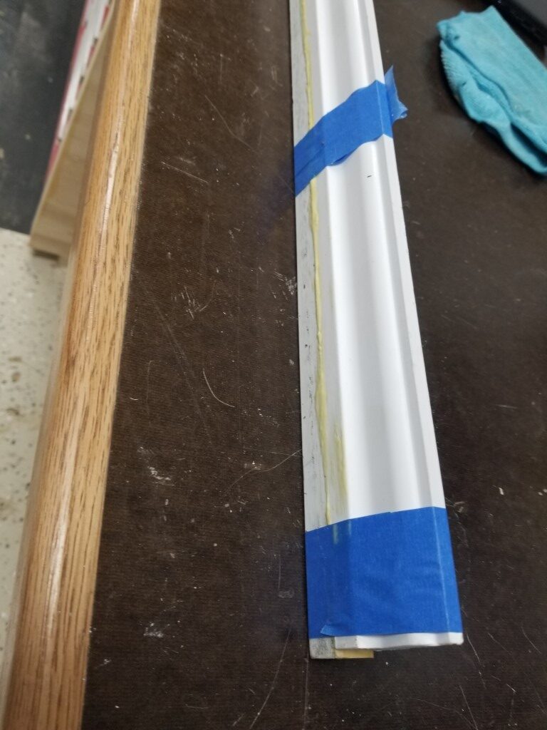
#5 – I was able to find a matching profile on a piece that was too narrow. Since the ‘missing’ part is rectangular it’s possible to just make the missing strip and glue it on.
I’ve used #4 for matching other weird trim on the house, but for this scenario #5 made the most sense. To get a good glue joint I first ripped a bit off of the pre-primed molding to expose the wood. Next I ripped a 12ft scrap of 1x{something} to the right width. Dry fitting the two pieces next to each other showed that the 1x piece was just a bit thicker than the molding. I feed this strip through the planer until it was an exact match and then tightly taped the back sides of the two pieces together, forming a hinge. The tape ‘hinge’ was opened to apply glue and then tightly taped back together. Once the glue dries overnight it will be scrapped, fed through the planer, and then sanded, primed, and installed.
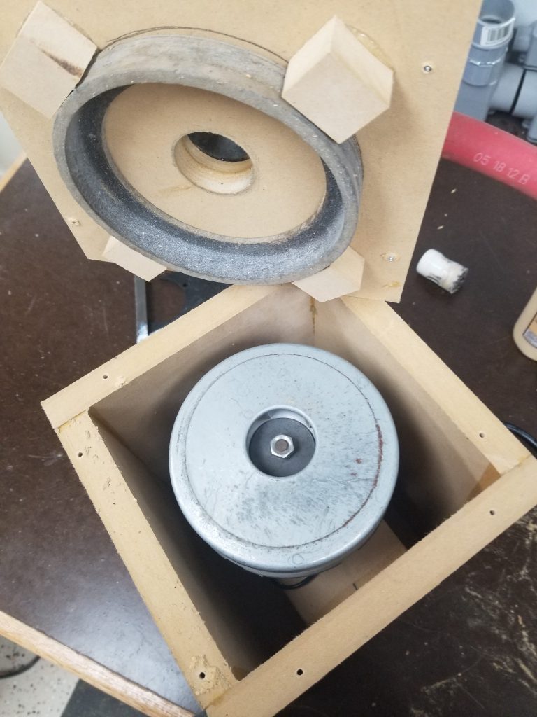
Hacking the Player Piano – Part 1
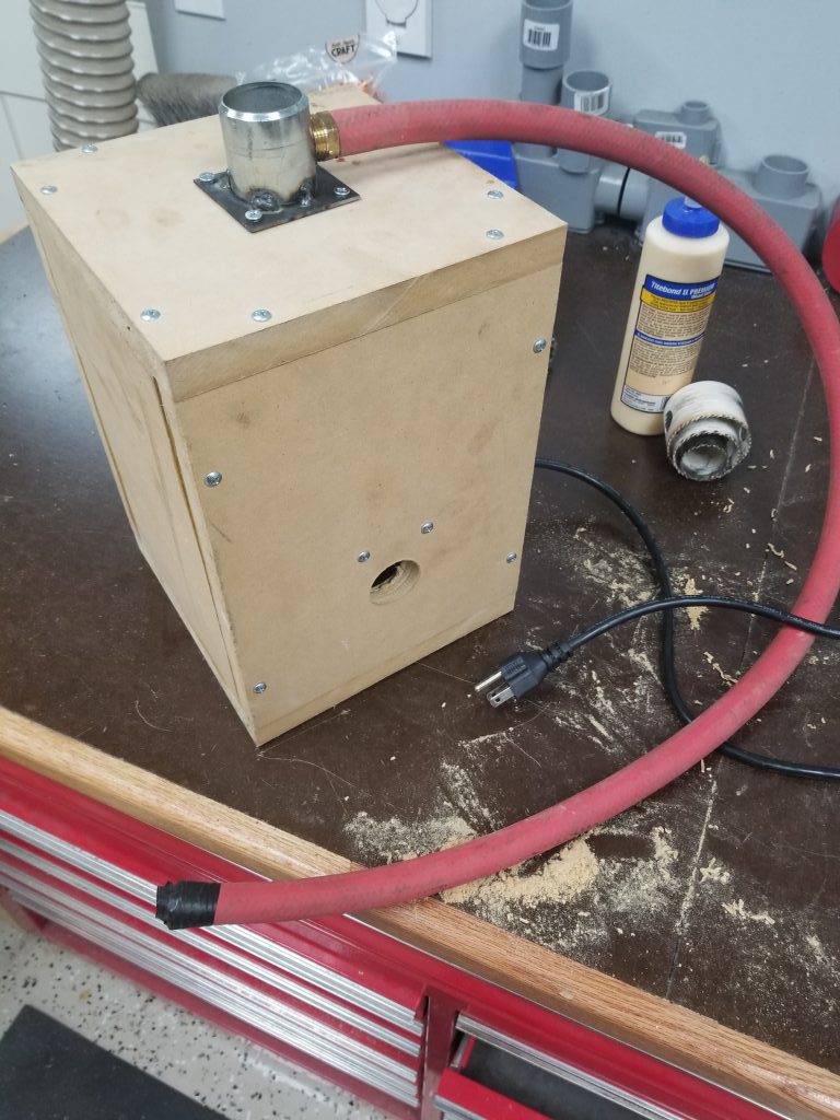
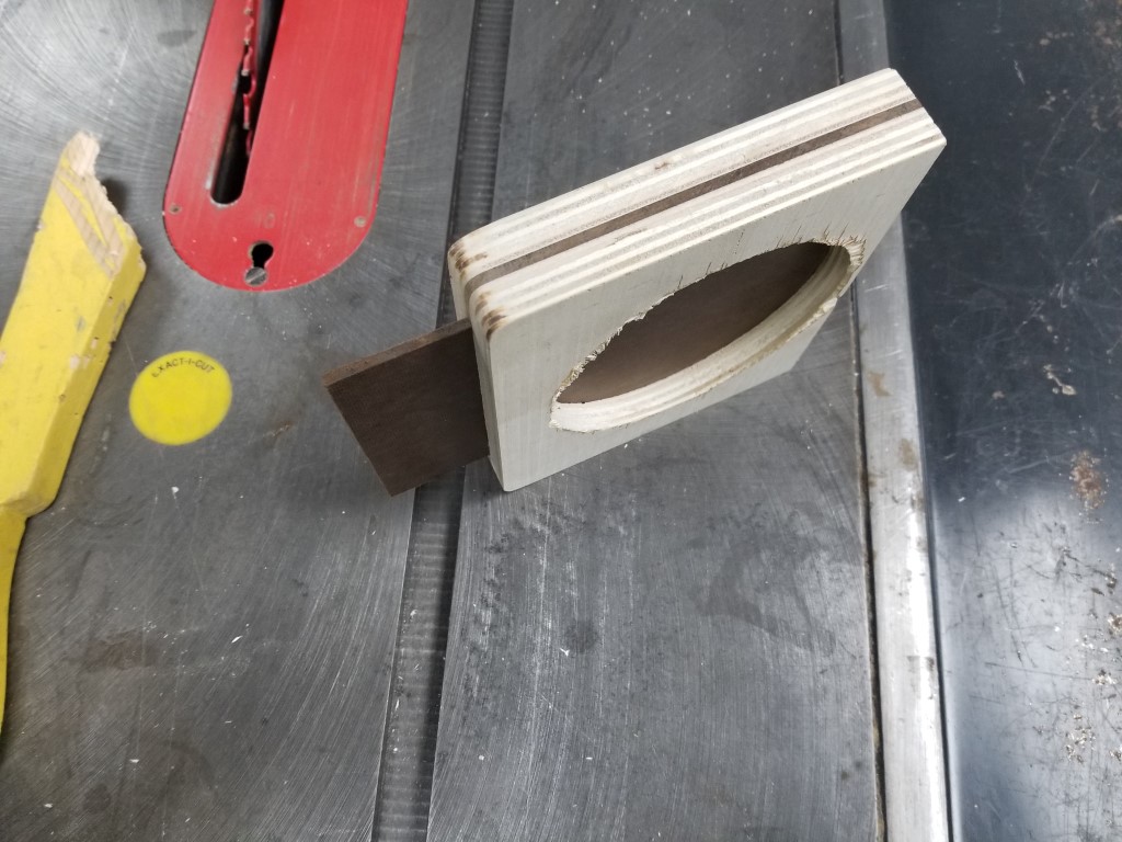
It was only a matter of time before this happened – the player piano (original post) is a real workout to play manually. Since it works on vacuum, I had set aside the motor from an old vacuum cleaner for potential use in powering the piano. Tonight I built a small box to contain the vacuum motor and connect it to the piano. The box is made from MDF, partly because I had scrap that needed to be used, and partly because it’s very heavy & sound absorbing. I made the big fitting by cutting/milling a square from scrap, I then bored a hole in it on the lathe and welded it to a scrap of pipe.
One very large hose goes to the manifold powering all the key bellows, and another smaller hose powers the vacuum motor for the tracker/scroll mechanism. I didn’t notice the smaller connection at first, so I had to go back and tap a fitting into the connection for the large hose; there’s still enough room for both to connect though.
Overall it seems to work great, this effort was definitely a quick proof-of-concept though and I’ll need to go back and fix/test a few things:
#1 – Motor controller to slow down the vacuum motor. Currently it has way more vacuum than is actually needed and slowing down should reduce noise from the motor.
#2 – Ensure cooling is OK. Especially after slowing the motor down I need to test that air flow is good enough to keep the motor consistently cool.
#3 – Mount in piano base and complete further noise insulation.
#4 – Tee hoses (and potentially add check valves) so that manual operation still works.
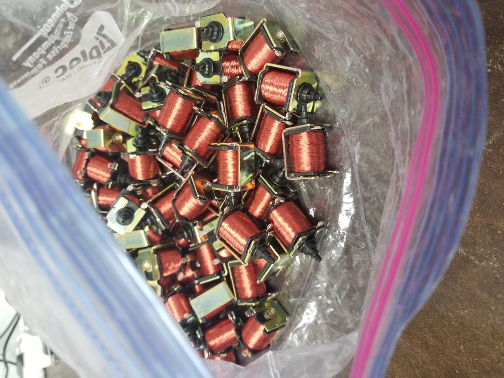
Beyond that I do have plans to eventually (could be tomorrow, could be in 5yrs) automate the player mechanism using some small pneumatic solenoids I found on ebay. These would tee off of each line from the tracker bar and when they open it would simulate a hole in the paper passing by. With this it would then be computer controlled and able to play anything. By default these are off/closed, so the paper mechanism would still work fine, in computer-controlled mode I’d just need to block off the tracker bar holes with some tape.

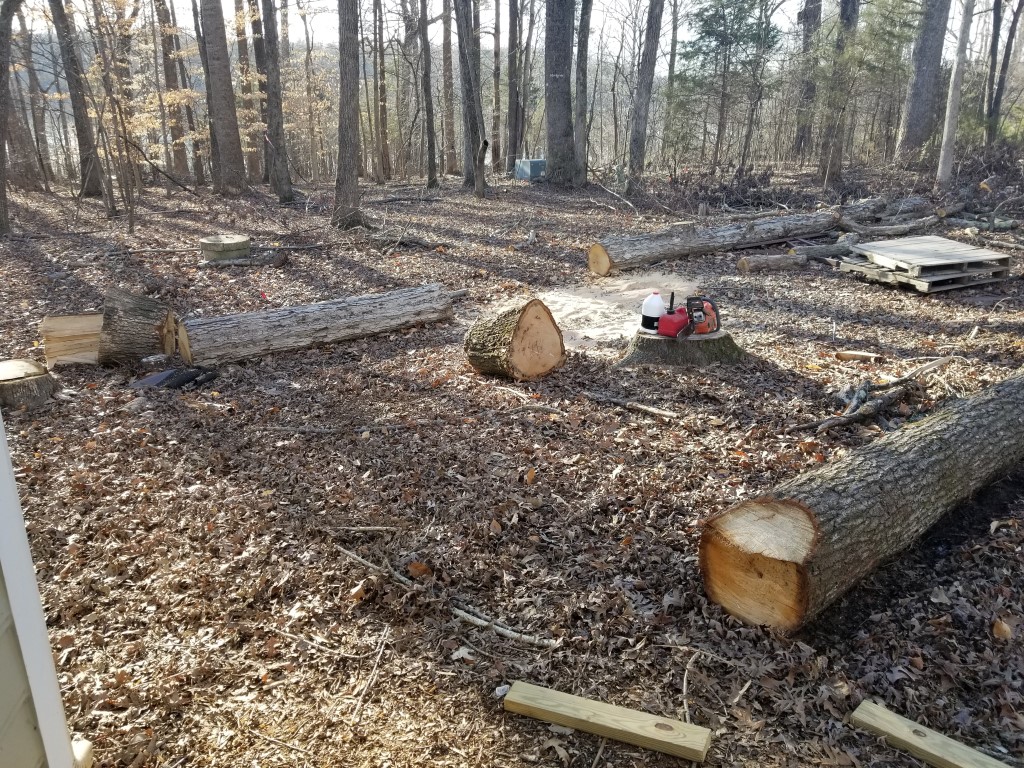
Saw Milling Test
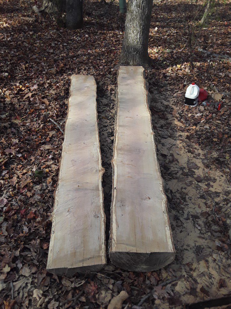
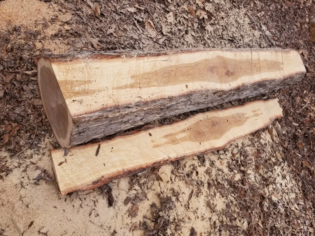
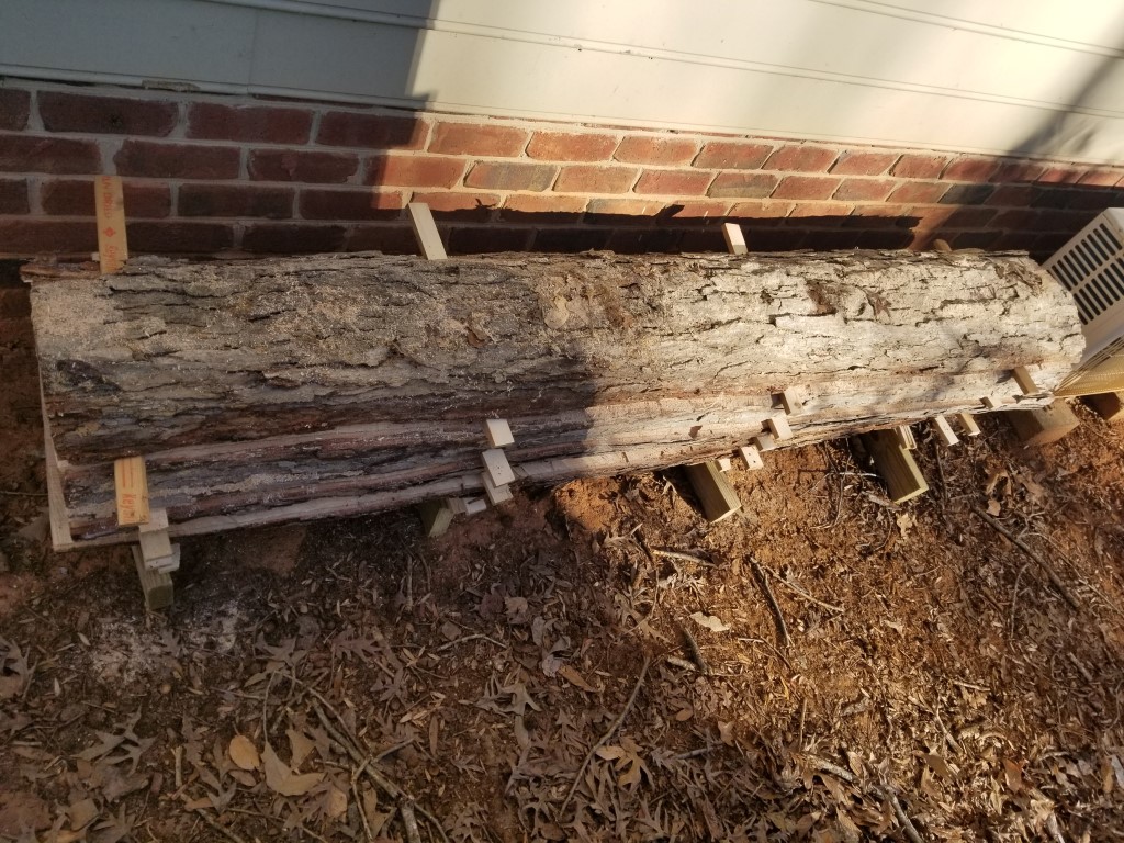
Last fall prior to Hurricane Florence I took down some good-sized white and red oaks. These were great trees but both had large limbs overhanging/threatening the garage, so they had to go. Rather than cut them up for firewood as usual I let them stay where they fell through the winter. Today was unseasonably warm and I took a stab at milling one of the logs. Drying takes a long time, so the point of this was to get at least something started – this way if I don’t finish milling the rest of it for a while I’ll at least have something in the queue.
To make the milling cuts I just free-handed with the chainsaw and there’s a good bit of variance in thickness as a result; to get straight boards I’ll have to deal with this variation at the joining/planing stage. For the next attempt I plan to build a metal guide frame over the saw to allow it to rest level on top of either a ladder laid on the log (first cut) or the level surface made by previous cuts. Also, my saw is a middle/low power model (3HP) and bogged down occasionally. Normal chainsaw chain is meant for cross-cutting and takes too big of a bite for ripping, for the next attempt I plan to modify an old chain into a ripping chain by grinding back some of the teeth – these converted teeth will help clear chips out of the cut rather then cutting themselves and it should mean less bogging down.
Once milled, the log was reassembled with some ‘sticker’ pieces I cut from scrap 2×4’s to create airflow gaps. It’s under an overhang that should provide enough rain protection. The drying happens from the inside out over a long period of time, getting wet from rain only temporarily increases the moisture level on the outside; this dissipates quickly and doesn’t hurt the overall dry time. Drying should take about a year per inch, the slabs are about an inch and a half on average so I may be able to use these as soon as next summer.
We have some ideas for the wood but no immediate plans; this is just a long-term thinking/prep. The white oak is good outdoors and may become some much-needed patio furniture. The red oak may be used to upgrade the fireplace mantel and be used for a headboard and side tables.


Dust Collection
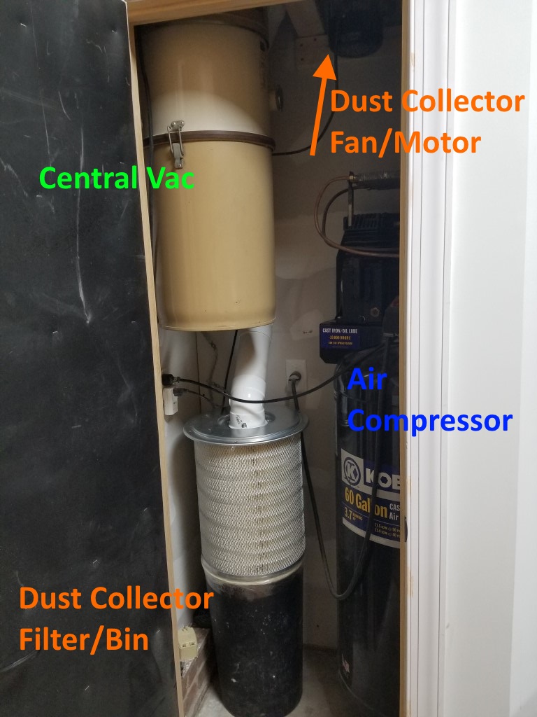
This weekend I installed the shop dust collection system. The system consists of several parts:
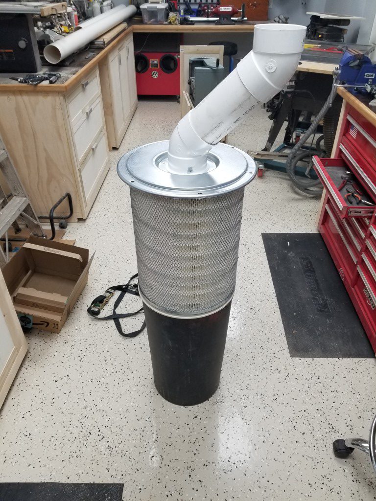
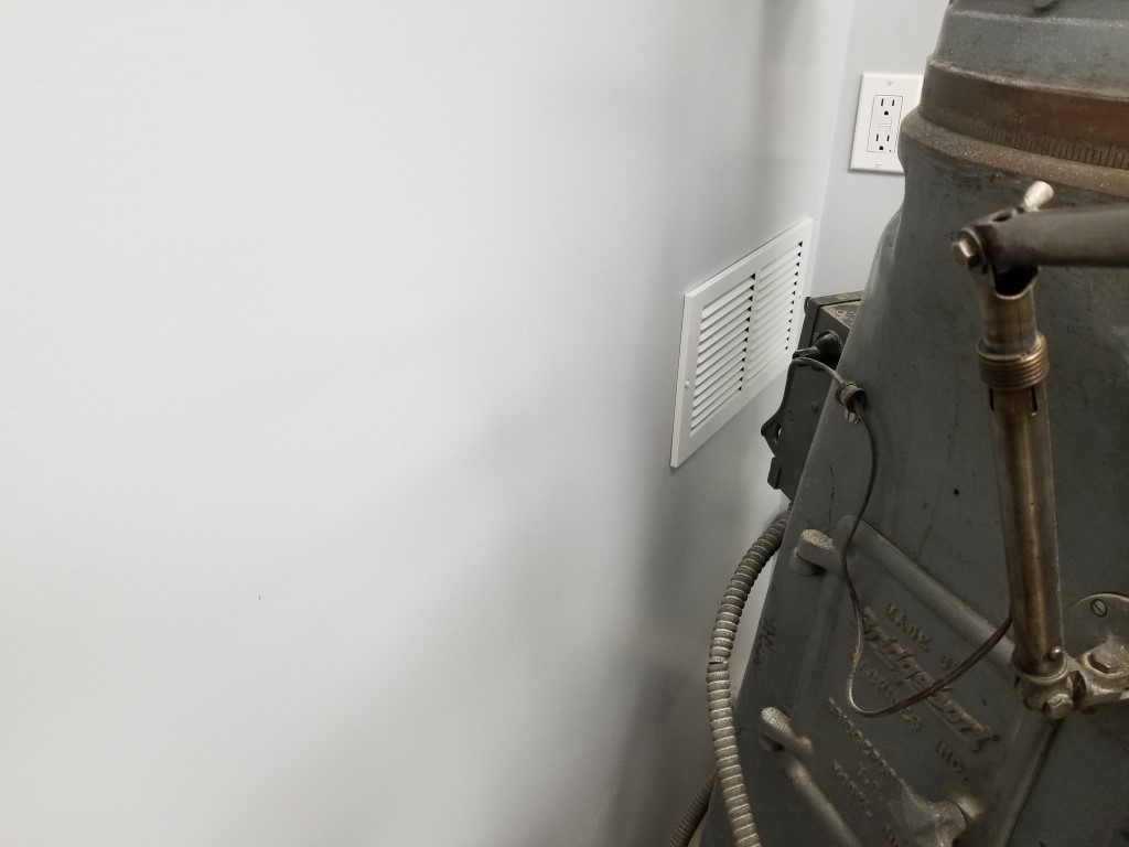
Fan/Motor: I repurposed a portable dust collector fan I’ve had for a while that’s been underutilized (collecting dust, but not as intended). Space is limited in the mechanical room so since the fan won’t need easy access I mounted it high up above the air compressor near where the dust collector pipe enters the mechanical room.
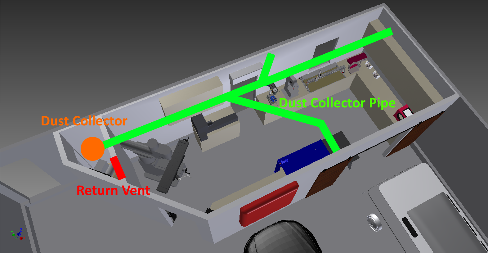
Pipes: 4″ PVC DWV pipes; there are a few branches leading to the different tools. I tried to keep the overall length as short as possible and the bend radius’s large.
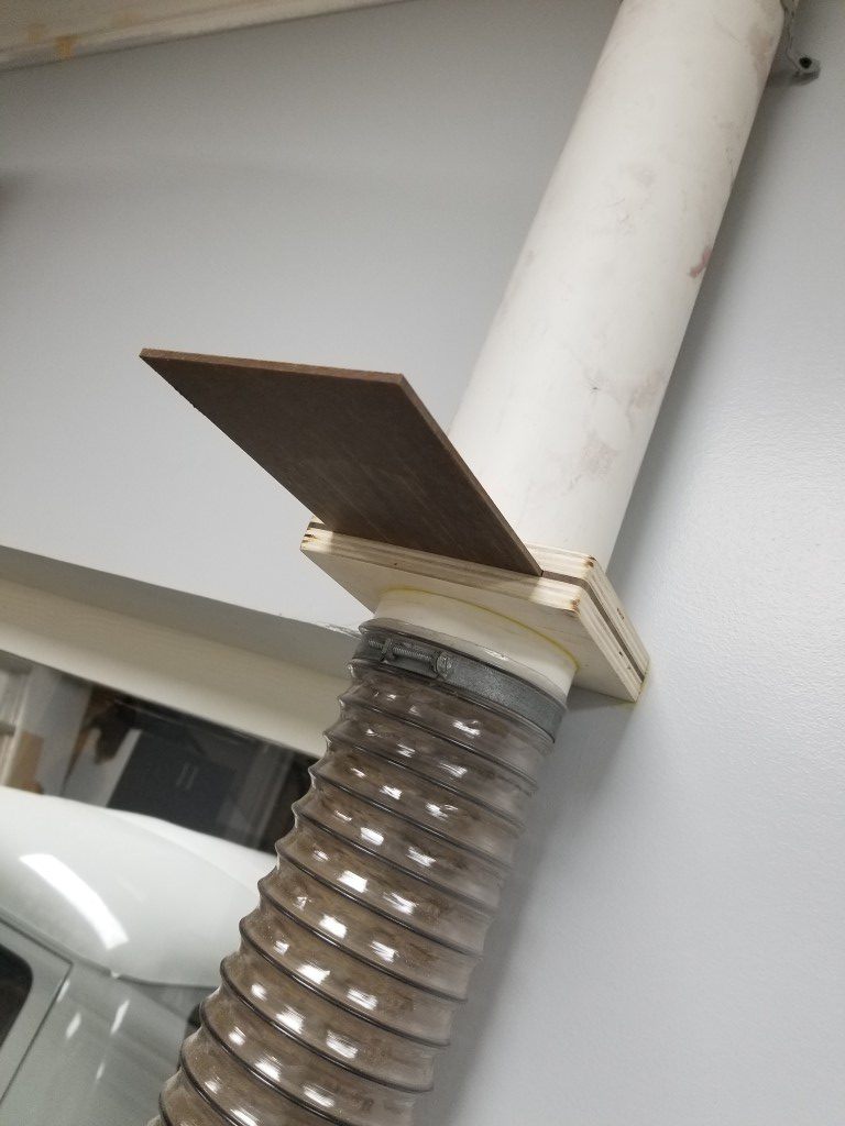
Blast Gates: The blast gates control the air flow though the system by blocking off unused branches. I made these with 1/2″ plywood and 1/4″ hardboard. Circle cutouts were made on the lathe to match the pipe outside diameter exactly.

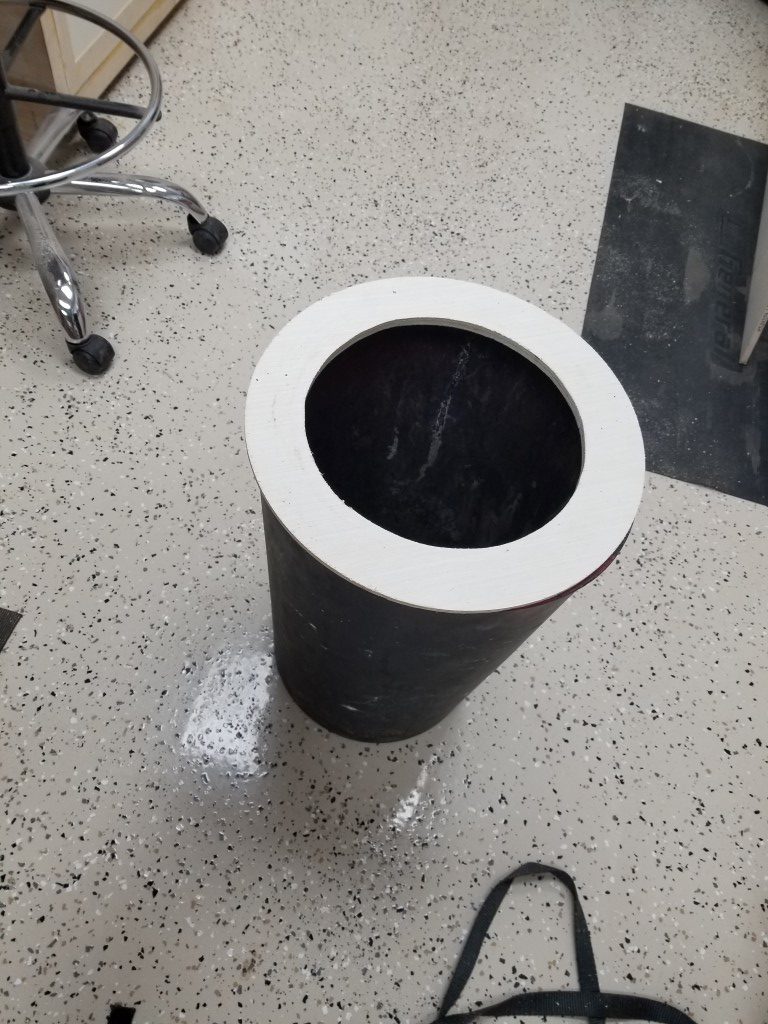
Filter and Collection Bin: The portable dust collector came with a light canvas bag that restricted the air flow massively while still allowing fine particles to escape. To improve this I replaced the bag with a semi truck air filter mounted to a trash can. The theory is that air will exit the filter and larger dust/chips should fall into the trash can below. There are purpose-built dust collection filters available, but the costs are much higher for these and the semi truck filter has the same specs; different economies of scale. To mount the filter to the bin I made a plywood ring, for now they’re just taped together but I may add latches at some point. The design may need some tweaking; I’ll know more after it gets further use, but for now the airflow is excellent.
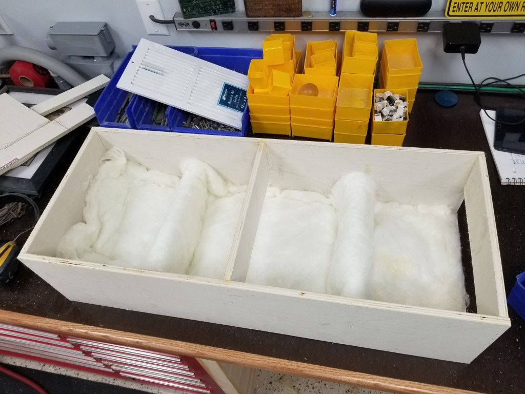
Return Vent: Having the collection bin in the mechanical room created a problem; the mechanical room is well sealed for noise reduction, so there was nowhere for the air exhausted from the filter to go. For heat/air to be retained in the shop, the exhaust air needed to return to the shop via a vent. Since I also wanted to keep the mechanical room noise level as low as possible this meant the vent needed to be sound proof. I built a sound proof vent by creating a 3ft long box and offsetting baffle plates inside of it. The sound has to reflect a dozen or more times off of the baffle plates; at each reflection it gets absorbed some by a fiberglass lining. The air, however, is able to snake around the baffles and find its way out. The inlet to this vent also points directly at the floor away from the sound sources. Somehow after adding this vent the mechanical room noise is actually noticeably quieter than when it was completely sealed. I think this may have had to do with the air pressure changes resonating in the previously sealed room, whereas now any fluctuations are equalized through the vent.
Control: For now control of the system is via a remote control outlet (repurposed from controlling the vacuum at the old shop), at some point I may integrate some low voltage switches with the blast gates so the motor will turn on as soon as any gate is opened.
Planer Cart
(I’ve had this built for a while now, but I’m catching up on documenting shop progress tonight)
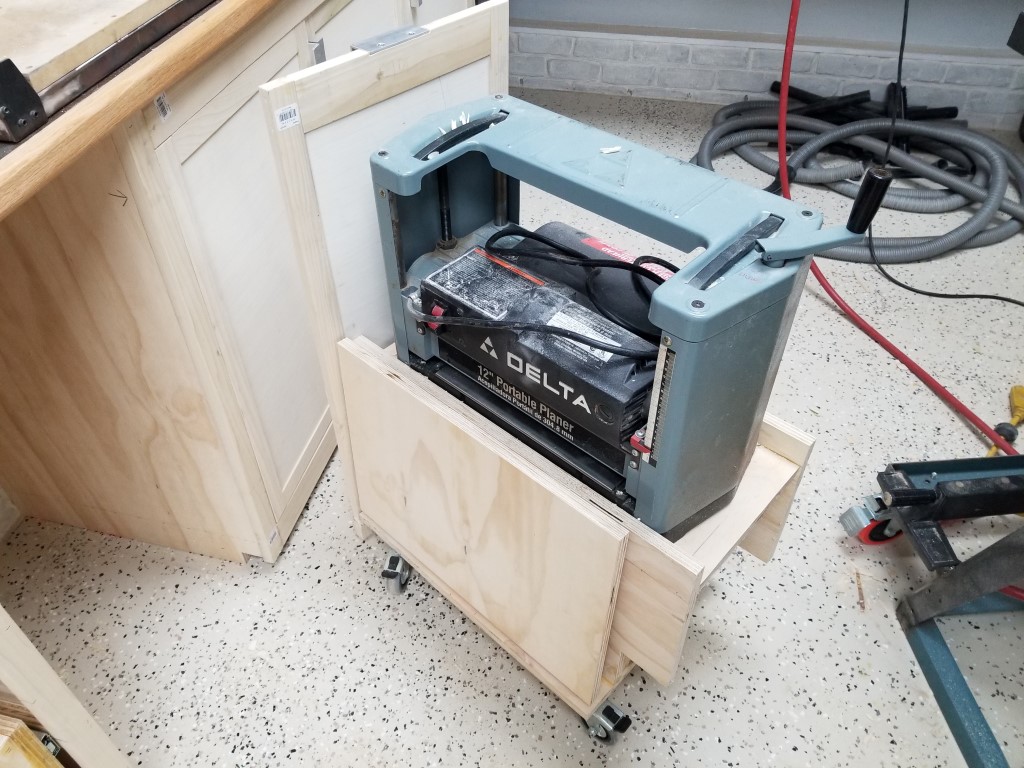
A while back I got an old Delta ‘Portable’ power planer at a garage sale; it’s helped out in a few projects already so I thought it deserved it’s own spot in the shop design. The planer requires a fair amount of space for it’s infeed and outfeed to keep the material flat, however the planer isn’t used enough to justify keeping it out on the workbench permanently. I also wanted to avoid the need to lift it out of a cabinet, so with this in mind I came up with the cart below that integrates with the cabinets. The cart rolls on double-locking casters and has folding infeed/outfeed tables that align with the planer’s table when upright. I used ‘drop leaf’ style hinges/supports to allow the tables to lock in place.
The ‘dead’ space inside is currently holding the router and router bits; I may convert this to a drawer at some point. When the cart is stored it just looks like any ordinary cabinet door.


Shop Cabinets
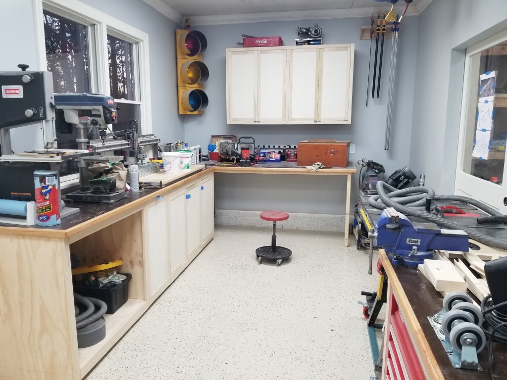
This weekend I resumed work on the shop and made major progress on the cabinets:
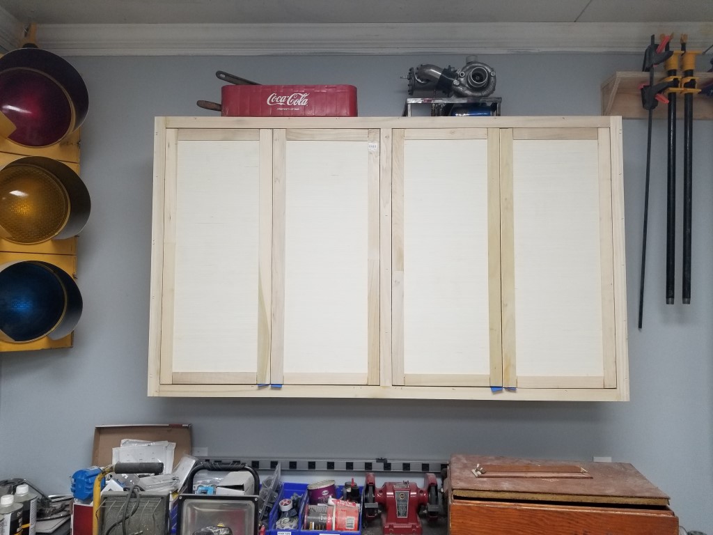
– Upper cabinet built
– Another cabinet built for small parts storage
– Doors for existing base cabinets built
The doors are ‘shaker’ style for simplicity; building these is as easy as cutting a piece of 1/2″ plywood to the right size and then wrapping it in the same 1×2 poplar used for the cabinet face frames. All the door frame pieces got a 1/2″ dado to fit around the plywood edge and then the top/bottom frame pieces had 1/8″ removed from either side of their face on the ends to make a tenon. I found that the majority of the build time is in changing between the various setups needed (cut to length vs dado cutting vs tenon cutting vs cutting plywood, etc) so after the first test door I tried to build as many doors at a time in parallel as possible.
I went with ‘inset’ mounting of the doors because i like the clean/simple look. This gives a lot less room for error compared to overlay mounting since the gap is visible and it and needs to be small and consistent. It’s critical that cuts are within 1/16″ and that everything stays perfectly square or things go downhill fast. For the dados I used an old ‘wobble’ style dado blade (these are so sketchy they’ve been banned in europe); the geometry of this contraption is such that it can’t leave a perfectly square bottom. It’s not really a problem since the dado bottom is internal/unseen, but it made measuring and setting the correct dado depth difficult.
I definitely had a few mistakes to correct along the way, but overall I think it was just enough of a challenge to help improve my woodworking. Next steps are to make handles, make/install drawers for the last open base cabinet, and (eventually) do the finish work of filling/sanding/painting.
Small Parts Organization
Background:
The new shop has given me the opportunity to rethink storage of the miscellaneous small parts I have laying around: nails, screws, nuts, bolts, brackets, cable ties, electrical connectors, fittings, etc. The previous system I had was to sort by type (i.e. nails) into individual plastic shelf bins (the common Blue/Red/Yellow type). This was better than nothing, but the downside was that every time I needed something I had to dump the whole bin into a sorting tray and search.
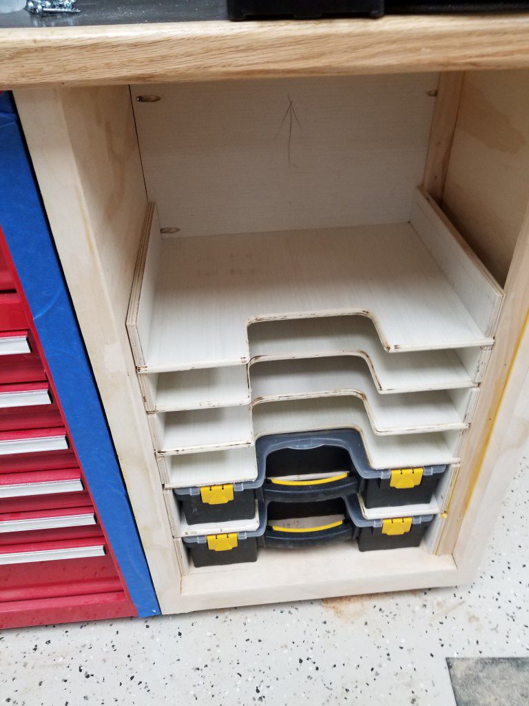
The new method uses a rack of portable parts storage cases. These cases give the ability to sort by main type (i.e. nails all in one case) but also by individual size (i.e. 1″ finish nails). The cases also have removable bins inside of various sizes; by swapping these around I’ll be able to optimize storage – swap bins between the cases that have more big parts vs those that have more small parts.
I considered the individual drawer style of parts organizers also; when I’ve had these in the past it seemed like I was constantly opening and closing the tiny drawers to look at parts from above; the drawers also easily jammed closed when full. The parts storage cases should prevent both of these problems.
(There are lots of similar projects online that sparked the idea, so this definitely isn’t something I can take credit for coming up with.)
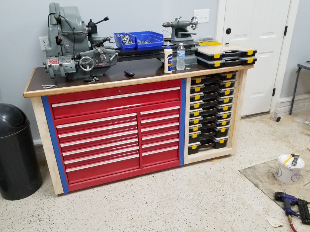
Construction:
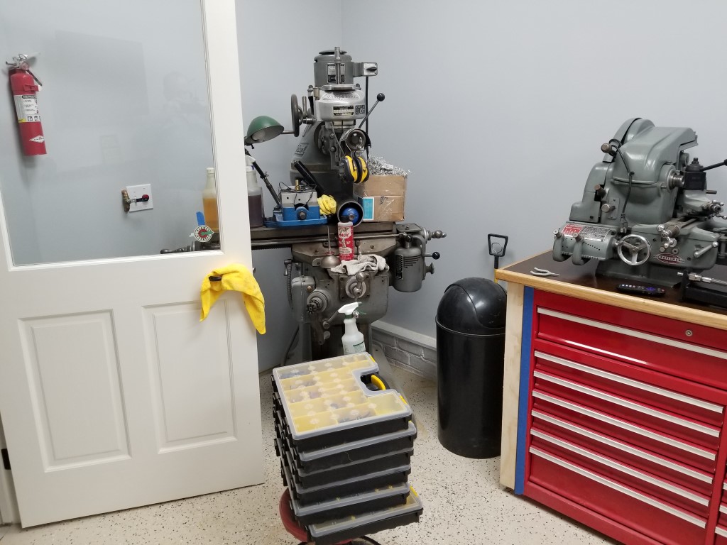
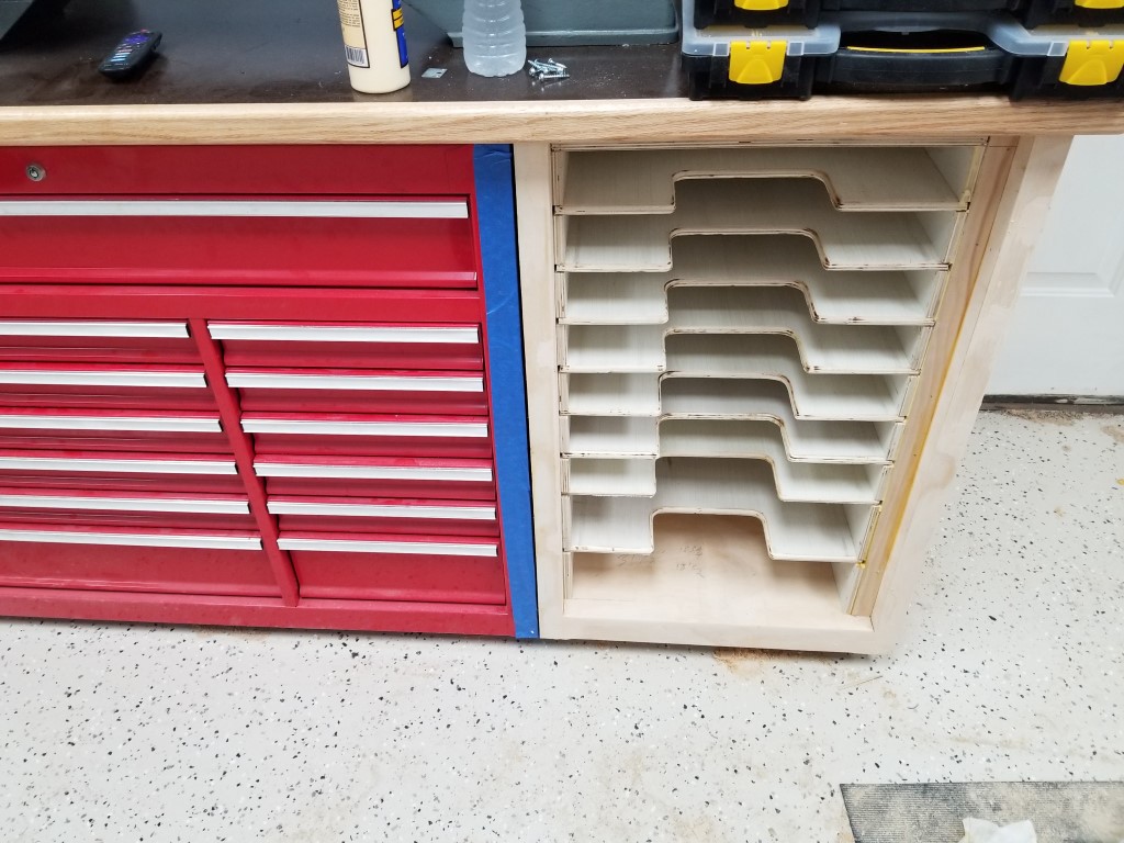
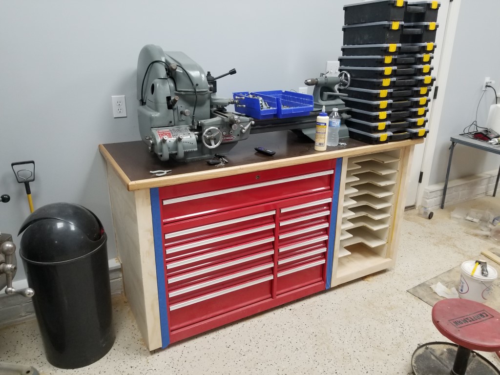
Last weekend I built a cabinet to house the ‘machinist’ toolbox used for the mill and lathe tools; the cabinet also supports the lathe itself. For the countertop I’m again using the “Norm Abrams” design – plywood topped with a varnished hardboard layer that’s cheap/easy to replace when it gets too beat up; I had these at the last shop and they worked really well. I left room in the cabinet for this parts organizer idea, so today I just needed to outfit it with shelves to support the parts cases. The rack consists of the shelves themselves as well as spacer blocks that help support the shelves and make it easy to get the correct spacing. The process for making the shelves was as follows:
- Rough cut each shelf from the plywood panel with a circular saw.
- Square and cut the shelf to final dimensions on the table saw.
- (For the first shelf) Drill holes at the corner of the handle area and finish cutting it out with the bandsaw.
- (For all other shelves) Clamp the shelf to the first shelf and trim out the handle area area with the flush cut router bit.
- Run the router over both front edges with a 1/4″ round-over bit.
There’s now an empty space in the cabinet behind the cases that I may eventually tap into and repeat the same idea using the smaller version of the cases; this would be accessed from the side of the cabinet, but for now it’s not needed.
I intentionally got a couple extra cases. This allows more options for swapping around internal bins, but primarily it’s so I have backups in case a case ever gets broken and exact replacements are no longer available.
All that’s left is to add an inset door (the cases are offset to the left to allow room for a door and hinges on the right), a slide-out platform at the top, and then finish trimming/sanding/painting everything.
(I also finished and painted the walls/trim then ground and epoxied the floor over the last several weekends, but I forgot to get in-progress pictures.)