-
Recent Posts
Recent Comments
Category Archives: Uncategorized
Custom Desk – Design & Build Start
The office project is coming along well and the last major missing piece is a desk to replace the table we’ve been using.
Before starting this project we planned that the cabinets would cover the room’s exterior walls between the windows and we also left space on the interior wall for misc stuff (file cabinet, chair, etc). This left the center of the room largely open and it made sense to have the desk there. This arrangement provides some advantages: #1 sitting at the desk in the center allows facing out towards a window with a view up the driveway instead of just looking directly at an interior wall and #2 any screens on the desk will face an interior wall instead of the windows, minimizing glare.
Unfortunately the desk-in-the-center arrangement has one big drawback in that having monitors placed on the desk essentially forms a ‘wall’ of sorts in the room. Normally I wouldn’t care about this so much, but the office is directly adjacent to the foyer with a double-width door opening between the two – so it needed to look as good as it functions. The solution to this problem is to hide the monitors in the desk with a motorized lift mechanism.
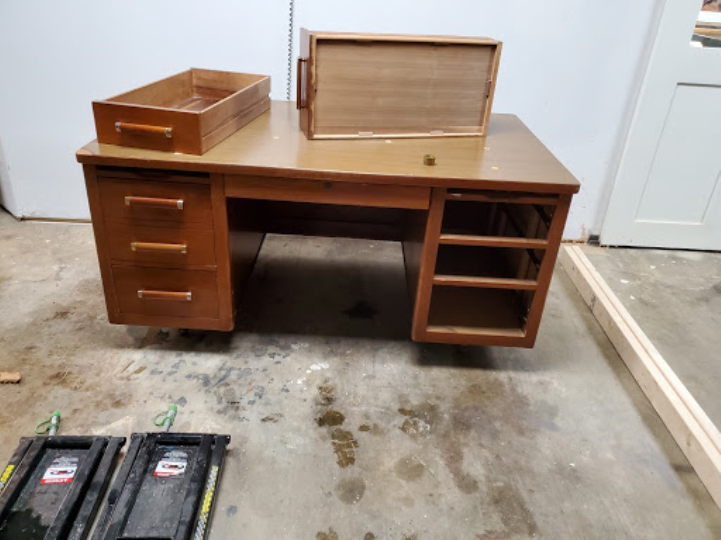
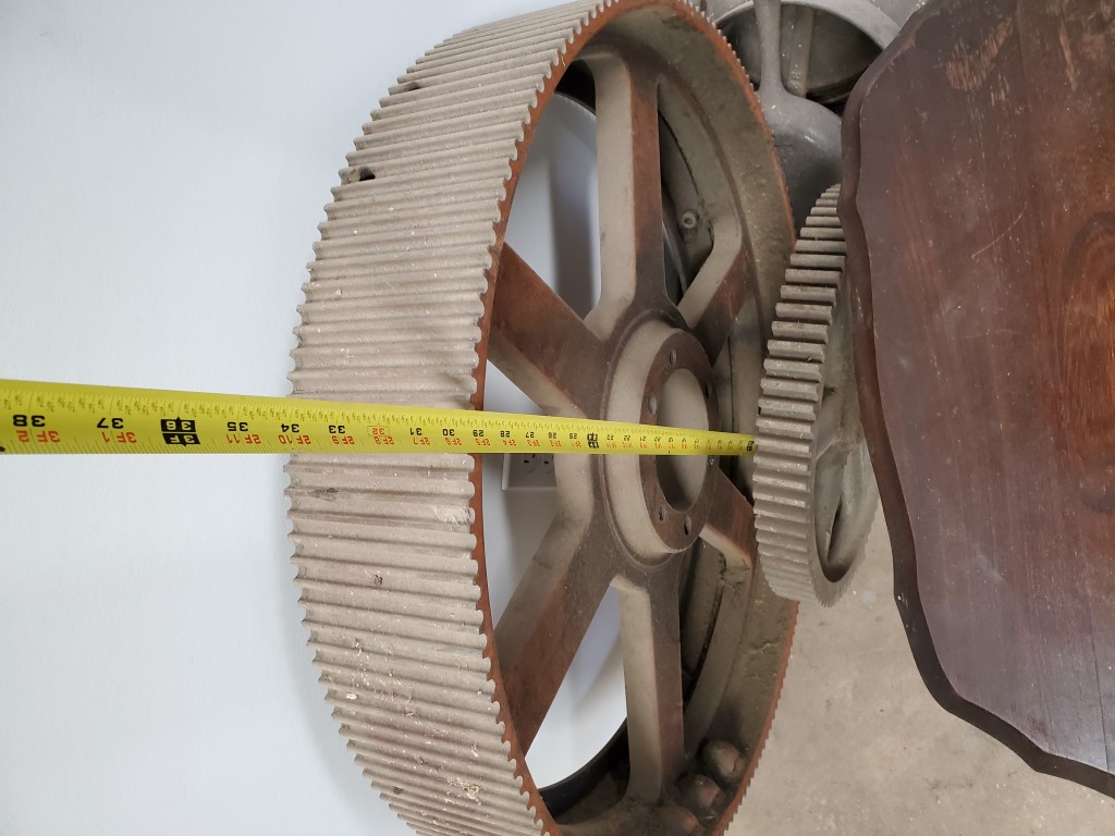
We found a desk at goodwill to use as the starting point – the base is good quality hardwood but the top is/was a laminate slab that I’ll replace. We’ve also had a large gear waiting for the right project to come along. The plan is to remove one of the desk’s towers, replace it with the gear, and then make use of the existing back panel of the desk to enclose some space for the monitors.
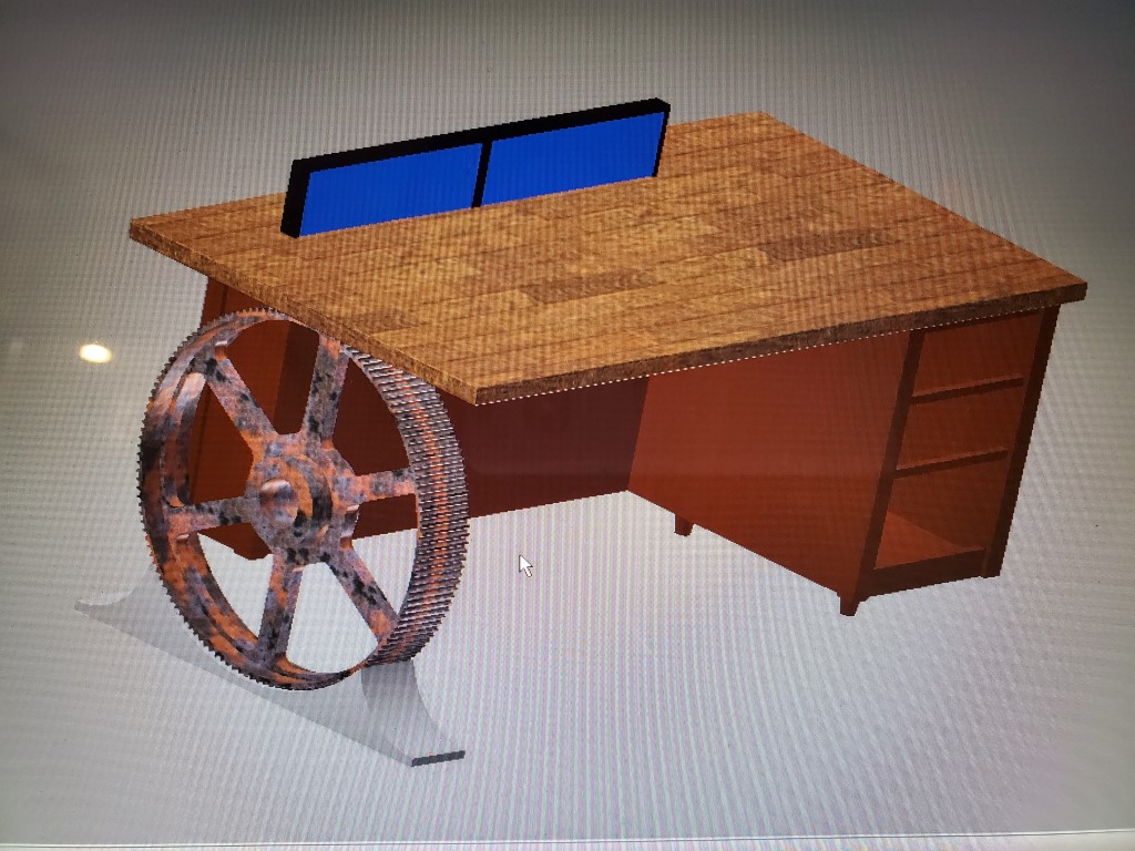
I started with disassembly of the desk, and then I copied two corner pieces and added some 1/4″ plywood to form the monitor compartment. The new parts are made from Cherry which seems to be an OK match for the existing wood.
Next up I need to add some more internal structure to the monitor compartment then strip/sand the desk exterior and begin on the lift mechanism.
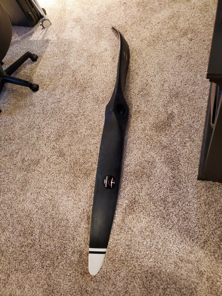
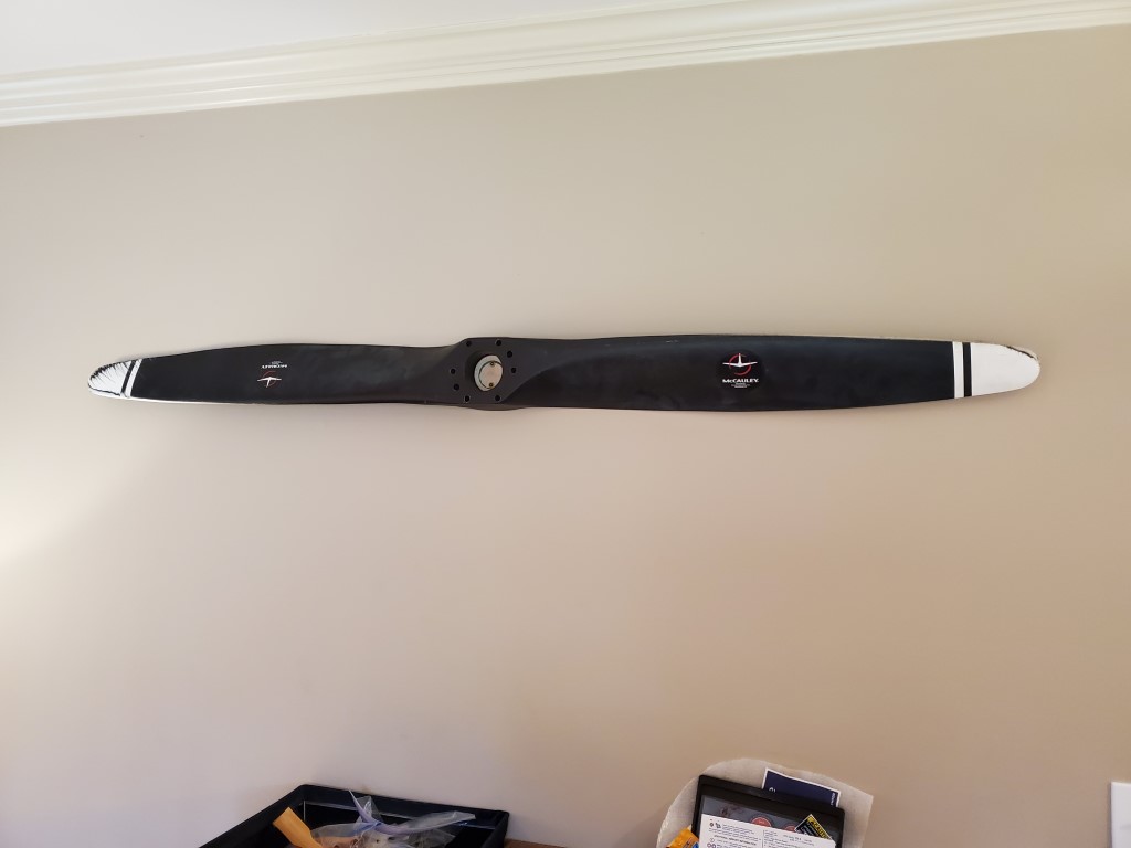
Prop Straightening
Continuing with the home office/study/library build, I found some decoration via a damaged airplane propeller. I was able to straighten it out using the press and some 2×4 blocking. The aluminum is springy so the key to getting it flat is to bend a bit past flat, just enough so that when it springs back it’s straight.
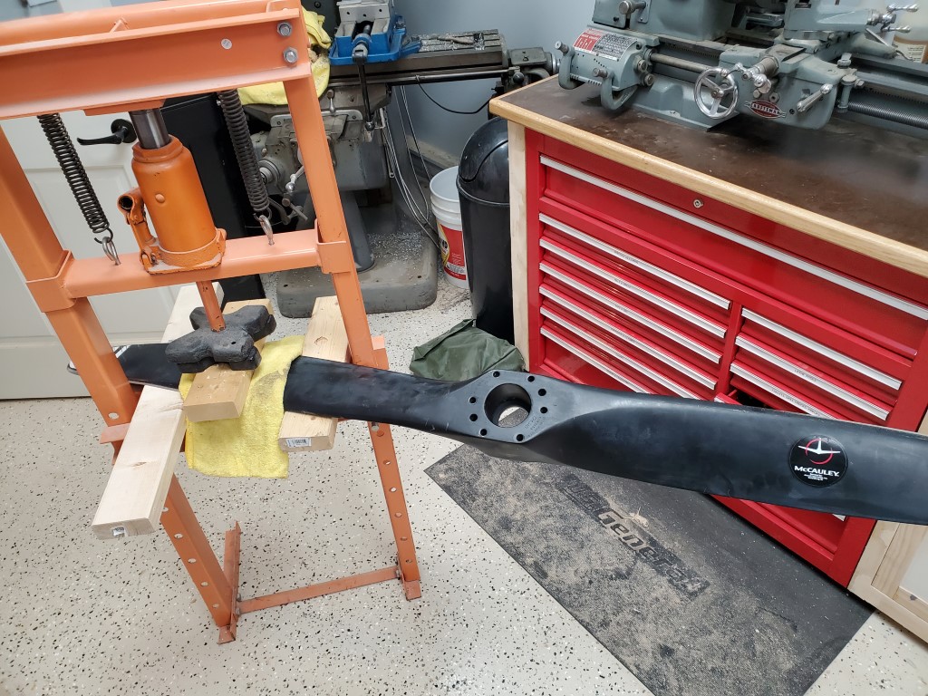
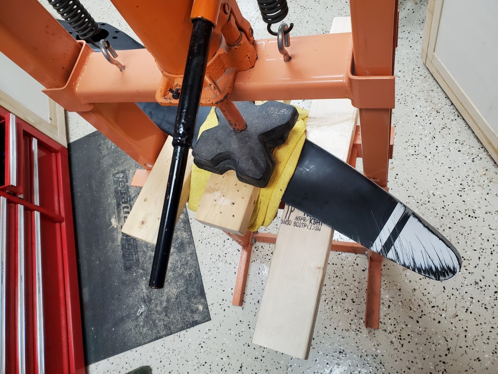
There was a possibility that the amount of bending needed would create cracks. Based on prior experience with aluminum, I would expect for the paint to flake and for the surface underneath to turn white just before cracks occurred and I was looking out for this. If cracking had started, the plan was to heat the area with a torch until it was annealed, then continue bending – this would also have required repainting, so I’m glad it wasn’t needed.
For mounting it to the wall I cut a circle of 3/4″ plywood on the bandsaw. The circle is just small enough to fit into the prop hub, but too big to go through the smaller hole of the inner hub. Long cabinet screws then secure the plywood to a stud, sandwiching the prop in place. I plan to make another circle, paint black, and fit it into the hub to cover the structural piece.
Oak Butcher Block Counter
At the end of last year I replaced the cabinet doors in our mudroom. Since we wanted to swap from half-overlay doors to inset doors and from raised panel style to shaker style, it make more sense to build new doors than to rework the existing ones. The new doors were to be painted, so I used poplar rather than ‘waste’ the oak from the existing doors. All this to say, I’ve had a big pile of scrap oak sitting around from the old mudroom doors waiting for the right project to come along.
Fast forward to present day, and I’ve started building cabinets for the office. These will also be painted, so are mostly made of poplar and cabinet ply. One section of the cabinets will be a hutch with some counter space. After considering counter options for a while it eventually occurred to us to use the scrap oak to construct a butcher block for the counter. In addition to the scrap oak I also had the oak from the saw milling tests that could be used to ensure coverage.
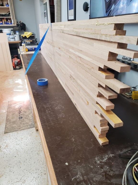
To start the build I sent all the scrap oak pieces through the planer to remove the stain/varnish layer on each side, and then I ripped down everything that wasn’t already 1.5″ wide (though most pieces already were). There were a few different thicknesses involved since the wood from the door panels was a little thinner than the wood from the door frames, and the wood from saw milling was a little thicker than the rest. The variation in thickness isn’t a problem though as long as all wood pieces of the same thickness are kept on the same row. It is very important that all pieces in the same row are planed to the exact same thickness to ensure no gaps.
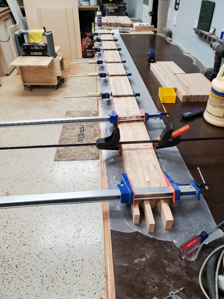
I laid everything out first to make sure the pattern would cover the size needed. For the edge that would face out I used a piece of store-bought oak that I had leftover from making the shop work benches, this piece was long enough to cover the entire length of the counter so that no joints would be on the edge and so that the edge would have a consistent thickness. With the layout confirmed, I then I glued up about 1/3 of the width in 3 sessions before then gluing and clamping those sections together. I used a solid roller/brayer to spread the glue, all together about 1/2gal (!) of glue was required.
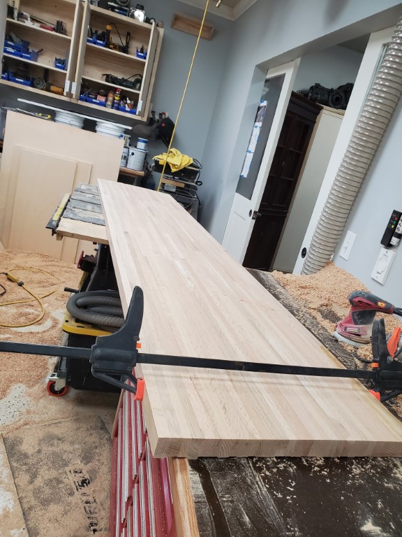
After the glue dried I planed the top flat with a handheld power planer and cut the ends to length. I then further fine tuned the flatness with a belt sander before a final sanding with an orbital sander. The slab then got a medium stain (Early American) to even out the red oak’s color variation a bit, followed by wipe-on poly.
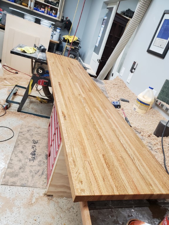

This is a situation where a similar slab could be bought for less after considering the time spent. It’s neat though to have a custom piece that encapsulates some history of the house as well as solving the ‘problem’ of getting rid of the scrap oak (I’d never throw it away and it was taking up a lot of room); so altogether I’d say it was worth the time spent. Planing created a mountain of sawdust and before the next big project involving the planer I need to make a dust collector connection for it.
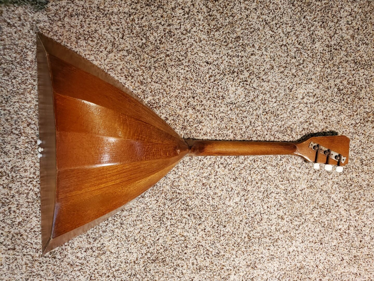
Balalaika Repair
It had been in storage and a few parts were missing that needed to be replaced:
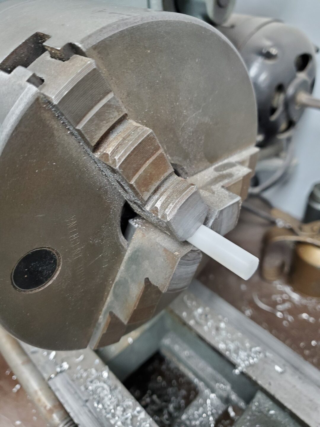
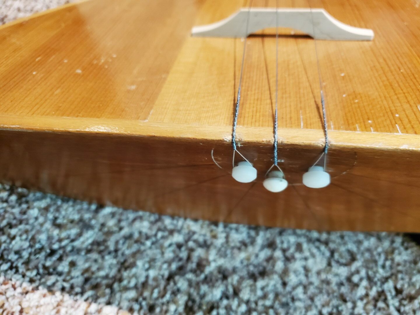
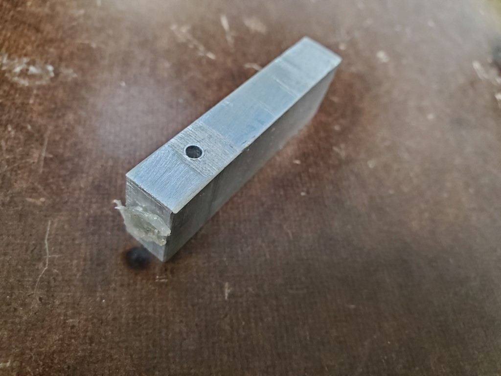
– End Pins – 1 of the 3 end pins remained and I used it as a reference for turning 2 more matching pins on the lathe from a plastic rod.


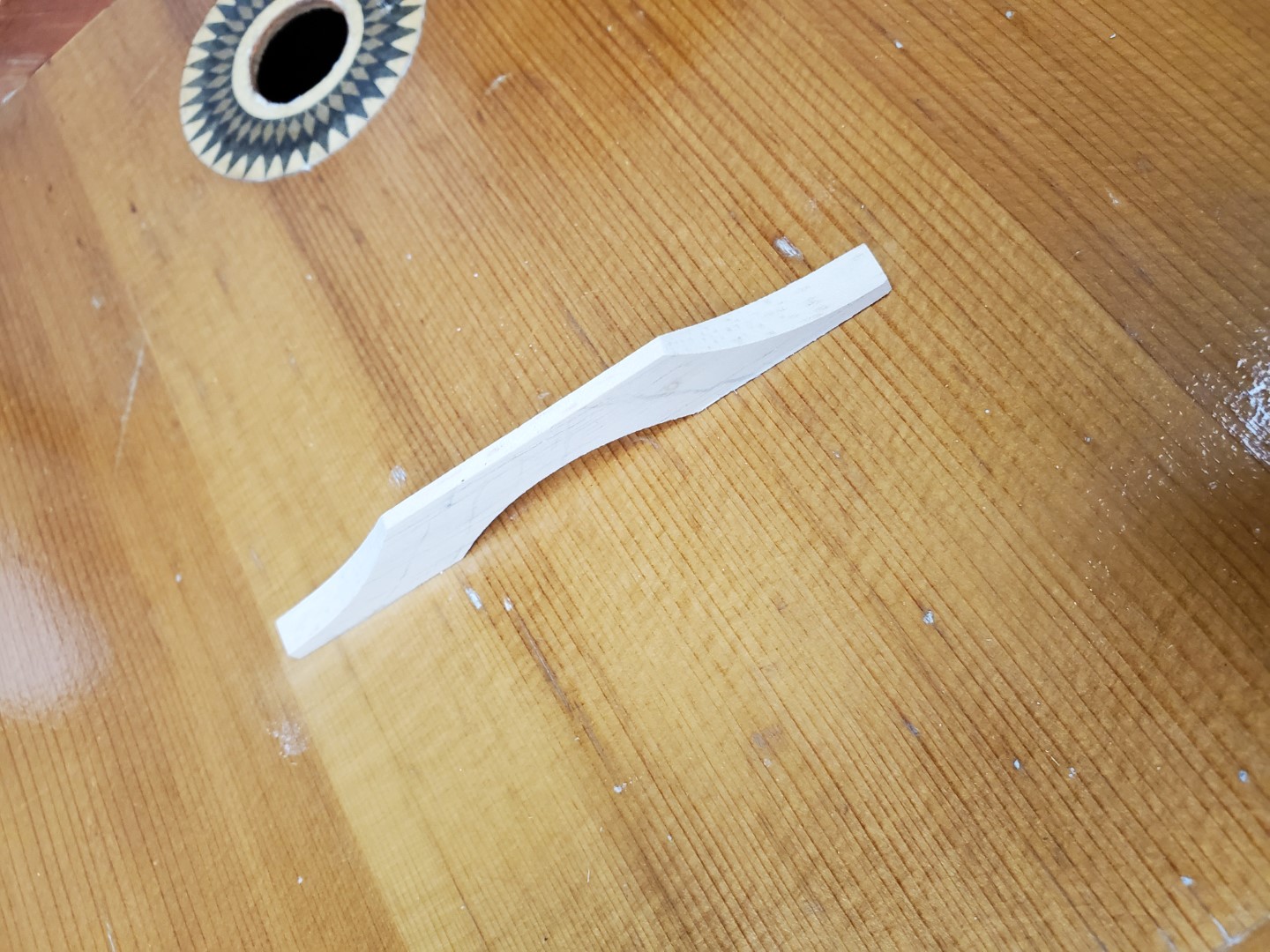
– Bridge – The bridge was missing but I found dimensions that seemed to match the shadow that had been left by the original bridge; I used these dimensions and some reference photos online to make a replacement out of a scrap of maple. This was very quick work with the belt sander.
– Strings – This was the easiest part, available online.
With the parts replaced we were able to tune it and it seems to play OK…

With an endoscope camera I was able to find two labels inside:

Left Translation: Balalaika. Article #205. Airbrush method finish. Nationwide Standard of Russian Soviet Federative Socialist Republic 83-72. Price 6 rubles 70 kopeks. Leningrad, 15 Chapaev St.
Right Translation: Ministry of Local Industry of Russian Soviet Federative Socialist Republic
Main Directorate of Production of Musical Instruments
Lunacharsky Factory of Folk (plucked string) musical instruments
Leningrad
The left label is also stamped with a 1973 date
Apple IIc Video Repair
Since moving, the home office area has taken a back seat to other projects. Although it’s been fully functional, there were many unopened boxes filled with books/computers/etc. This weekend we started the process of unpacking and organizing the office stuff with the goal of understanding what kind of storage space and desk space is needed. I’ll use this info to design/build cabinets, hopefully some time in the near future.
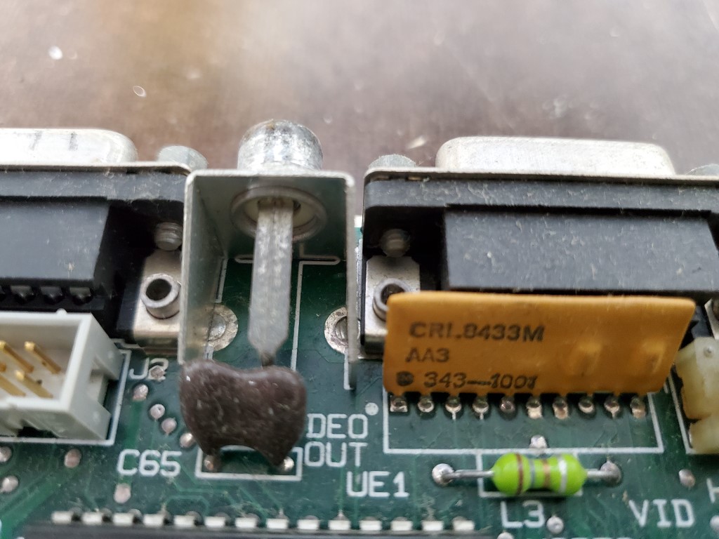
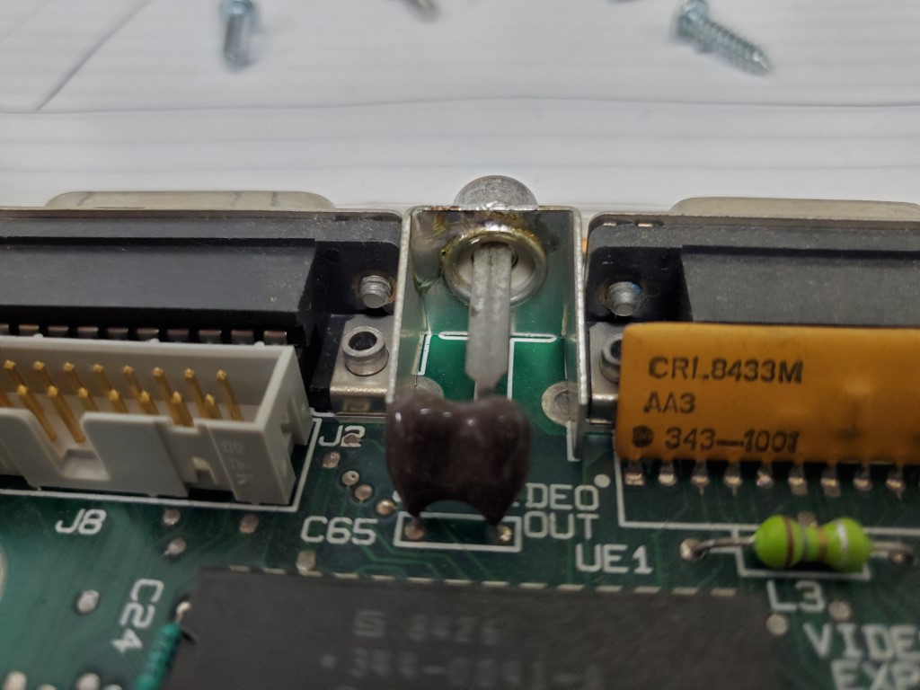
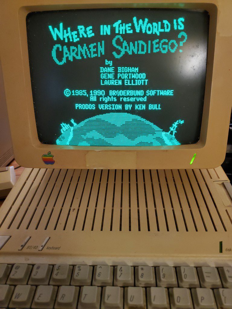
One of the boxes contained an Apple IIc. It powered on OK, but the video signal was flaky. The video connector felt a little loose, so I opened it up and found that the connector design relied on a crimped connection that had worked loose over time. With a very hot soldering iron I was able to heat the crimped connection and flow solder into the joint.
This fixed the video problem from the IIc side, but on the monitor side the brightness knob has to be set just right or the picture scrambles. I suspect the brightness potentiometer has oxidized everywhere except where the wiper was sitting for the last 20yrs. If this is the case, then I should be able to fix the monitor by just spending some time turning the adjustment knobs back and forth until it clears up. Either way I’ll be disassembling both the monitor and the IIc (again) to fully clean them and reverse the yellowing of the plastics; I can replace the potentiometer at that time if needed.
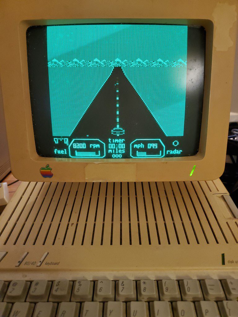
I’m planning to set aside a corner of the office for the retro computers (Apple IIc, Macintosh Plus, Commodore 64). As I unpack these I’ll post more details on getting them cleaned up and working again.
Piano Automation – Valve Control Board
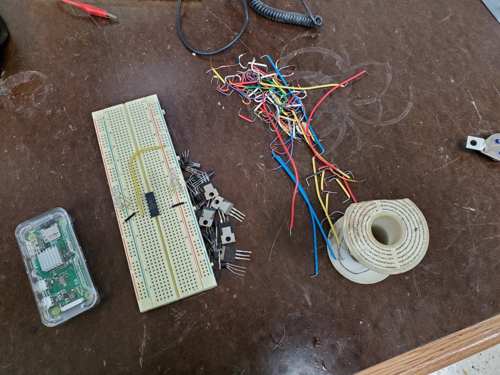
The Piano controller will be based around a Raspberry Pi Zero W. I had originally considered using a spare Arduino, however since the project will require a lot of file handling and a web server, having a full general purpose OS is much easier than shoe-horning it all into the Arduino. The Raspberry Pi also has a wifi adapter built-in, simplifying wiring.
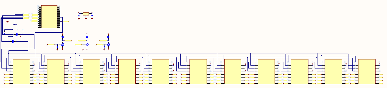
Unfortunately the Raspberry Pi doesn’t have the ~90 outputs that are needed to control the piano’s valves. This is a common problem in electronics and micro controllers – it’s assumed that the designer/integrator is going to provide their own output channels that are most suitable for their device. Instead, the Pi has several low voltage/current outputs that can be switched extremely quickly. I’ll connect these outputs to shift registers, clock all 88 valve bits into the shift register’s ‘memory’, and then send a signal to latch these new values to the outputs. This will be repeated quickly enough (~1000 times each second) that for my purposes the ‘remote’ outputs at the shift registers will appear to instantly follow the valve output commands from software.
74HC595 is an extremely common 8-bit shift register that many examples are based on, unfortunately it’s limited to 35mA outputs at 5V. This could still have worked, but would have required adding a transistor switching circuit to each output to achieve the 200mA @ 12V that the valves require. Going that route would have meant half of the design or more would have been dedicated to individual transistors/resistors, leaving a lot of room for errors during the build. To avoid this I found the MIC5891; this is essentially the same device as the 74HC595 but with built-in output drivers that can provide up to 500mA at up to 50V for each channel. The MIC5891 also has built-in protection for switching the valve’s inductive load, so this selection also avoided the need to add external protection diodes. The only minor problem created by the MIC5891 is that its inputs are all 5V and the Pi outputs 3.3V; this is resolved by a simple FET level shifter.
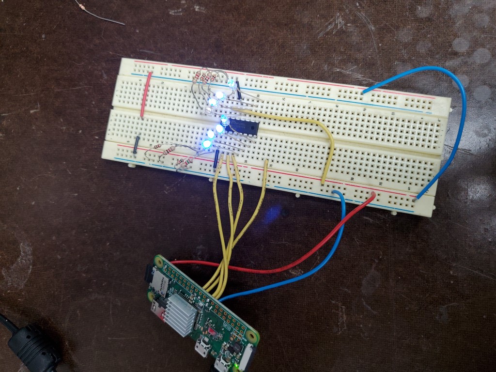
Once the MIC5891’s arrived I did a quick breadboard test with the PI powering a single shift register with some LEDs. In this test the MIC actually accepted the PI’s 3.3V signals, but I wouldn’t trust this to be reliable and will still include the level shifter on the full board.
To finish the design I added a few FET switches which will allow me to eventually route spare outputs on the Pi through this board to a satellite board that will control the vacuum pump (On/Off/Speed). I also added a 12V to 5V DC-DC power supply so that I can bring a single 12V supply into the control board and have it power everything, including 5V back out to the Pi. This was all drawn up in CircuitMaker.
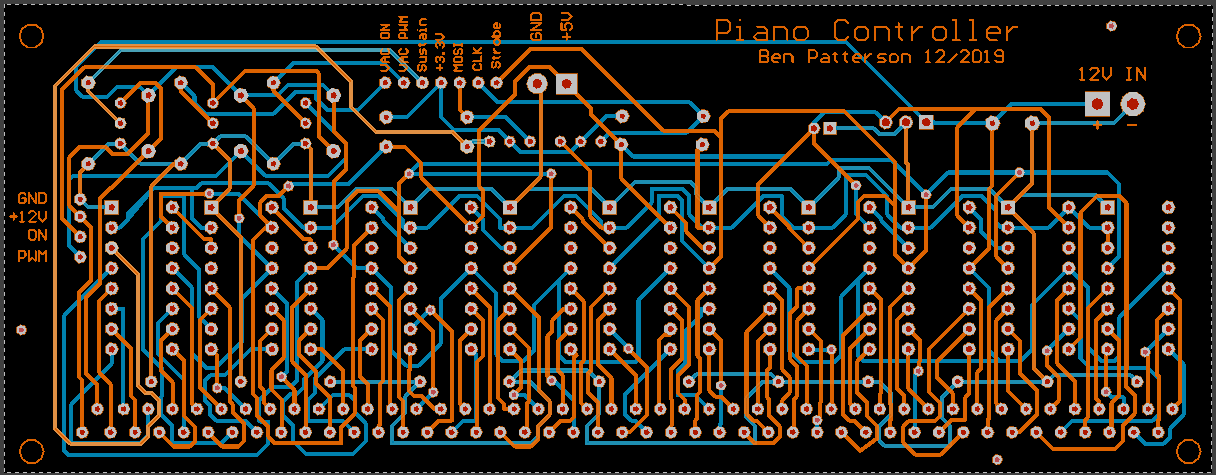
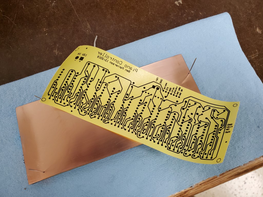
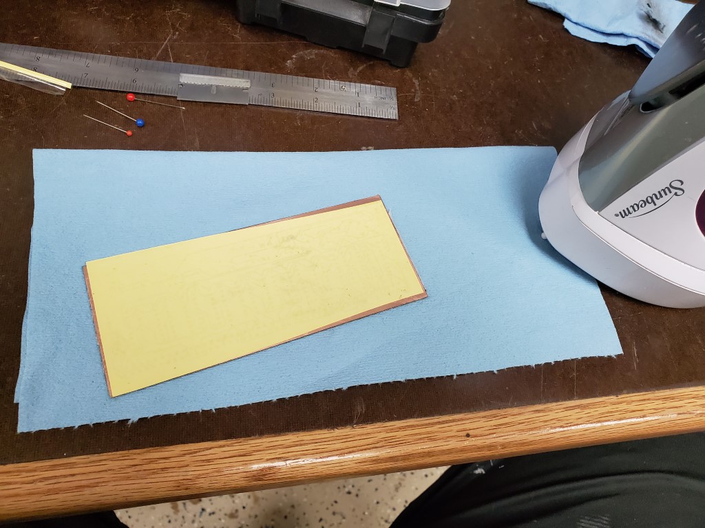
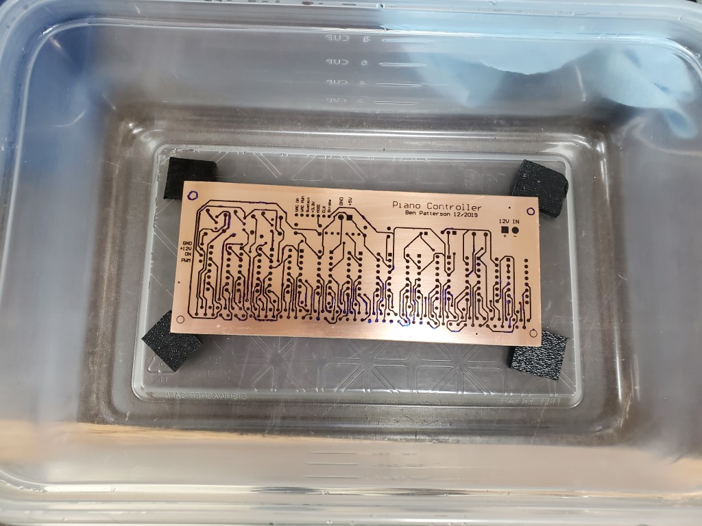
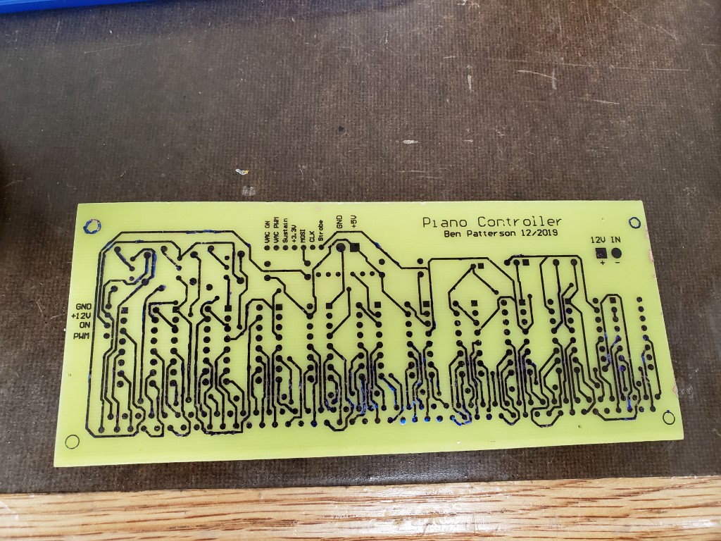
Creating the actual board consisted of printing the circuit design onto toner transfer paper, with scaling 1:1 and with the top layer mirror-imaged. I cut the board blank to size and drilled small holes that I had added to the design as alignment points. The board was then cleaned carefully with fine steel wool and denatured alcohol and then I ironed the transfer paper onto the board. When the board had mostly cooled I pulled off the transfer paper revealing the design. In the past I had used photo paper for transferring toner; this was my first time using purpose-made toner transfer paper and it definitely was much better – the board only required minor touch-up with a fine tip marker prior to etching. After etching in Ferric Chloride, steel wool and denatured alcohol were used to clean the toner/marker from the board.

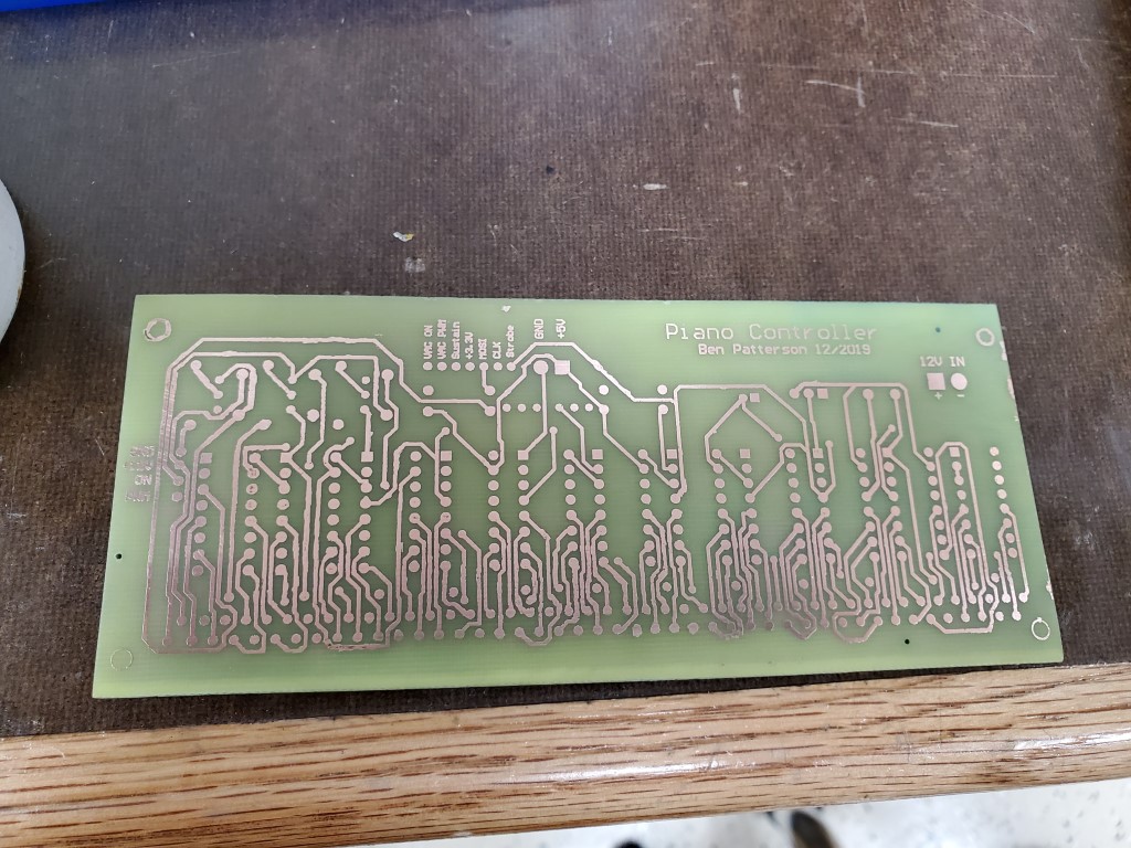
The next steps are to drill all the pin holes and to fully tin the board to increase the ampacity of the traces and prevent corrosion, I’ll do this prior to populating and testing the board.
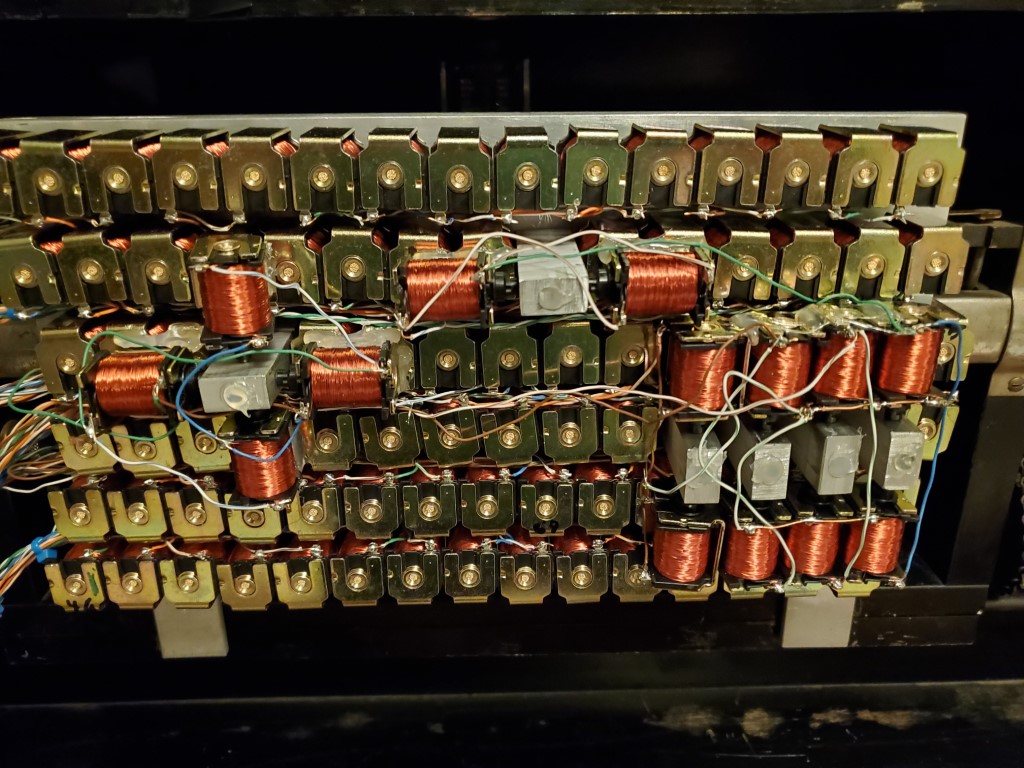
Piano Automation – Valve Manifold Complete
This weekend I had a chance to test the completed valve bank.
Testing revealed that some of the keys did not actuate with their corresponding valve open. On these keys when the valve (while turned ON/open) was removed from the manifold the key would strike immediately, pointing to lack of airflow through the valve as the cause. I can’t explain why this occurs on only some of the keys but the piano turns 100yrs old next year, so the inconsistency isn’t surprising. The piano could perhaps be adjusted to make these keys work the same as the rest, but I could more easily just provide more airflow via multiple valves per key – this is the approach I took. To connect multiple valves per key I created a few hollow standoffs that fit inside the valve holes in the manifold . The standoffs then have holes on their sides to allow connecting the extra valves on a 2nd layer above the rest. The end of the hole that was drilled to hollow the standoff was sealed with hot glue. Two valves solved the problem for most of the offending keys, but one extra special key required 4(!) valves in a ‘+’ configuration.

With the mechanical parts complete I’ve taken the first steps to construction of a raspberry-pi based controller that will use shift registers to power the solenoids. The raspberry pi and associated circuitry will be small enough to fit on the back of the valve manifold in the area where the paper roll would normally be. It has wireless connectivity and I plan to have it host a webpage where it can be controlled by phone/tablet. I’m bread boarding this first to prove the concept with one shift register, then once testing is complete I’ll create a circuit board to hold all 11.
Piano Automation Continued
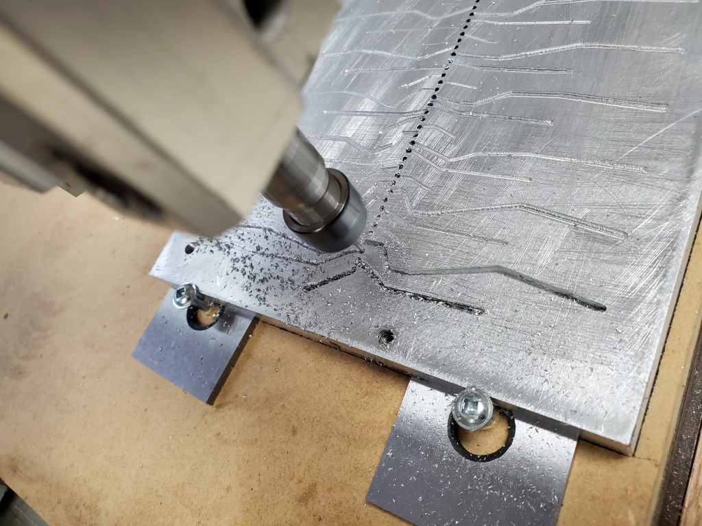
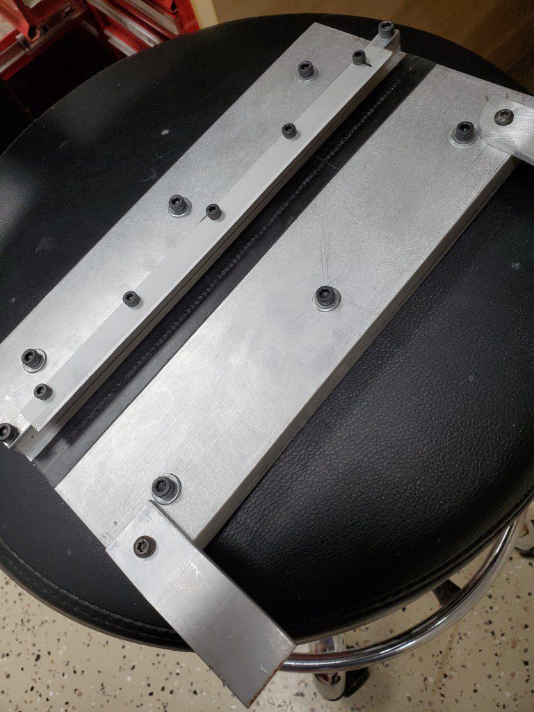
Over the past week I finished the lower valve manifold plate. The lower plate connects the row of holes on the piano tracker bar to the valves on the top plate. Obviously it would have been nice to just put the valves directly over each hole, but since the valves are much wider than the hole pitch I had to instead design the manifold with the valves arranged in multiple rows. Each tracker bar hole is connected to the valve above via passages that are routed into the bottom plate. The path of each passage was chosen carefully to avoid connecting to other valves/passages and to avoid running into the bolt holes that connect the manifold halves – each valve should connect to exactly one tracker bar hole. I let the CNC router do this work; it was relatively slow going with a 1.5mm end mill in aluminum but it turned out OK.
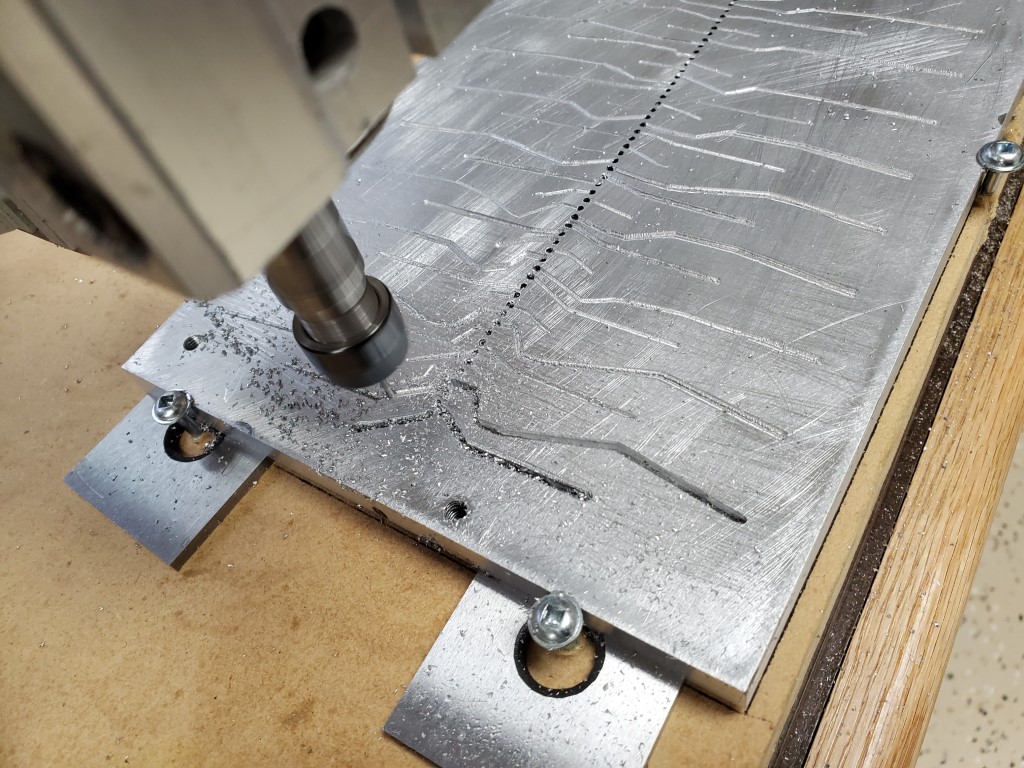
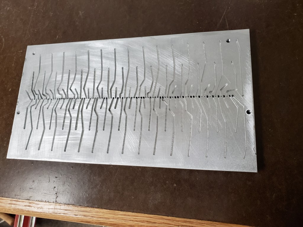
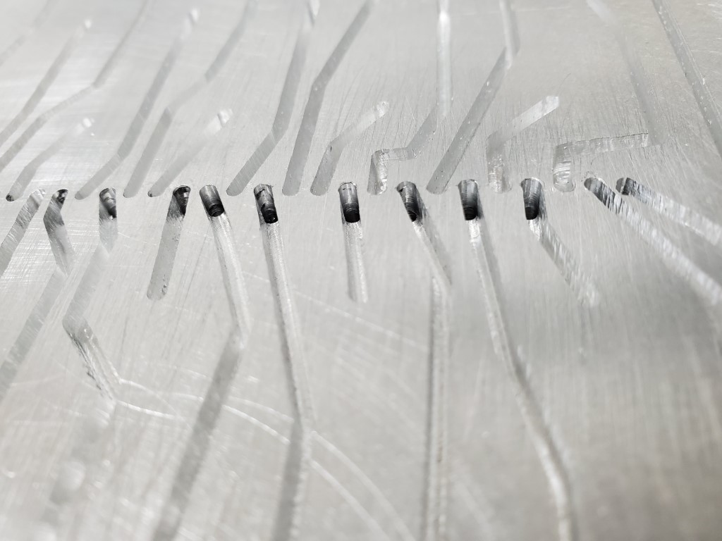
After the passages were milled I created a gasket using wide tape. The tape covers and seals the top of the passages and a hole punched at each valve location allows each valve to connect to its passage. The tape has enough compression that any imperfections in the plates will be sealed once the plates are bolted together. I also added a lip/shelf to the back of the manifold to hold it in vertical alignment against the tracker bar.
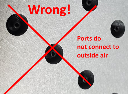
With the manifold ready, I connected it to the piano and tried firing the outputs. Results were not good, there was some vague correlation between outputs being on and notes being played but something was wrong. I had originally assumed the air passed all the way through the valves but closer examination revealed that they actually pass air from their stem to ports near the base of the stem. Since I had the entire stem/base of the valve mounted inside the manifold there was nowhere for air to flow when the valve opened. I re-made the top plate with smaller holes and re-installed the valves with only the stem in the manifold.

Remaking the top plate solved the valve problem but there were many dead notes due to air leaks at the tracker bar. I experimented with several materials to seal the tracker bar to the manifold and ultimately landed on thick rubber outdoor electrical tape as the best performing, though many leaks remained. I found that the tracker bar was not very flat and I was able to carefully bend it back. This helped considerably but leaks still remained. I found that the force needed to push the manifold against the tracker bar for a good seal had the effect of bowing the tracker bar away from the manifold in the middle, so I added a thin aluminum lip to the shelf on the back of the manifold. The lip is just thin enough to fit between the tracker bar and the wood cover behind it and it allows the manifold to hook over the top of the tracker bar and more positively hold the bar along the entire length of the manifold with enough preload on the tape to seal. This essentially solved the leak problem.
Currently there are ~12-15 keys that I’m tracking down problems with, this started from ~20 and was reduced by working through electrical/alignment problems. On the remaining dead keys I’ve ruled out problems on the piano side, problems with the lower plate, and any electrical problems; so next step may be replacing the valves themselves. It’s possible that those keys need more airflow, which would require milling their passages deeper and/or modifying the valves; hopefully it doesn’t come to that. Once they’re all firing though then the mechanical work on this is basically done and I’ll be able to shift focus to the control system side.
Piano Automation Begins
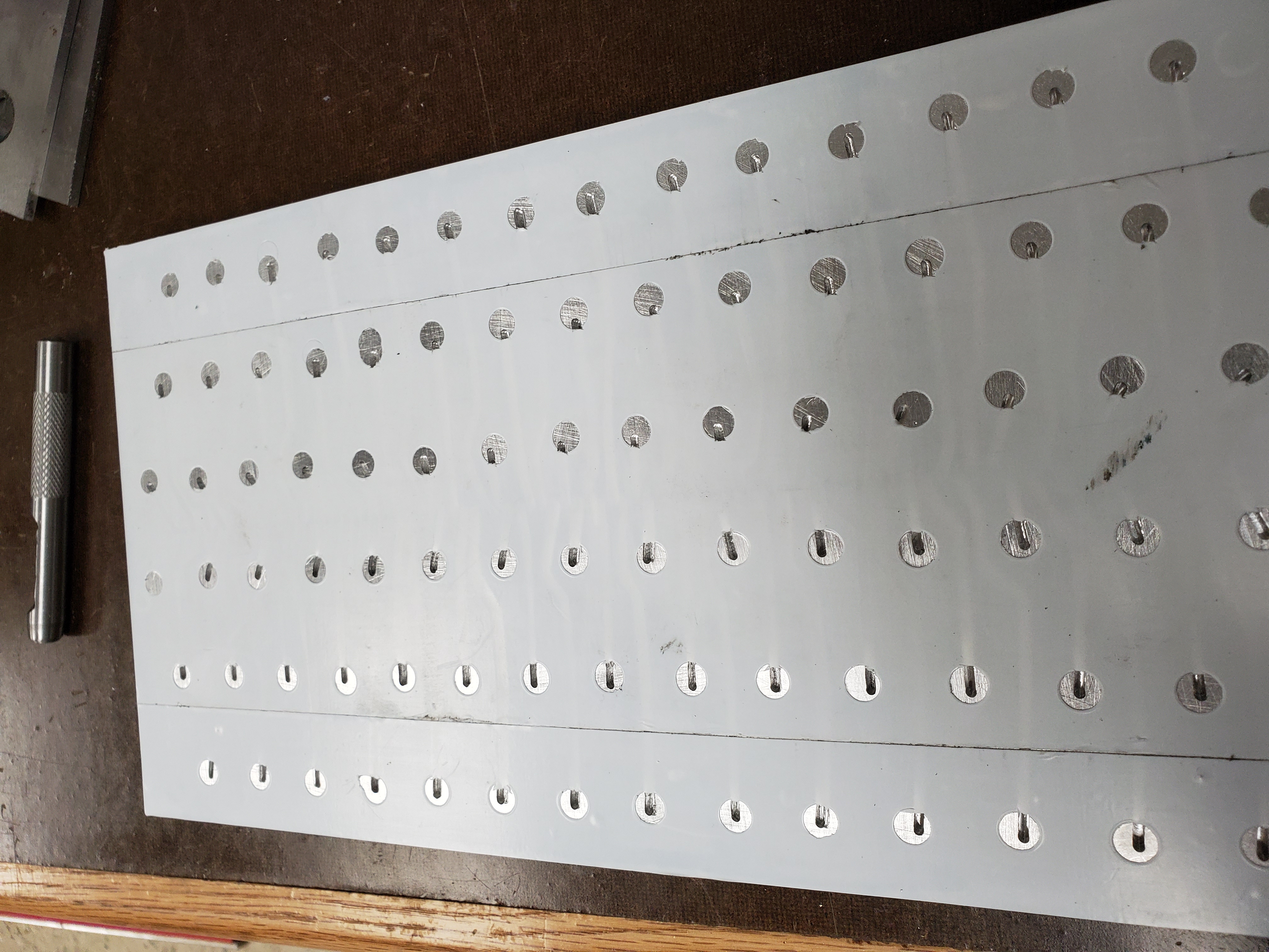
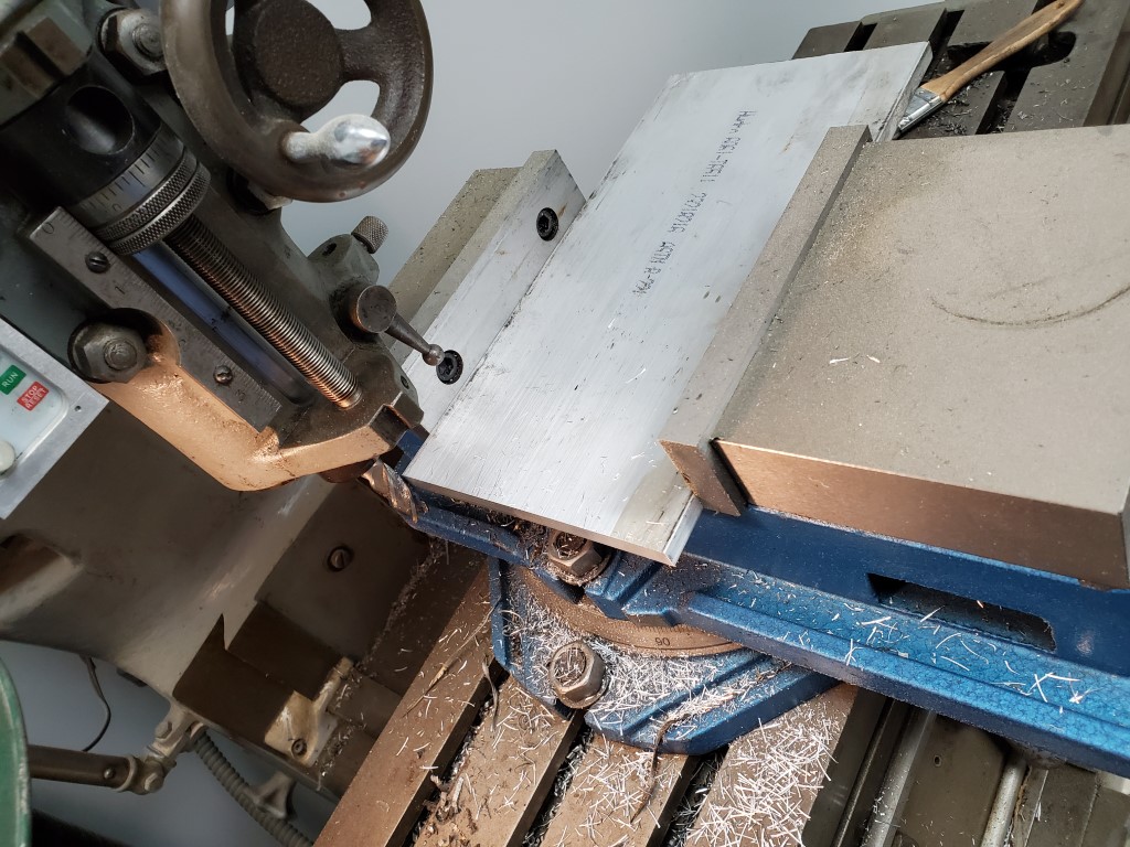
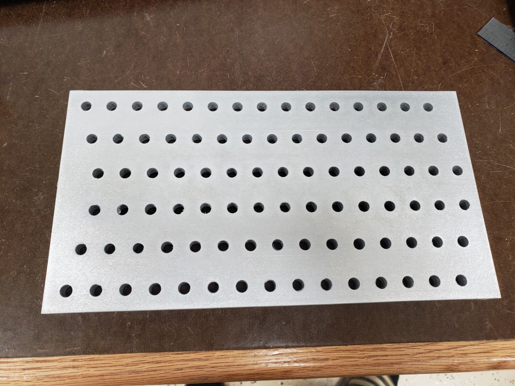
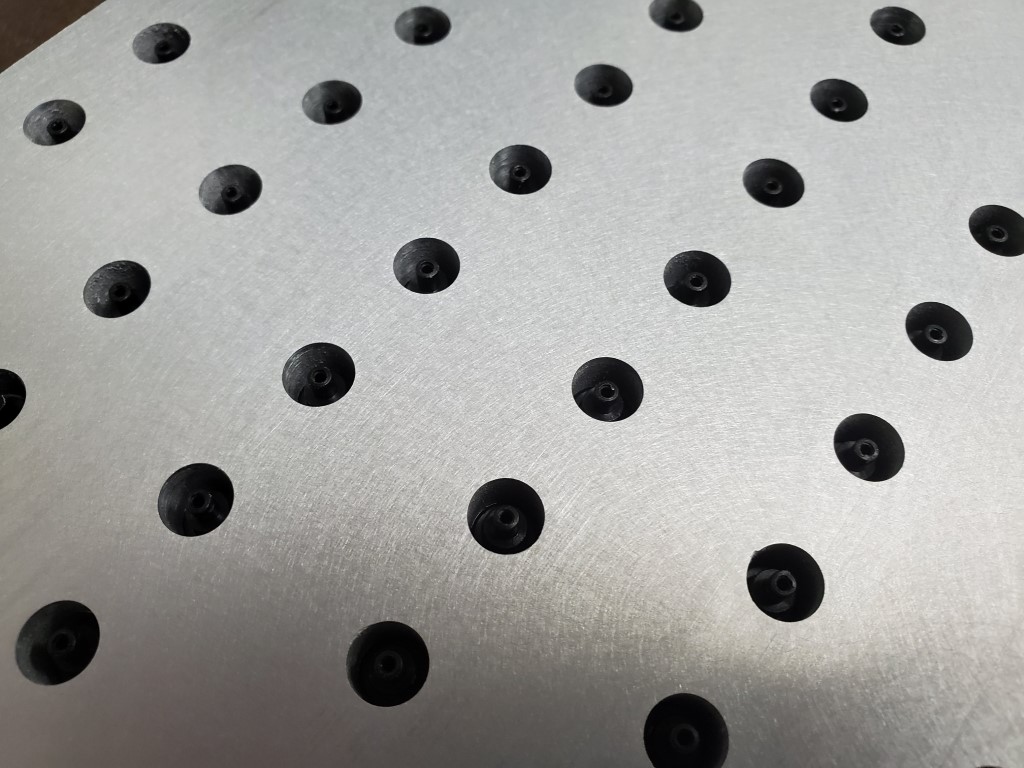
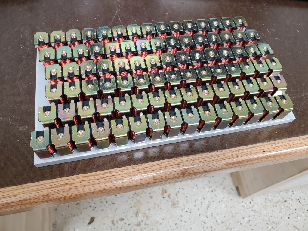
This weekend I designed and began fabrication of the parts needed for adapting the solenoid valves to the piano’s tracker bar. This adapter will consist of two 3/8″ aluminum plates. The top plate will have holes to accept the solenoid valves, and the bottom plate will have holes to interface with the piano’s tracker bar. Grooves will be machined into the bottom plate to create airs channel between the tracker bar holes and the solenoid valves above. The two plate will then be sealed together, covering the grooves; a similar construction technique as some carburetors. As long as the grooves are carefully routed, each valve should connect to exactly 1 tracker bar hole.
I cut the 3/8″x6″ plate on the band saw and then milled to final length. I used an edge finder to locate the plate edges, and then used the mill’s digital readout to position above each row/hole. For each row I took 2 passes, first spot drilling with a center drill and then drilling to size with a twist drill. 88 * 2 plates * 2 passes = 352 cycles of positioning the X axis and drilling a hole. Once all the holes were drilled I sanded sides to remove burrs from the holes and scratches from the rough plate.
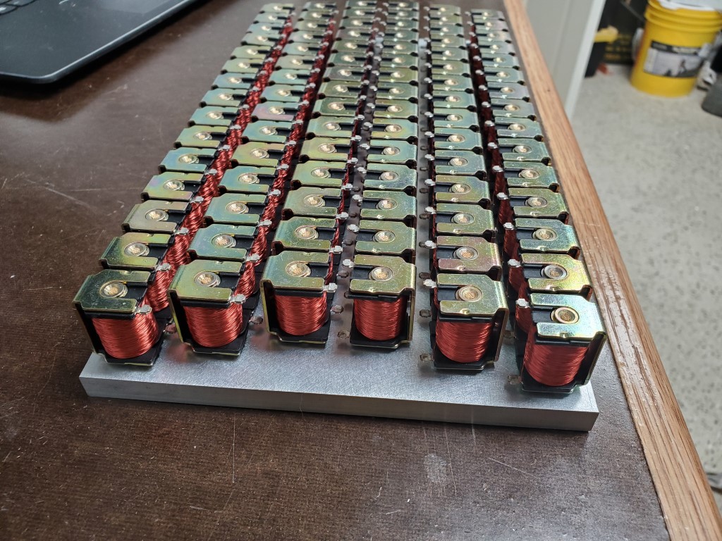
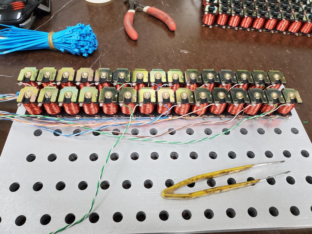
Next I installed and wired the solenoid valves in the top plate. The solenoid valves are an exact fit to the hole, but I added a bit of CA glue to ensure they stay in place. Wiring consists of scrap Ethernet cord that’s been stripped back; Every ~7 solenoids each share a common wire to reduce wiring, but it’s still ~100wires.
I’m happy with the results so far; this is by far the most precise thing I’ve made on the mill and everything is lining up perfectly. The next step will be to 3D model the grooves and convert these to paths to run on the CNC router. I’ve done some aluminum milling with it previously so it should work out OK, especially since it’s just cutting the shallow grooves – I wouldn’t have trusted the router to drill the holes as well as the mill did.


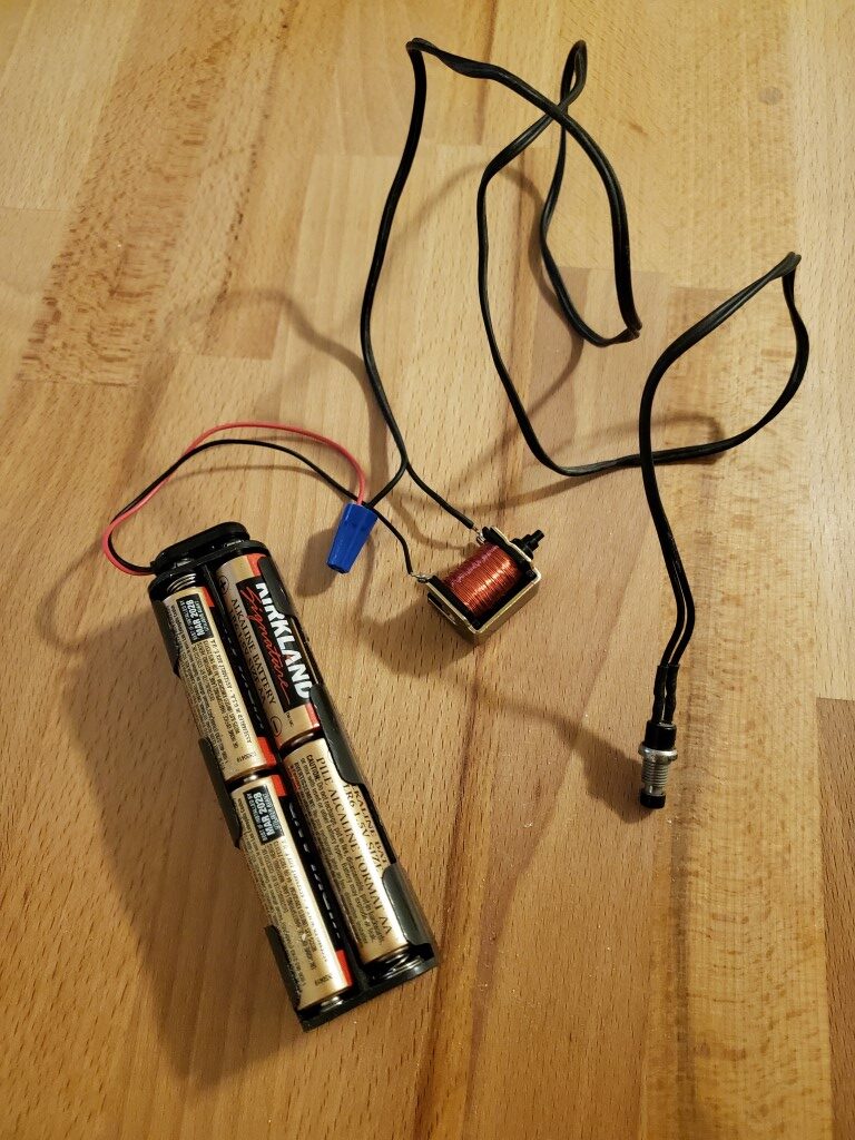
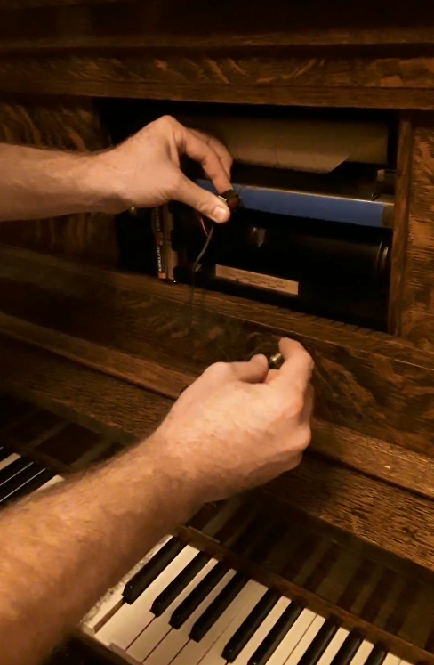
Piano Automation Proof-of-Concept
I did a quick test tonight to check/confirm the feasibility of using the ebay solenoid valves I got a while back to control the player piano. I connected one of the valves to a 12V battery pack and a push button, and then held it in front of one hole of the piano’s tracker bar while the rest were taped closed. When I pressed the button, the valve opened, and the piano played the key! With this successful test I can move forward with designing an adapter to connect all 88 valves to the tracker bar.