

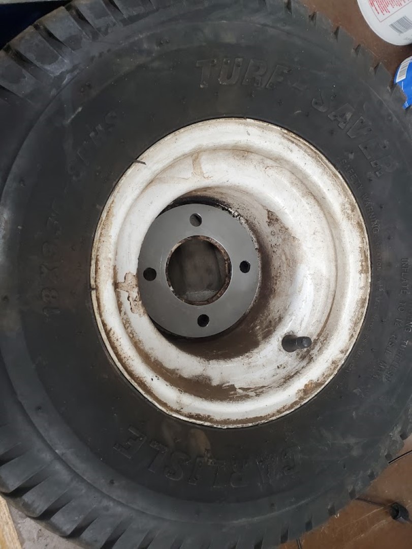
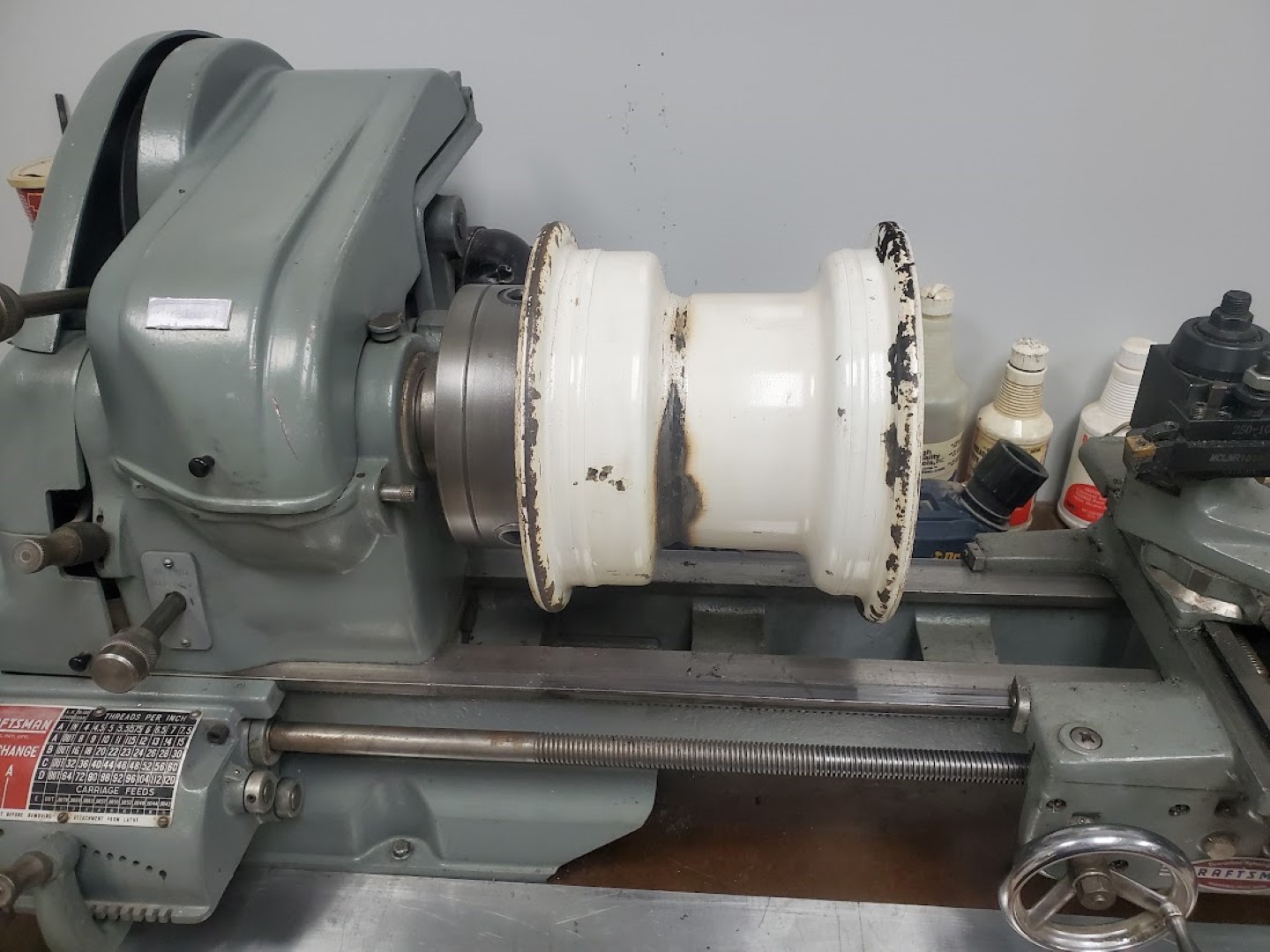
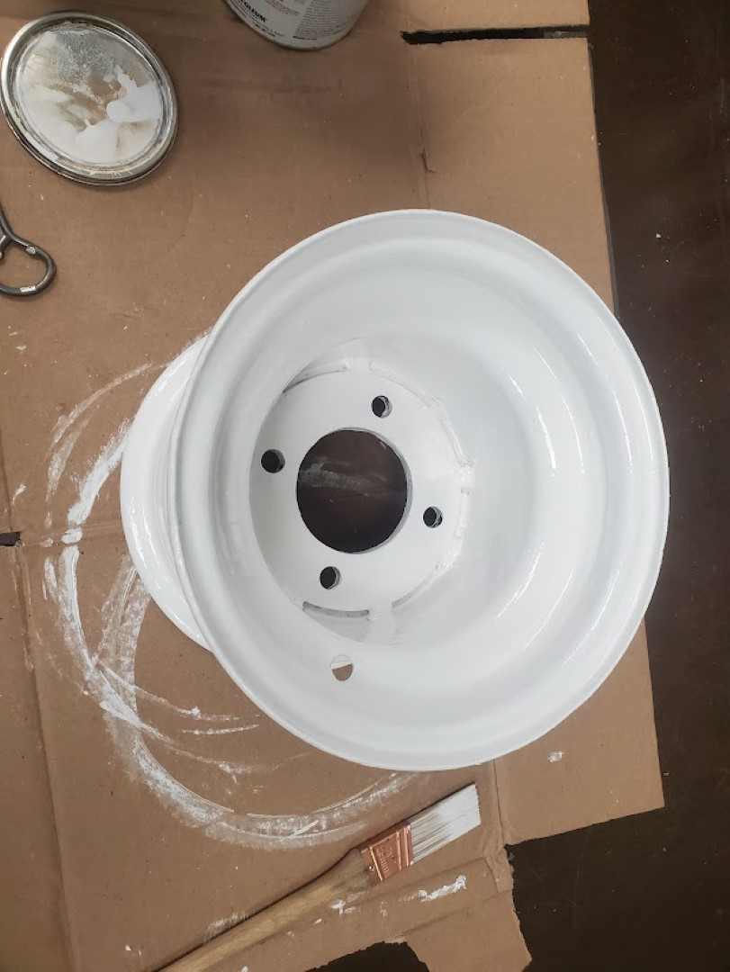
Kubota F2000 Wheel Rebuild
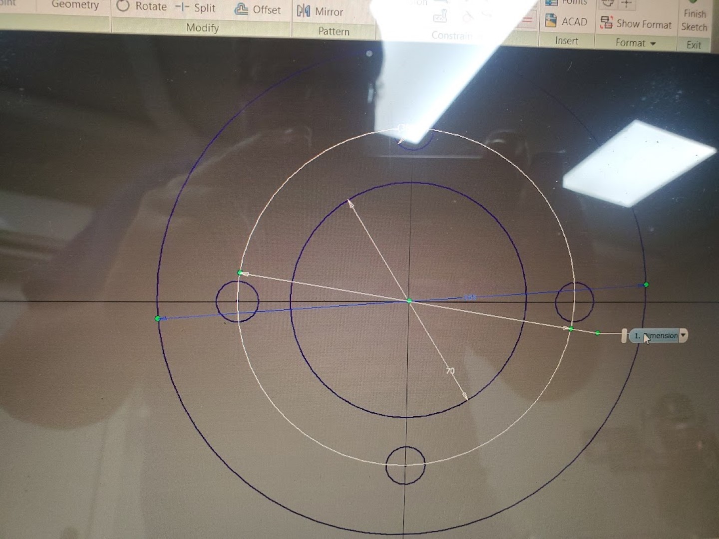
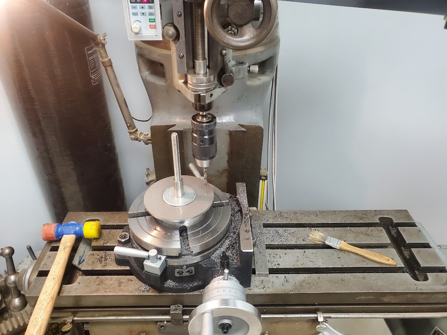
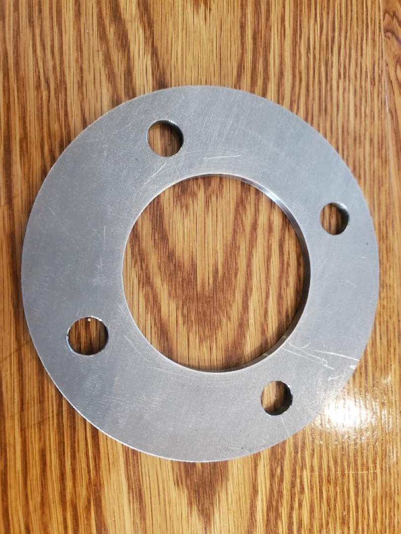
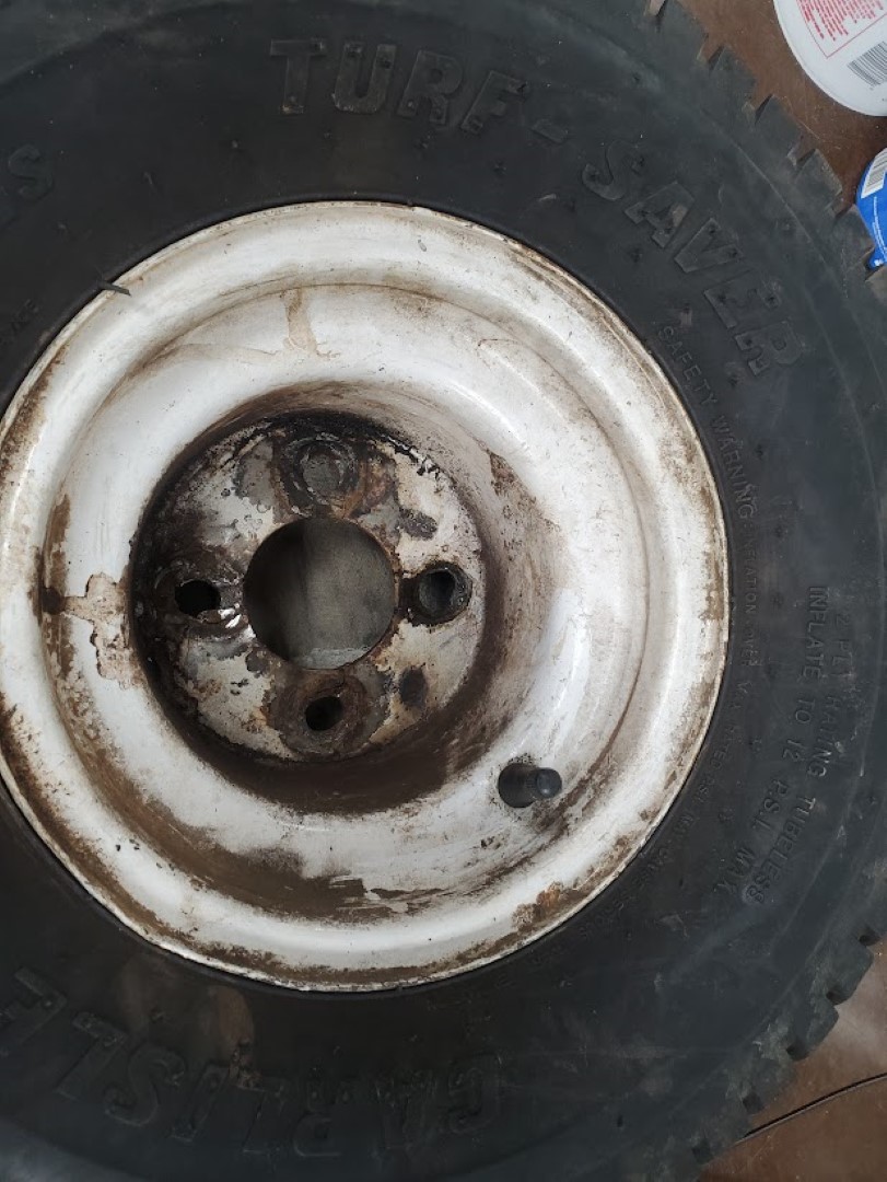
Recently one of the wheels on the mower broke. This hub of this particular wheel has always been a weak point and I’ve welded it back at least once. This time it was too far gone though and I intended to replace it… that is until I realized this wheel is a very odd size and offset that’s specific to this series of mowers. It wasn’t clear that replacements were obtainable. With that being the case I decided to machine a new flange that could be welded in place to reinforce the inner wheel. The flange consisted of a 1/4″ steel plate turned down to the right diameter, then center bored and hole pattern drilled on the rotary table. The flange was then welded in the wheel and the back side faced on the lathe to ensure the face of the wheel would be perpendicular to the axle hub.
Audi S4 3.0T Secondary Air Cleaning
Part 1: Background
A while ago my check engine light began coming on sporadically, after scanning I found this was related to P0491 & P0492 errors. These errors indicate that insufficient airflow is available to the secondary air system that’s responsible for getting the exhaust catalysts up to temperature quickly at start-up. These errors would self-clear, but over time the light stayed on longer until eventually it stayed on.
I first checked all the ‘easy’ stuff related to this fault: the secondary air pump and solenoid both worked OK via VCDS and no leaks were found on any of the tubing. I also tested the “combi” control valves which successfully blocked air flow when blowing through the secondary air pipe and allowed air when manually actuated with a vacuum pump. At this point I ran a good amount of seafoam and intake cleaner through the secondary air pipe that goes under the supercharger, using a HVLP paint blower to push it through the system while the combi valves were held open with vacuum – lots of smoke, no change.
This unfortunately left blockages in the cylinder head’s internal secondary air ‘manifold’ as a most likely cause for the problem, there’s a TSB with lots of good info here: https://static.nhtsa.gov/odi/tsbs/2018/MC-10153120-9999.pdf (Required Reading for this topic!)
Options at this point, in order of consideration, were:
#1 – Take it to the dealer for the 120k mi extended secondary air warranty, I had ~110k mi at that point. I strongly considered this, but in the end it didn’t seem worth the hassle. With it being high mileage by their standards I fully expected to get push-back or some excuse for it not to be covered, while potentially being on the hook for their ‘diagnostics’ fees. Either way this was likely to be a less enjoyable experience than wrenching in the garage over a long weekend.
#2 – Buy the VAS6825 tool and do it myself. The TSB has plenty of info to do the job successfully, OK let’s just order the tool and …….. it costs how much?!?!
#3 – Make the tool myself and do it myself. The tool is simple enough, and I was reasonably confident a usable tool could be made at home. I went with the last option, let’s make the tool….
Part 2: Tool Creation
From photos online, the official tool (fig. 1) appeared to just be two smallish diameter flexible pressure washer tubes: one that’s basically a tiny sewer jetter, spraying forward, and the other that sprays out sideways. The main passage can be cleaned manually (coat hanger, vacuum), so only the sideways spraying tool is needed. The sideways spraying tool also comes with two plates, a bushing, and an attached scale to correctly position jet in front of the perpendicular passages while still allowing some movement for wiggling the jet around for better cleaning. For my purposes the whole bushing, plate, and scale arrangement would also be omitted – I’d be using a camera to locate the distance to the passages and then positioning the tool manually. There’d be no damage risk from a misaligned jet, as water doesn’t cut aluminum at 4000psi, so the water would just come squirting back out around the tool. I assume the official tool only has the extra complexity to justify its exorbitant price and to make it more suitable for use in a professional environment.
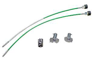
Figure 1: Official VAS6825 tool
With that settled, I only needed a long tube with a right angle nozzle. The small diameter pressure washer hose they use for this isn’t commonly available and even if it were its not clear that any fittings would fit inside the passage. (They use a crimp connection to get around this, but that’d require expensive crimp tooling in the strange tubing size – big money for something that I’d likely never use again). The good news is that the main secondary air passage is perfectly straight, so there’s no reason for flexibility at all. With this in mind the plan quickly coalesced around using some steel tubing. The tubing I selected was a 3ft length of 3/8″OD with 0.083″ wall thickness (McMaster 89955K459). This thickness is massively overkill vs the 4000PSI of my pressure washer, but a big ID isn’t needed for flow and I was more concerned with having enough metal thickness to get good welds.
From there I took a spare chunk of 1/2″ round bar, bored a 3/8″ hole to accept the tubing, and tapped the other side to 1/4″NPT for the pressure washer coupler. (fig. 2) I did this on a lathe, but it could be done with a drill press or drill/vice if centered carefully. This was then welded* to the tube on one side along with a simple plug on the other.(fig. 3) At that point I had a fully sealed tube to which I drilled an ~0.043″ hole on the side of the end, giving me the right angle jet. (fig. 4) The hole size depends on the specs of the pressure washer, check tables online, 0.043″ was right for 4000PSI / 3.5GPM. The official tool appears to have 3 holes – I suppose you could calculate the right hole sizes for this and do it that way, but the single hole is already tiny and any performance loss from this is easily overcome by wiggling the single jet around more/longer. Lastly, add a line along the tool so it’s clear which way the nozzle is pointing. Total cost less than $30.
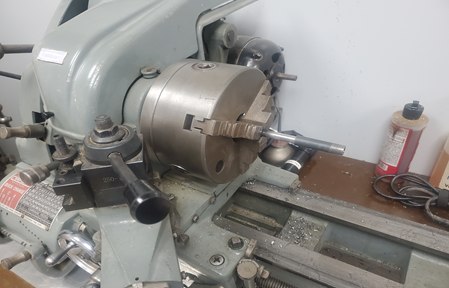
Figure 2: Making the end adapter
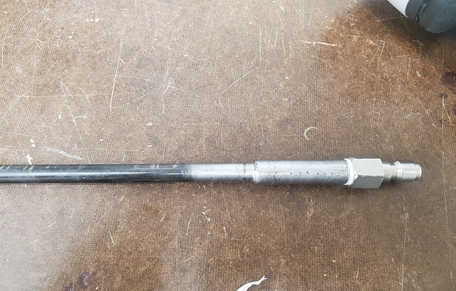
Figure 3: End adapter welded to tube, coupler fitting attached
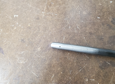
Figure 4:Nozzle Orifice Drilled
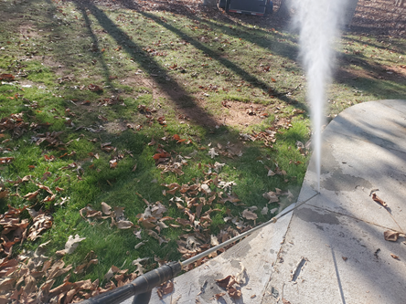
Figure 5 : Testing
*Warning: This is effectively a DIY hydraulic line under a few thousand pounds of pressure. It can
fail forcefully with risk of injury.
Part 3: Cleaning
As always, remove the entire front of the car using whatever method/sequence you prefer. You’ll need unobstructed access to the front of the engine. I was able to suspend the bumper/radiator support from the ceiling and hinge it open like a gate to avoid disconnecting the AC lines. Note though that this puts strain on the upper radiator hose and that will crack the coolant crossover pipe, so disconnect it first. I only left the hose connected because I couldn’t get it off the pipe without destroying it, so it was probably doomed either way.
Get access to the secondary air ‘manifold’ freeze plugs (fig. 6); there are a number of things in the way (belts, coolant flange, hoses, etc) but if you’ve gotten this far you’ll figure it out. Pop one side of the freeze plug with a drift punch and it’ll rotate so you can yank it out with needle nose pliers. Remove coils and plugs at this point also.
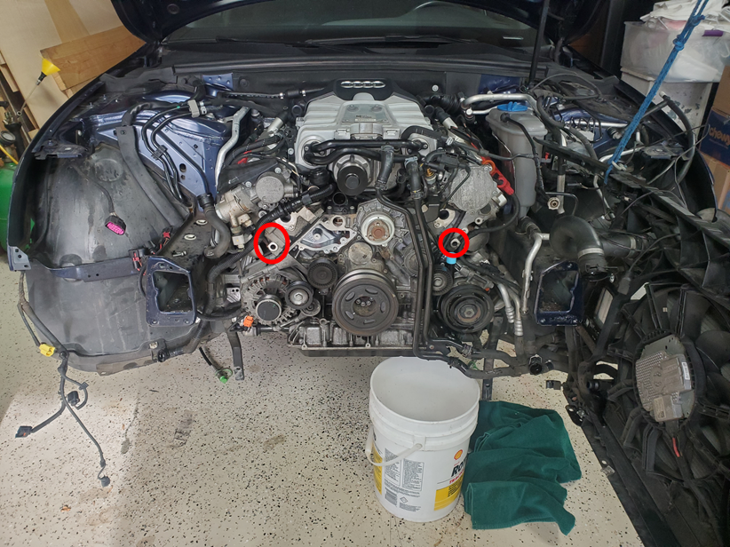
Figure 6: Secondary Air Passages from the front of engine
Next use the right angle camera mirror to find the air passages with the angle of the exhaust manifold flange for reference. The passages are drilled straight from the flange (where they dead-end) up to the back of the exhaust valves. Point the mirror up in that direction, it’s the part of the passage that goes up into the valve that we want to clear, the other part that dead ends onto the back of the exhaust flange is only there because it’s much easier for them to manufacture the head that way. Once the passage is centered in the field of view mark the camera cord where it enters the cylinder head, I used colored electrical tape with different colors for each bank; repeat for all 6 passages. (fig. 7) Reference measurements in table 1.
| Driver (US) | Passenger | |
| Front | 75mm | 45mm |
| Middle | 165mm | 135mm |
| Rear | 255mm | 225mm |
Table 1: Distance from Port Edge to Passage Center
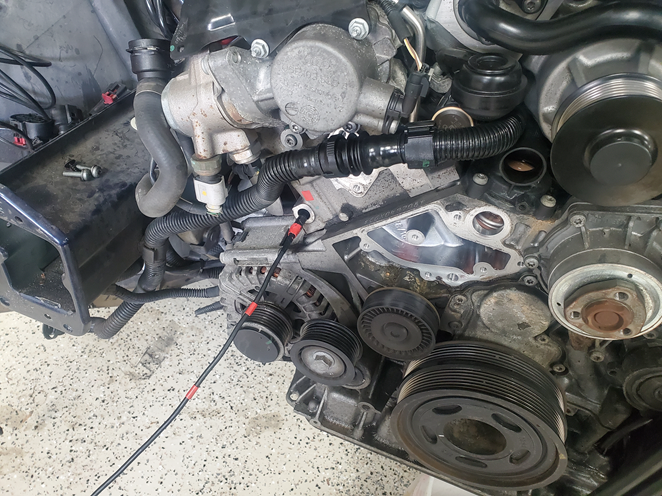
Figure 7: Marking the individual passage locations
Warning: Make sure the camera body is securely attached to the cord! Even though my camera (depstech) appeared to be one piece it decided to separate – the cord pulled out and left the camera guts and front body in the passage. This could be disastrous as you’d then need to drop the transmission to pull off the combi valve to push the camera body out from the other side. I was extremely lucky this happened close enough to the end that I was able to access it with small needle nose pliers and pull it out. It re-assembled no problem, the cord had a connector inside the camera body. After that I epoxied the cord to the camera body and wrapped them together with electrical tape for extra insurance.
Next put the camera and cleaning tool next to each other with the mirror and nozzle orifice aligned and transfer all the markings onto the cleaning tool.(fig. 8) All that’s left at this point is to drop the exhaust before the catalysts, setup a big storage container to catch the water, insert the tool, and start blasting. (fig. 9) You’ll also want a catch container up front under the tool, drape a wet rag (if it’s dry it’ll blow away) over the tool so that the water coming out will hit it and drop into the catch container. Insert the tool to the depth of the first marking and rotate so the line on the tool is facing the right way (the same angle you found the passage with the mirror). Set a timer for 3min and pull the trigger. You’ll get an initial blast of dirty water from the main passage as the jet eats through the blockage, this should pass almost instantly. If it doesn’t, you’re off-target – try rotating and moving the tool in/out until water stops blasting out of the front. It’s very apparent when you’re on-target, no water comes out of the front and there’s a satisfying gurgling noise. For the remainder of the time I just moved the tool in/out and rotated back/forth, changing direction when water began coming from the front. Repeat for all passages.
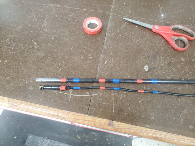
Figure 8: Transferring passage depths to cleaning tool
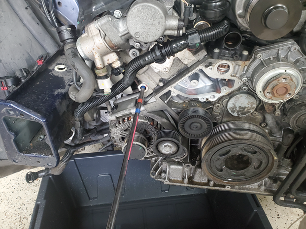
Figure 9: Blasting! (not shown aligned)
Once complete, use a vacuum extractor to try to pull water from all the plug holes. It was clear during blasting that one exhaust valve was open on each bank, and these two cylinders did have a little bit of water. Next crank it a few times with the plugs out as a precaution before fully reassembling and clearing all the codes.
The camera had a hard time focusing on the clogged ports, I had to really work to get usable pictures but you can see a very small dark area in the middle of the before shots – I believe these were the only open area and you can definitely see the edge of the port, so everything in-between was crud. (fig. 10) After cleaning I got great pictures with no effort at all that immediately showed fully clear. (fig. 11) The process was a success and the code has not returned as of many months later.
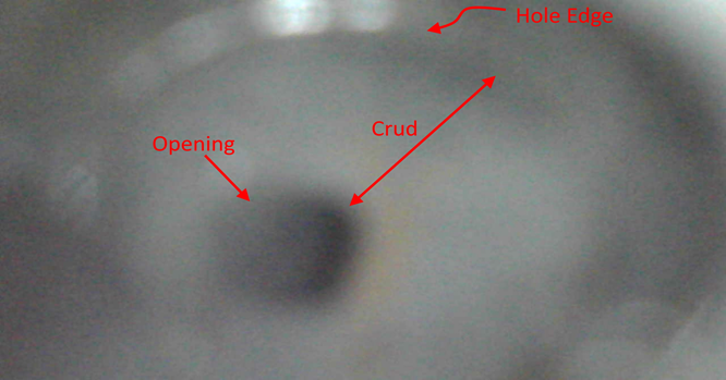
Figure 10: Typical Passage Before Cleaning
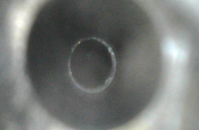
Figure 11: Typical Passage After Cleaning
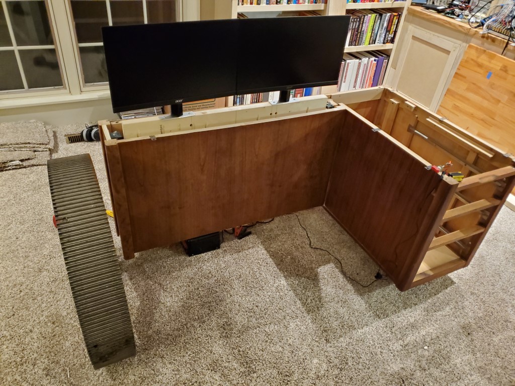
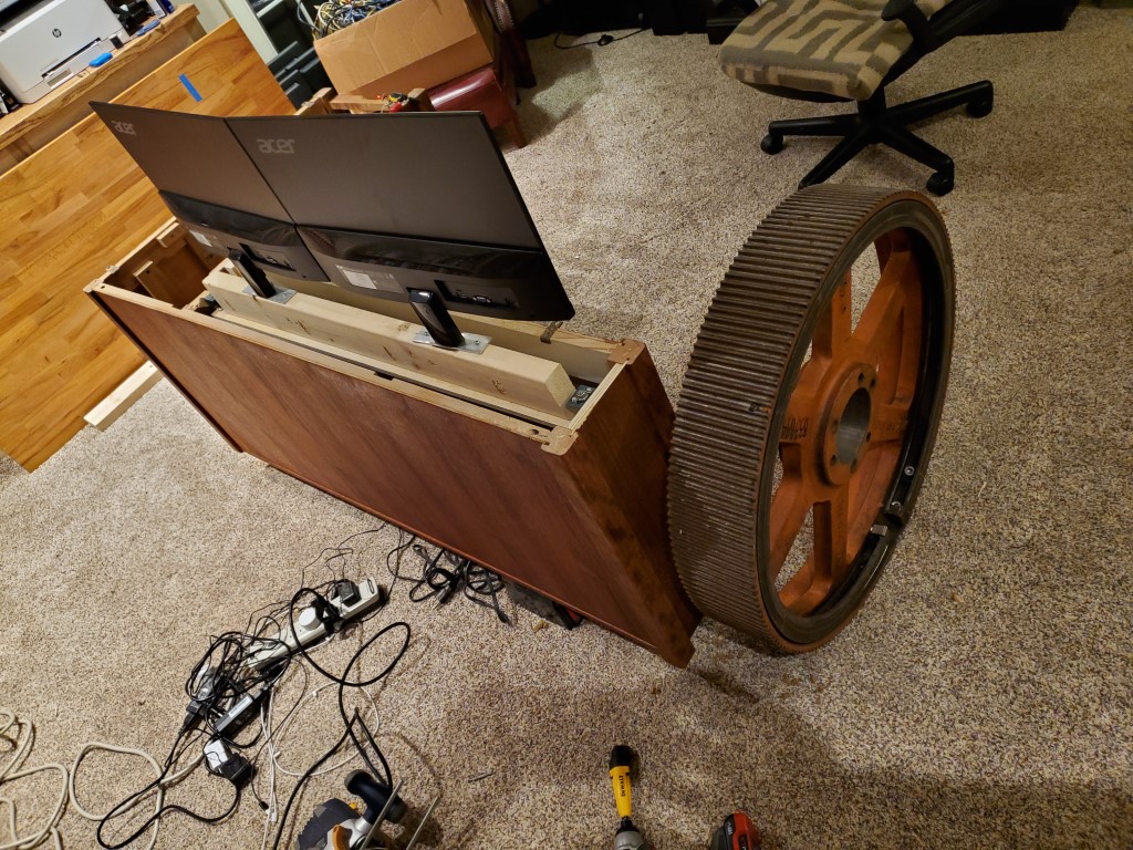
Custom Desk – Monitor Lift Mechanism
I got the idea for the monitor lift from an example online using all-thread as lead screws to drive a platform. Essentially I’m just replicating this idea but with a few tweaks that take advantage of having the lathe to make it better/stronger, easier to build, and to take advantage of spare parts I already had.
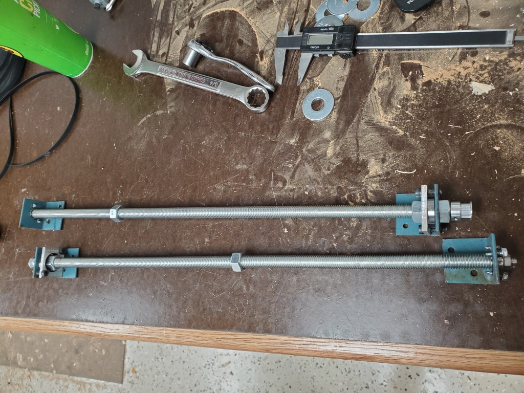
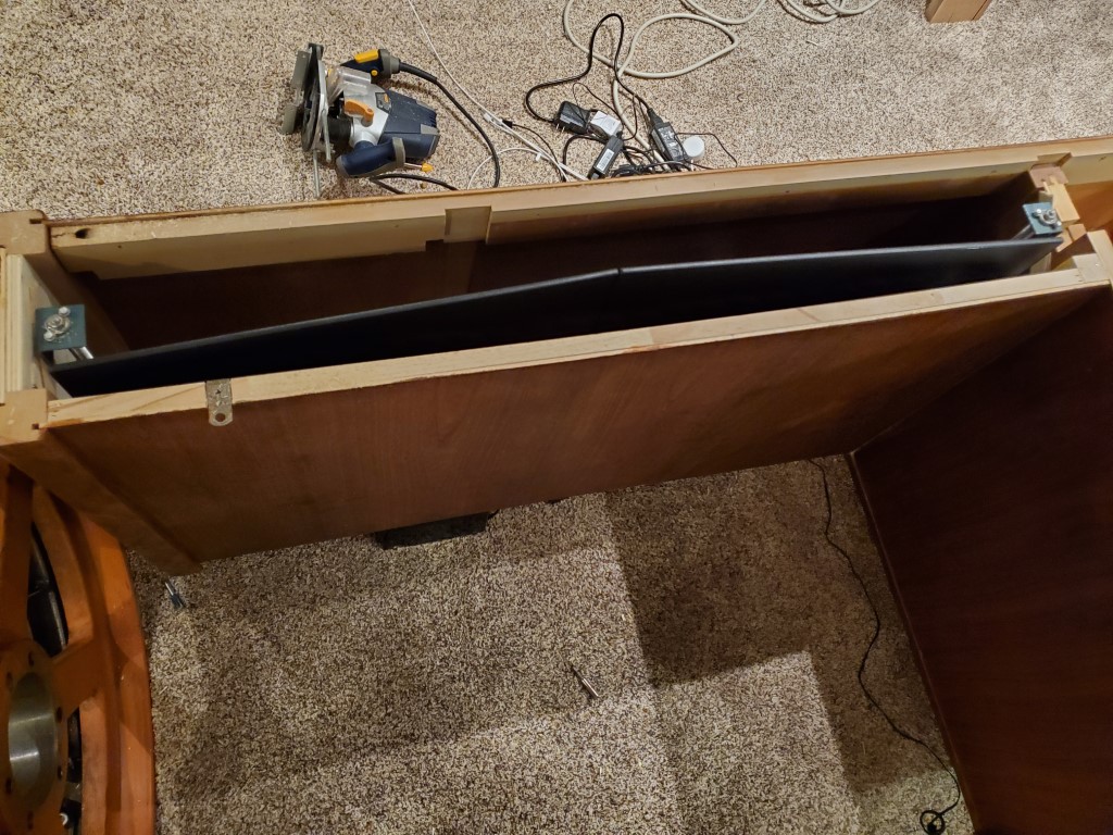
First I cut the all-thread rod to length and then I turned down one end of each to fit the inside diameter of some spare bearings. I left an extra bit on the end and turned it down to fit the inside diameter of a timing belt drive sprocket – this was later replaced with a chain sprocket due to slipping. I repeated the same on the top side of each rod (without the extra bit for the drive sprocket) and then I cut some metal brackets to hold the outer bearings. I then cut a small platform and attached two nuts to it that would connect it to the threaded rods.

These parts were all assembled into the desk; a few small shims were needed to get the rods exactly parallel. I then connected the threaded rods together with a small #25 chain drive. To power the lift I tried a few different test motors and eventually settled on the guts from a small/cheap electric screwdriver – this provided enough torque while not requiring a huge power supply. It could be a bit faster and I need to add some sound damping, but it’s working very well for an initial attempt.

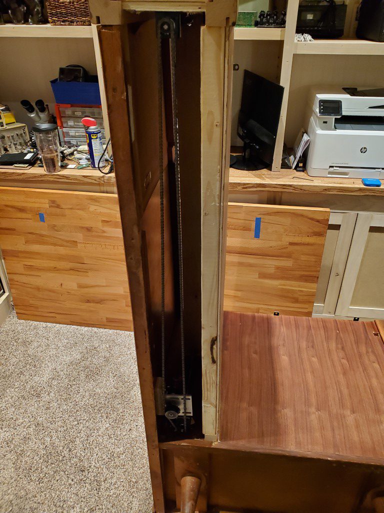
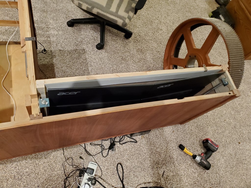
I also made some mounting plates to adapt the monitors to a fixed mounting since the regular bases were too wide. The monitors were then mounted to a 2×4 that acts as a spacer and also adds strength to the platform. Once the tabletop is in place the 2×4 and the rest of the mechanism will not be visible since the monitors will rise so that their bases are just flush with the top – I’ll likely add a trim piece to block this off. The monitors also drop low enough that the table top will clear with no problems.
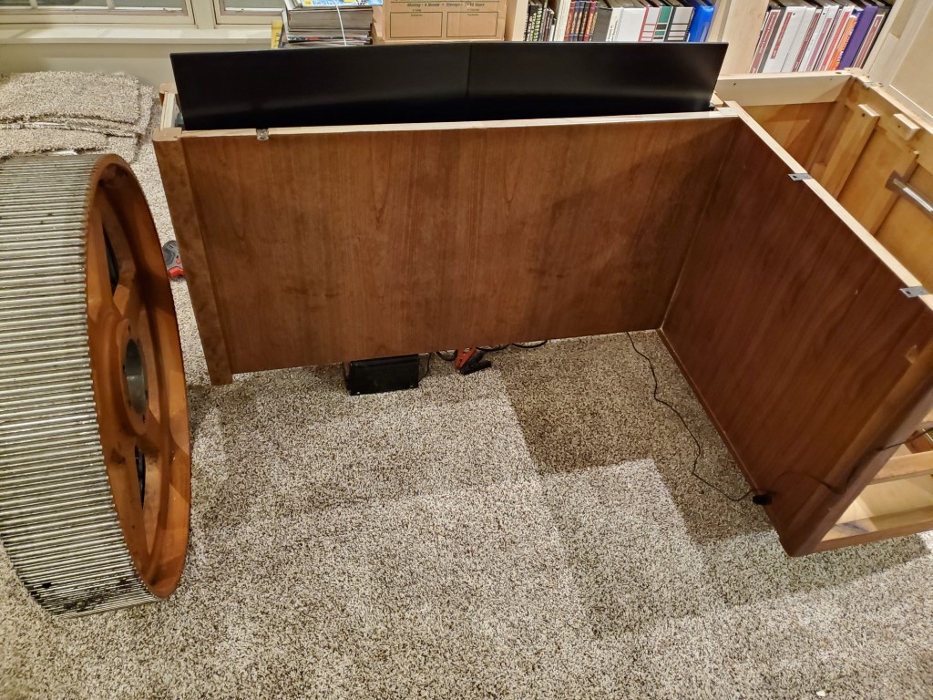
The last step was adding limit switches and rewiring – moving the toggle switch up runs the lift up until the positive switch is tripped, and moving the switch down runs the lift down until the lower limit switch is tripped.
Next up will be making the tabletop…
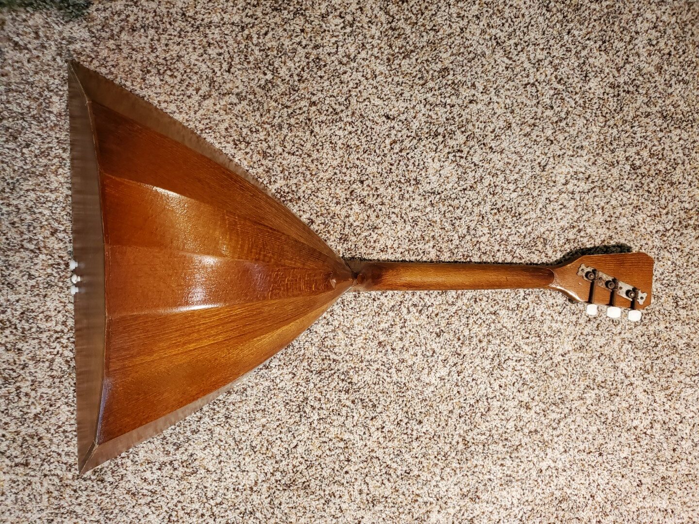
Balalaika Repair
It had been in storage and a few parts were missing that needed to be replaced:
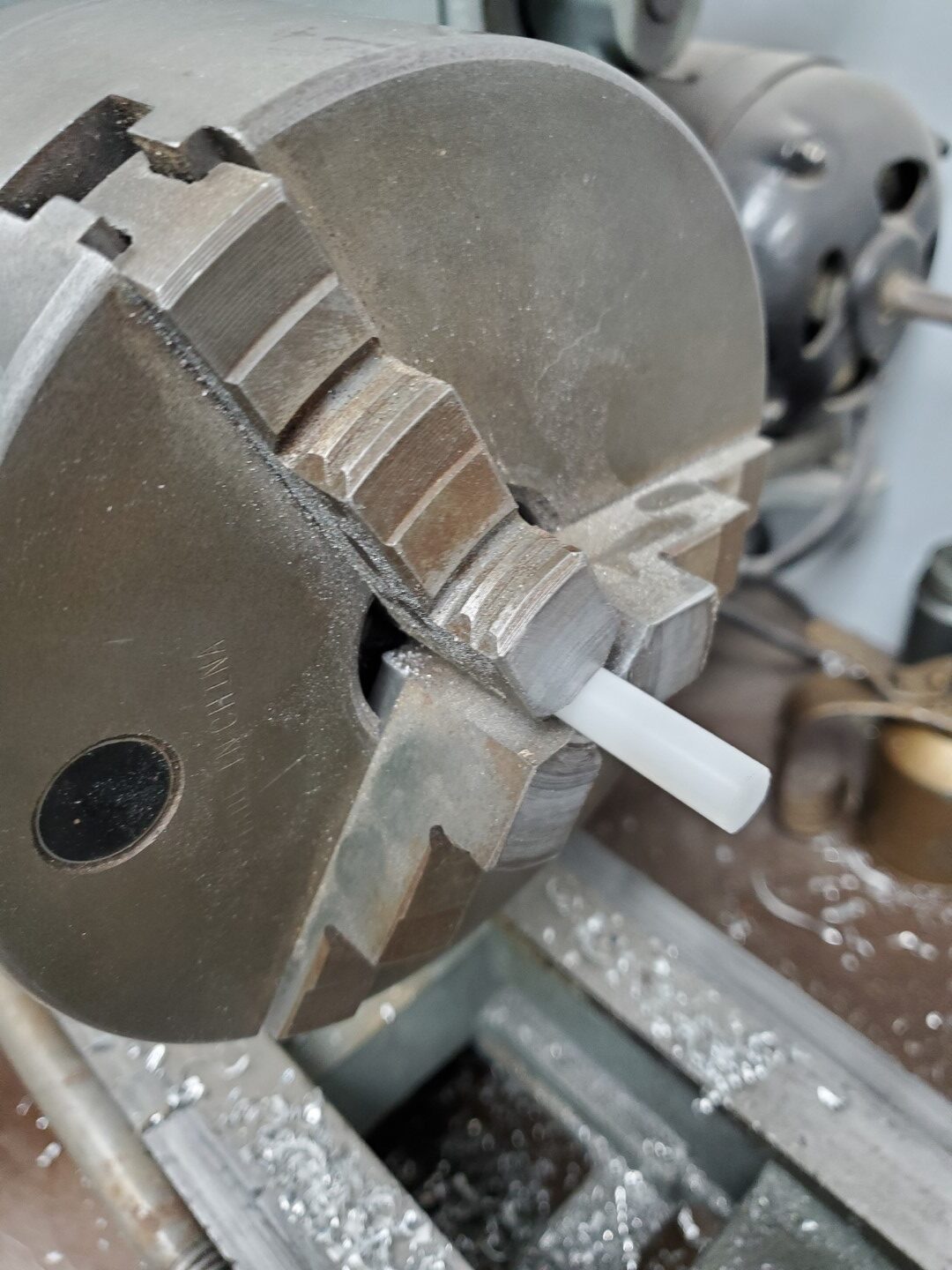
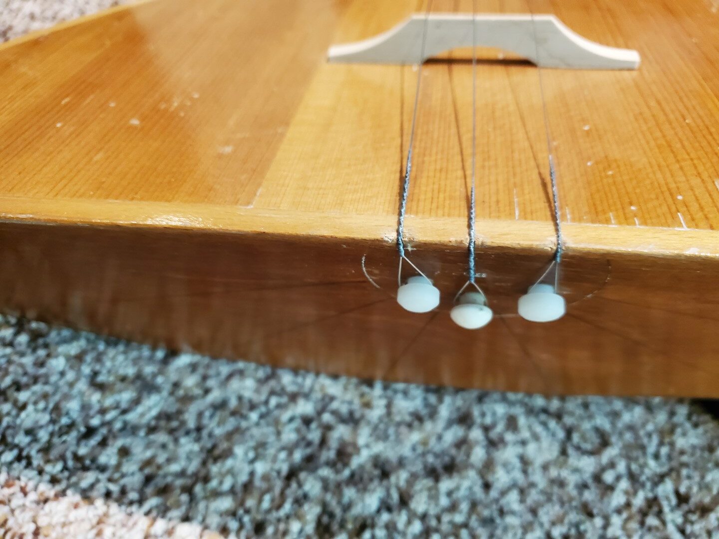
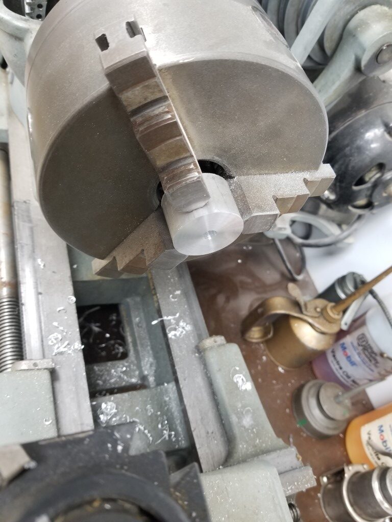
– End Pins – 1 of the 3 end pins remained and I used it as a reference for turning 2 more matching pins on the lathe from a plastic rod.


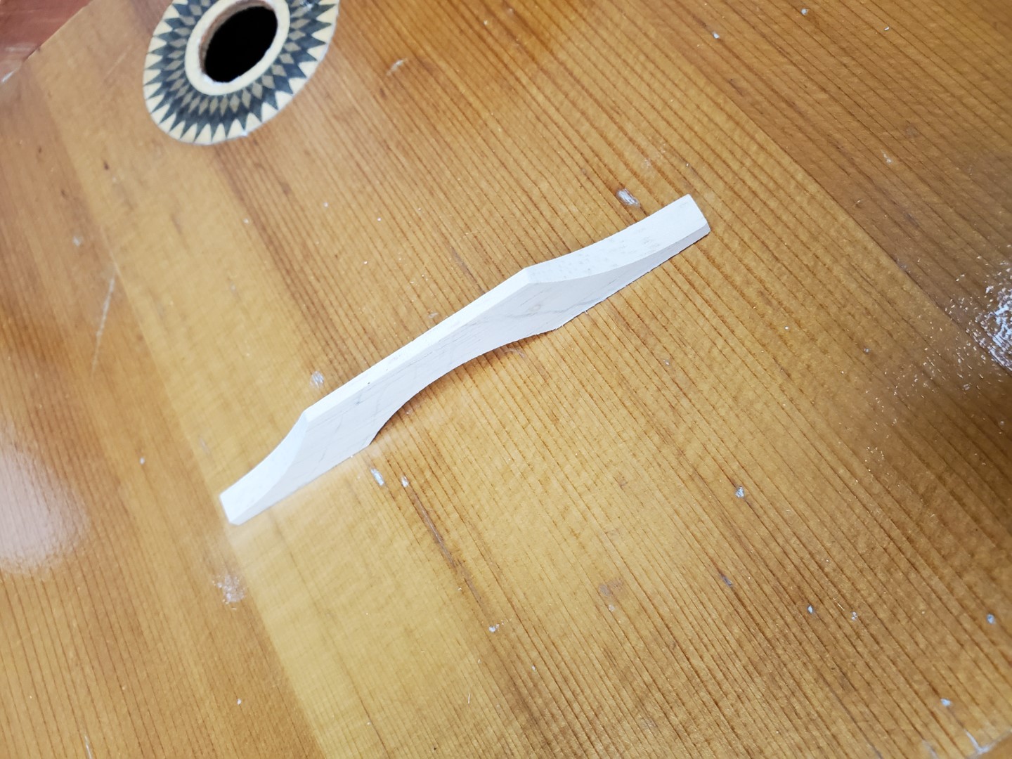
– Bridge – The bridge was missing but I found dimensions that seemed to match the shadow that had been left by the original bridge; I used these dimensions and some reference photos online to make a replacement out of a scrap of maple. This was very quick work with the belt sander.
– Strings – This was the easiest part, available online.
With the parts replaced we were able to tune it and it seems to play OK…

With an endoscope camera I was able to find two labels inside:

Left Translation: Balalaika. Article #205. Airbrush method finish. Nationwide Standard of Russian Soviet Federative Socialist Republic 83-72. Price 6 rubles 70 kopeks. Leningrad, 15 Chapaev St.
Right Translation: Ministry of Local Industry of Russian Soviet Federative Socialist Republic
Main Directorate of Production of Musical Instruments
Lunacharsky Factory of Folk (plucked string) musical instruments
Leningrad
The left label is also stamped with a 1973 date
Window Crank Adapter
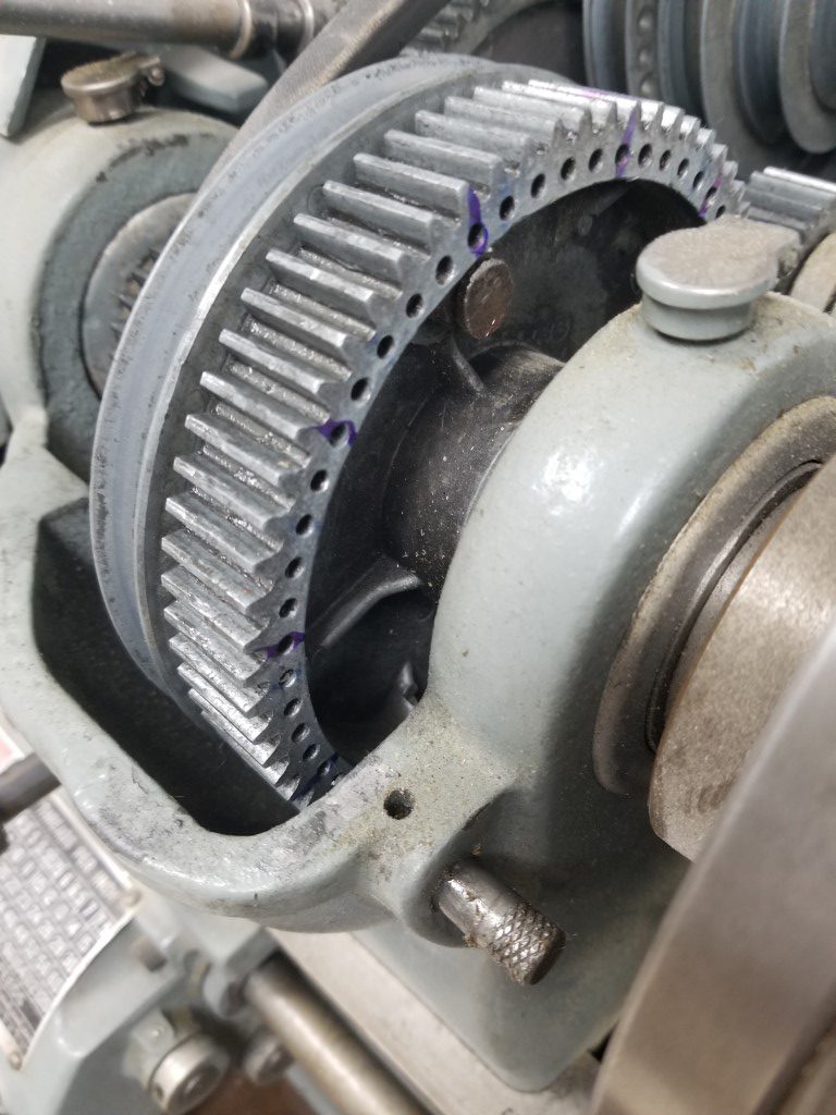
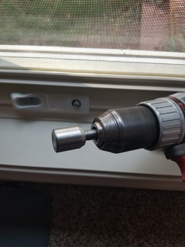
It’s not particularly hard to use a window crank, but multiplied by several windows it does take a little bit more time than it could. With this in mind I created an adapter for a cordless drill to more quickly open/close windows, particularly as it’s starting to cool down some and we’re using the windows more.
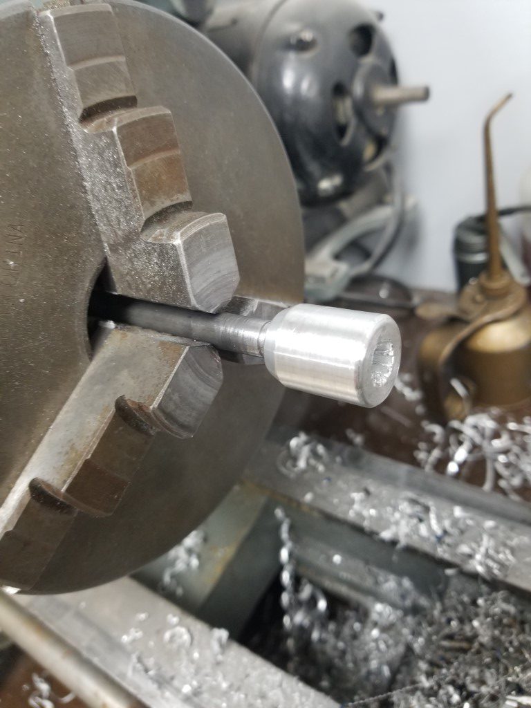
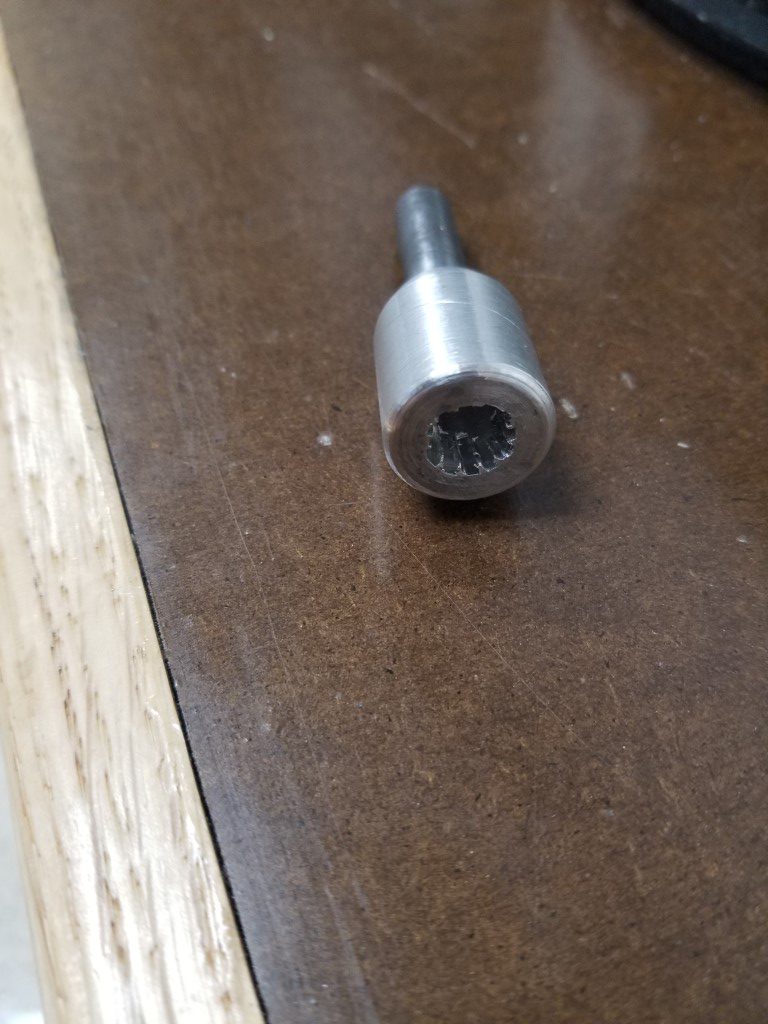
Construction was relatively straight forward, it’s just a bit of aluminum turned to size and with a hole drilled with the same size as the OD of the splines on the window crank mechanism. The only tricky part was creating the splines since this is the first time I’ve attempted it. The lathe has a built-in index plate that allowed the adapter to be positioned in the 12 evenly divided positions required; once it was in each position I used a small lathe tool to broach a slot, moving the carriage back and forth with the lathe off while slowly raising the tool. I then turned a bit of steel rod to size and pressed it into the back of the adapter.
Overall it turned out OK – the splines aren’t the greatest due to the tool not being very rigid, but it’s plenty good enough for it to engage with the window and hold solidly.

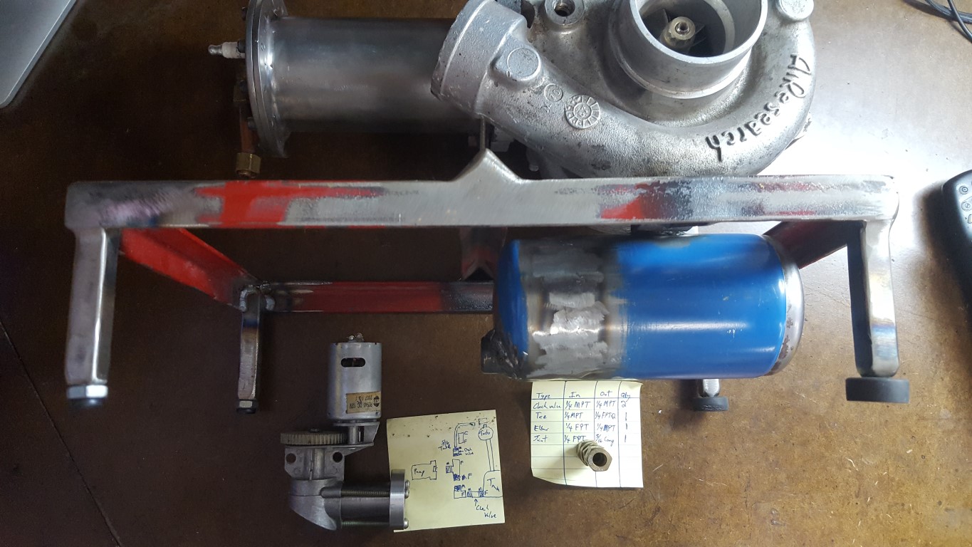
Jet Engine Oil System
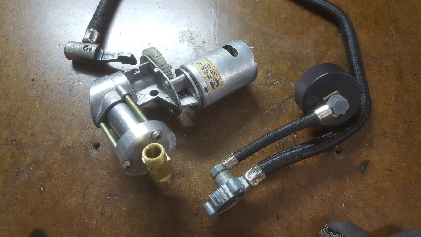
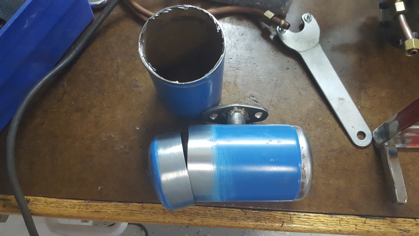
This weekend I resumed work on the jet engine project. When I last left off I had just completed the frame and mounted the turbocharger/combustor. I had also fabricated an oil tank out of an old propane tank and mounted it under the turbo, but had hit a bit of a wall with what to do for an oil pump. There are electric oil pumps available, but basically all of them would be overkill for this application. Also, since this is a hobby I’d much rather put in the time to make something custom vs paying for parts. Turbocharger jet engines have been done by many others, my approach with this is to see how compact and well packaged I can make one – that doesn’t happen by bolting together a bunch of off-the-shelf parts.
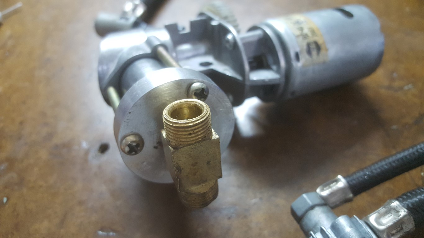
I had considered using the bus’s old oil pump, but this created more problems than it solved (connection of inlet/output pipes would be a challenge as would driving it and selecting a motor). Today after a taking a fresh look at it I realized that an old 12V tire inflator pump that I had could be adapted to work. The plastic casing had broken, but the ‘guts’ were all metal and should hold up to oil pump duty. The only problem was that the cylinder head of the pump had no way of connecting an inlet pipe – being designed for air, it just drew in air from a small hole. To fix this, I made a new cylinder head on the lathe with one large hole in the center. A tee fitting screws into the head and I’ll put a check valve on each side. This larger single-hole head should also help compensate for the increased load of pumping oil, much thicker than air. Once I start running oil through it I may have to make some tweaks to avoid overload (lower voltage, thin oil, etc) but this at least gives a path forward for experimentation.
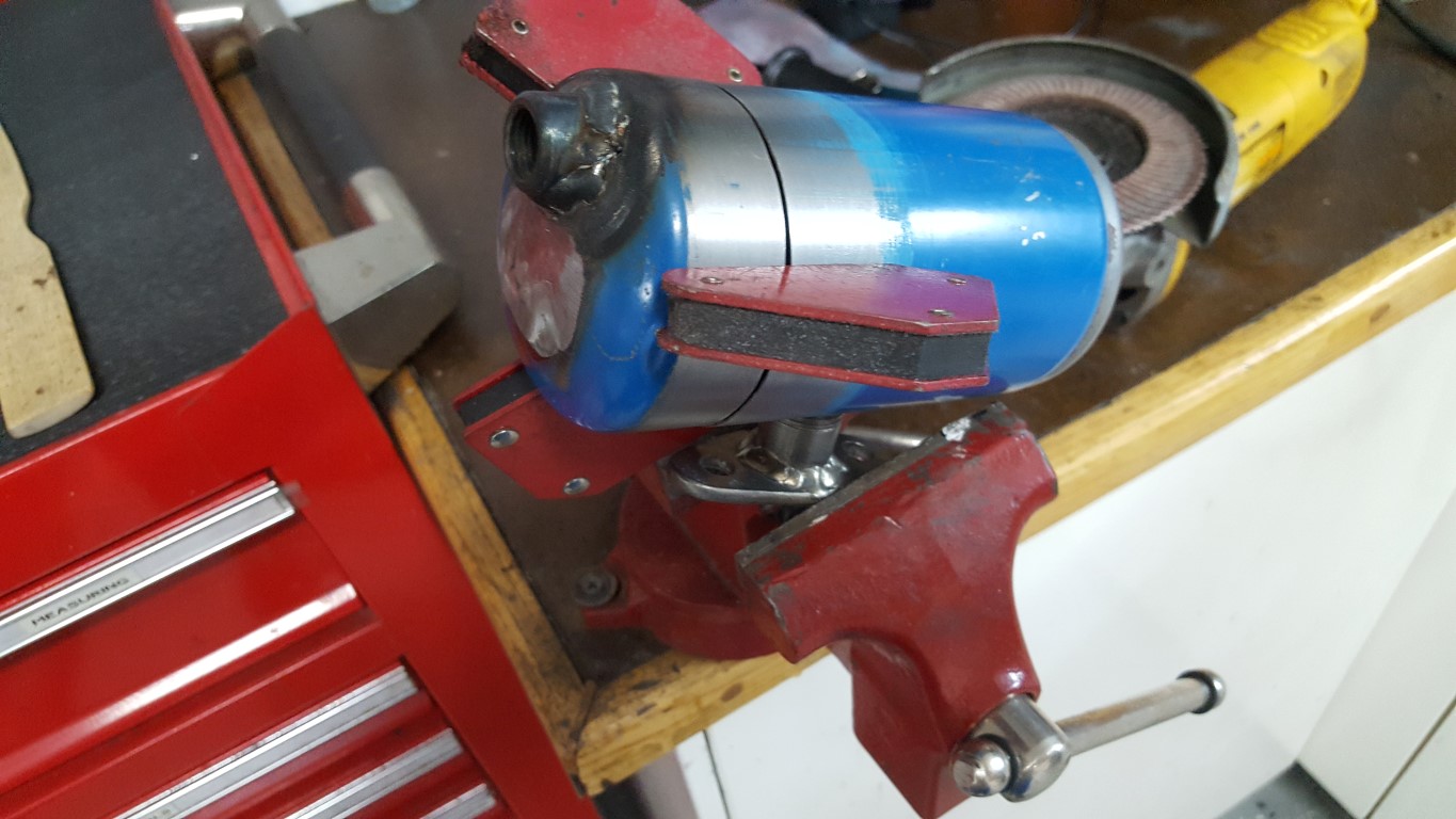
I also shortened the oil tank to make more room underneath for other support systems and made a threaded port on the lathe to weld into the tank to connect the oil pump. The welds aren’t the greatest looking, but are leak-free and that’s what matters – they should clean up OK after some grinding. For now the whole project is in fabrication mode, but once everything is in place and working I’ll go back and do body/paint work on all the parts to make it look nice too.

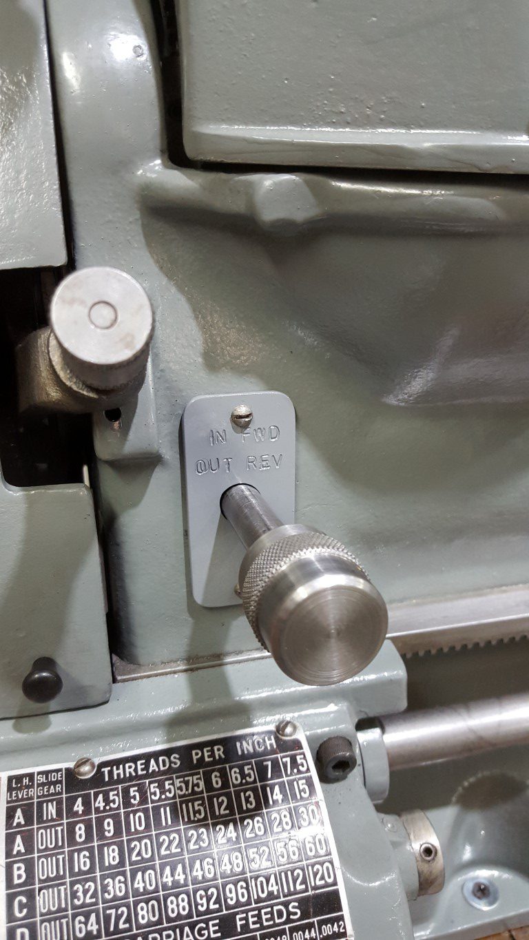
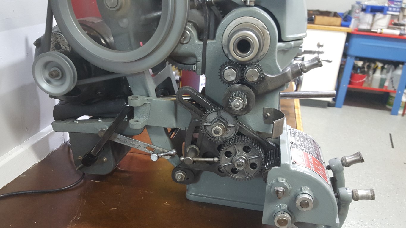
Atlas/Craftsman Lathe Reversing Switch – Finished
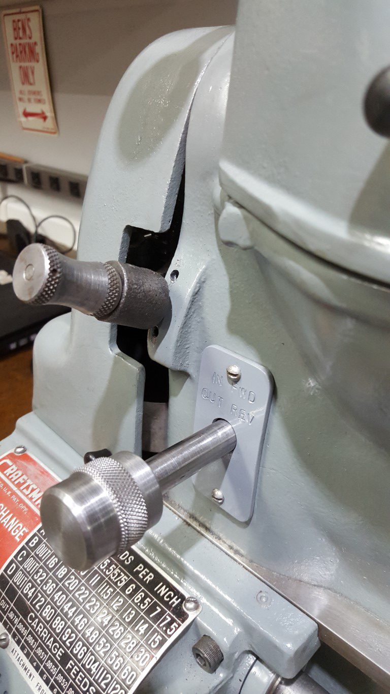
Tonight I finished up the lathe reversing switch linkage by stamping and painting the cover plate and making a knurled knob that roughly matches the others on the lathe. The lathe allowed the inside diameter of the knob to be bored precisely enough to get a good interference fit on the shaft – no need for any fasteners.

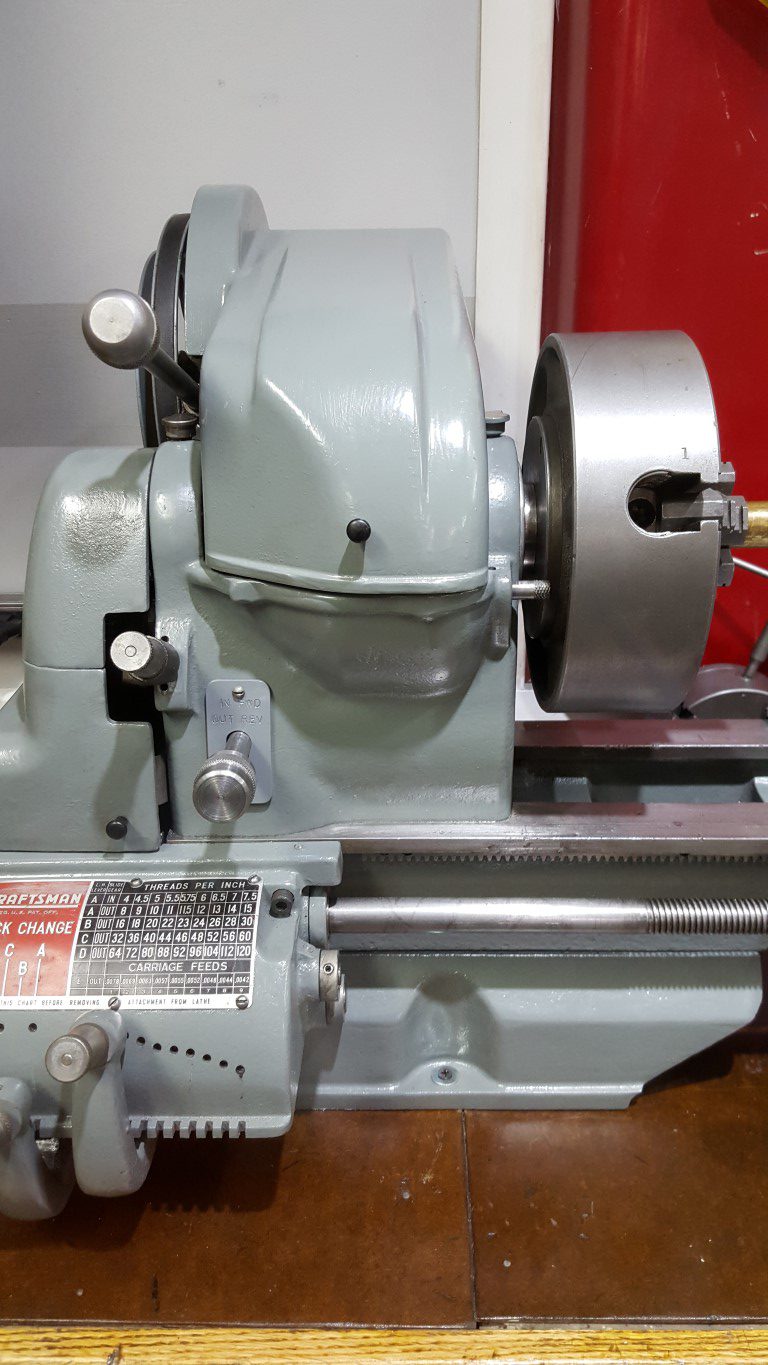
Atlas/Craftsman Lathe Reversing Switch
Originally the Atlas/Craftsman lathes spun in only one direction; because of this they came with only an On/Off switch integrated into the lathe’s headstock. At some point in my lathe’s past the On/Off switch was removed and a reversing ‘drum switch’ added. The drum switch gives the flexibility to spin either directions for special uses (cutting metric threads, power tapping, etc) however it’s it’s too big to fit in the lathe’s headstock.
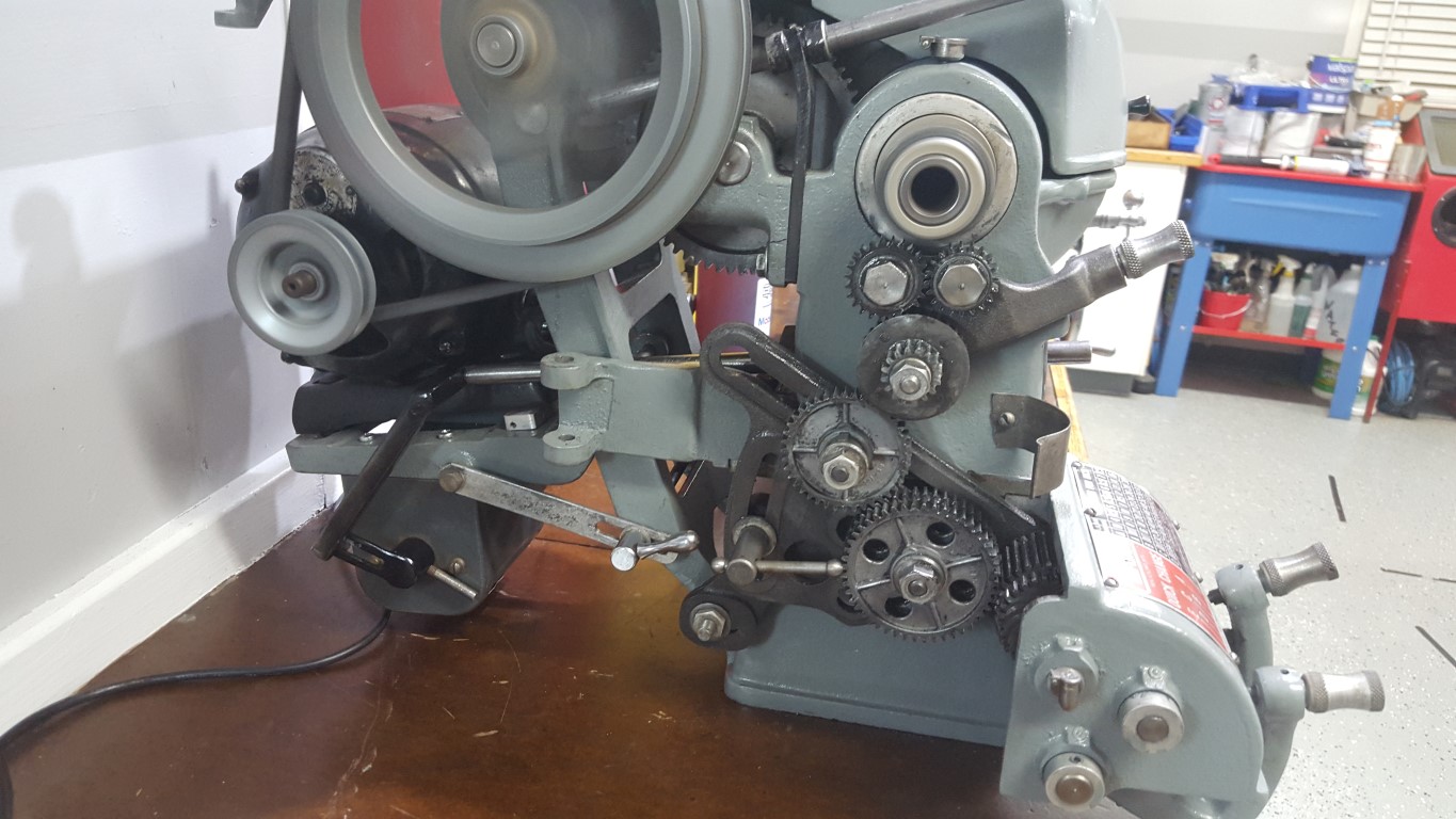
The previous owner had the switch mounted on a wooden arm extending up from the lathe’s workbench; re-using this idea would work but since I’ve moved the lathe to the shop countertop the arm would need to be rebuilt and I also don’t like the aesthetics or the need to reach over the spinning work to turn it on/off. Another option would have been to mount the switch under the lathe base, however for the carriage to clear the switch would require raising the lathe – it was already at a good working height and raising would effect stability/rigidity as well as being susceptible to dripping oil. Lastly, it could have been mounted just anywhere on the ‘outside’ of the lathe (on a guard door, past the tailstock, etc) – none of these locations seemed great and overall this just seemed like giving up.
So what I ended up doing over the past few nights was locating the switch in the only volume of space just big enough for it, under the motor. This location has the added benefit of making the wiring short and simple. As-is, this is of course very inconvenient, but I chose it with creating a linkage in mind. The addition of the linkage allows the original On/Off switch hole to be utilized (previously this was just an open hole), puts the control in a convenient place, and makes it look like it was designed this way. The linkage was a challenge and took a few iterations to get right. It consists of a 1/2″ OD steel tube that runs through the headstock, supported by two metal plates I fabricated. At the end of the tube I welded on a nut to accept a bolt that bolts on another arm I fabricated. The arm has a bolt welded through it that engages with a slotted lever welded to the drum switch’s lever. The resulting contraption actually works very smoothly: pushing IN runs the spindle forward, pulling OUT runs it reverse, and returning to center is Off. All that’s left to do is create a matching knob and mark/paint the switch plate.

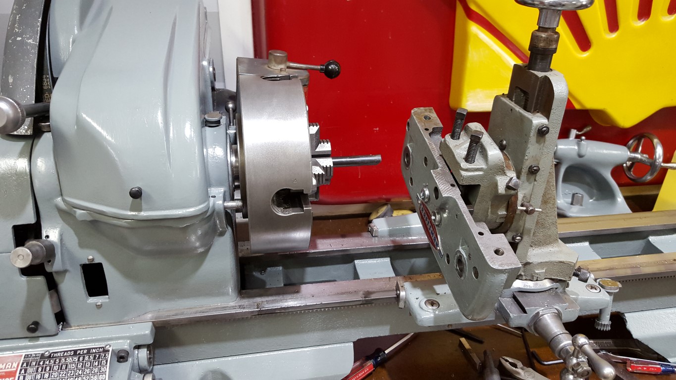
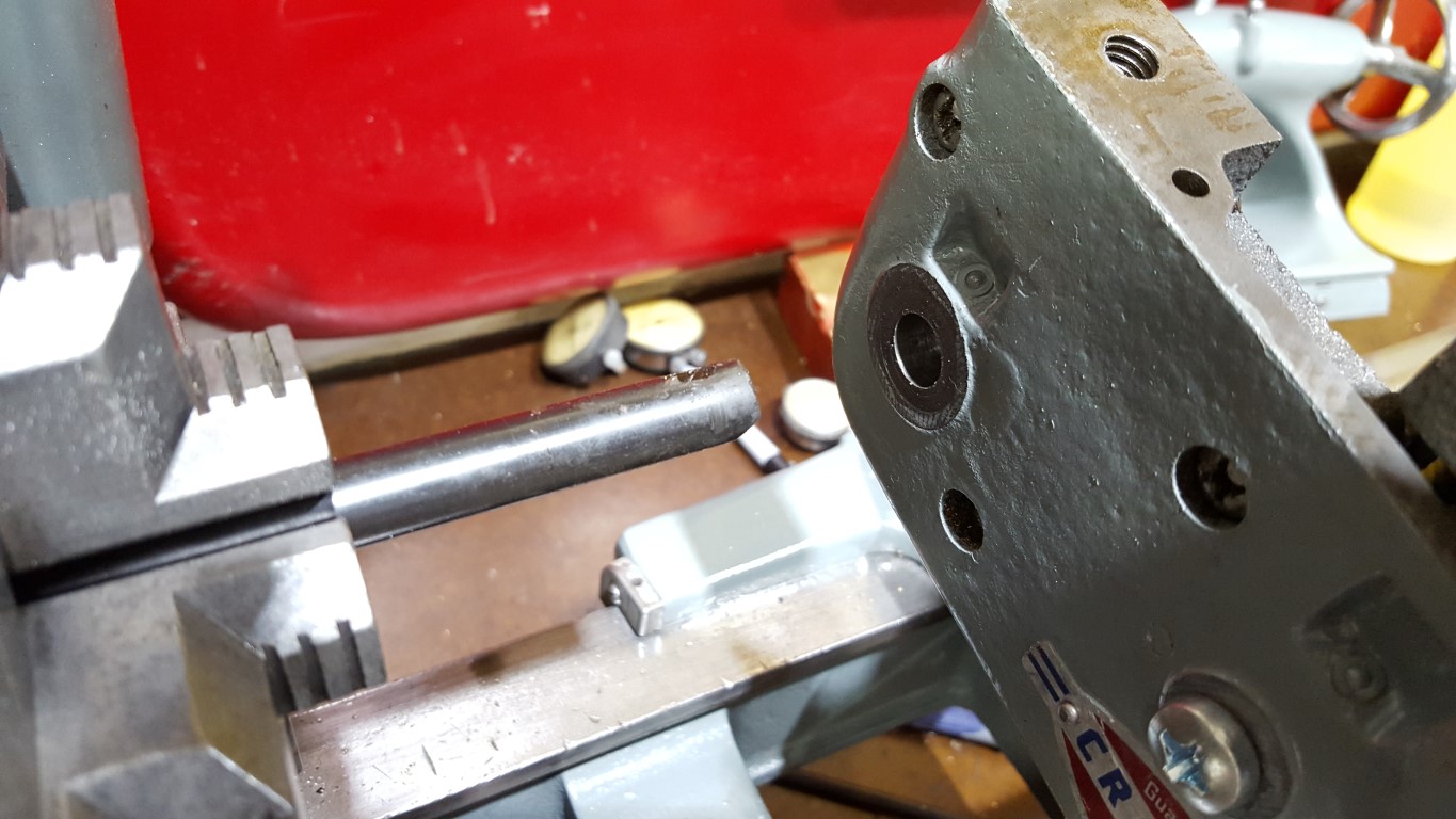
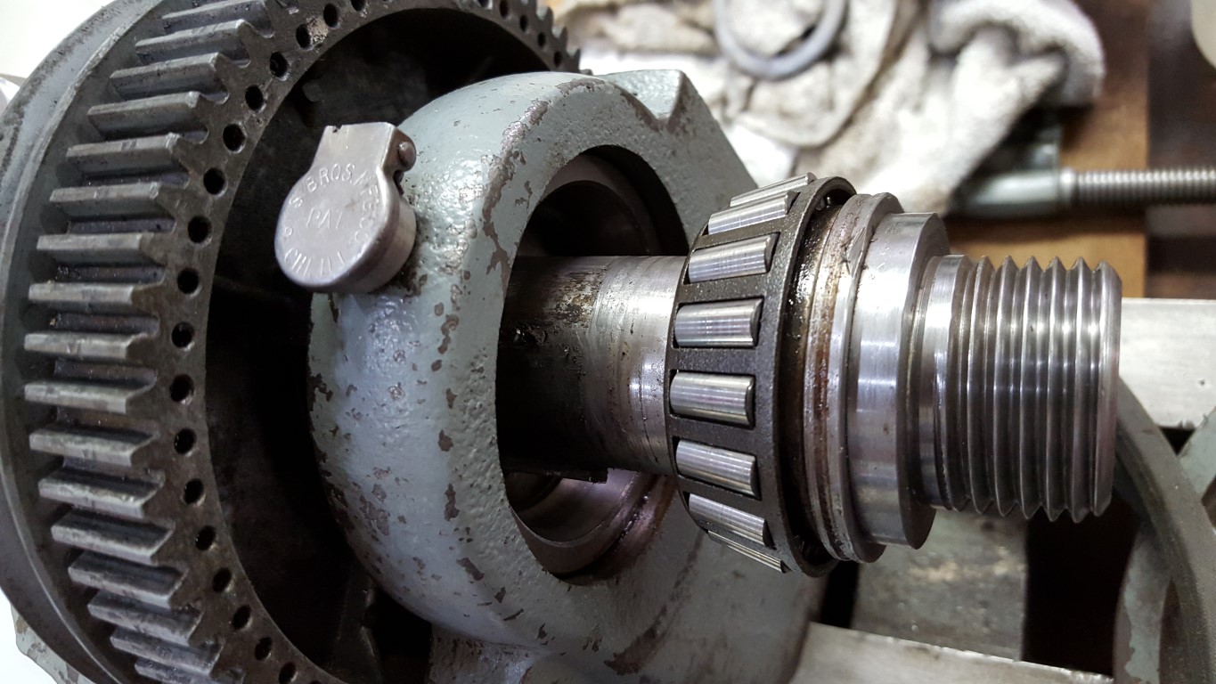
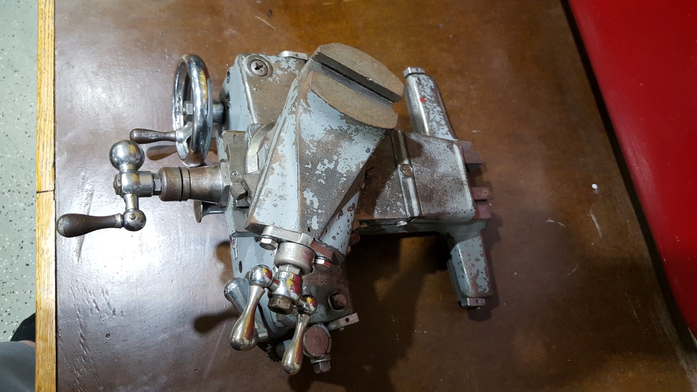
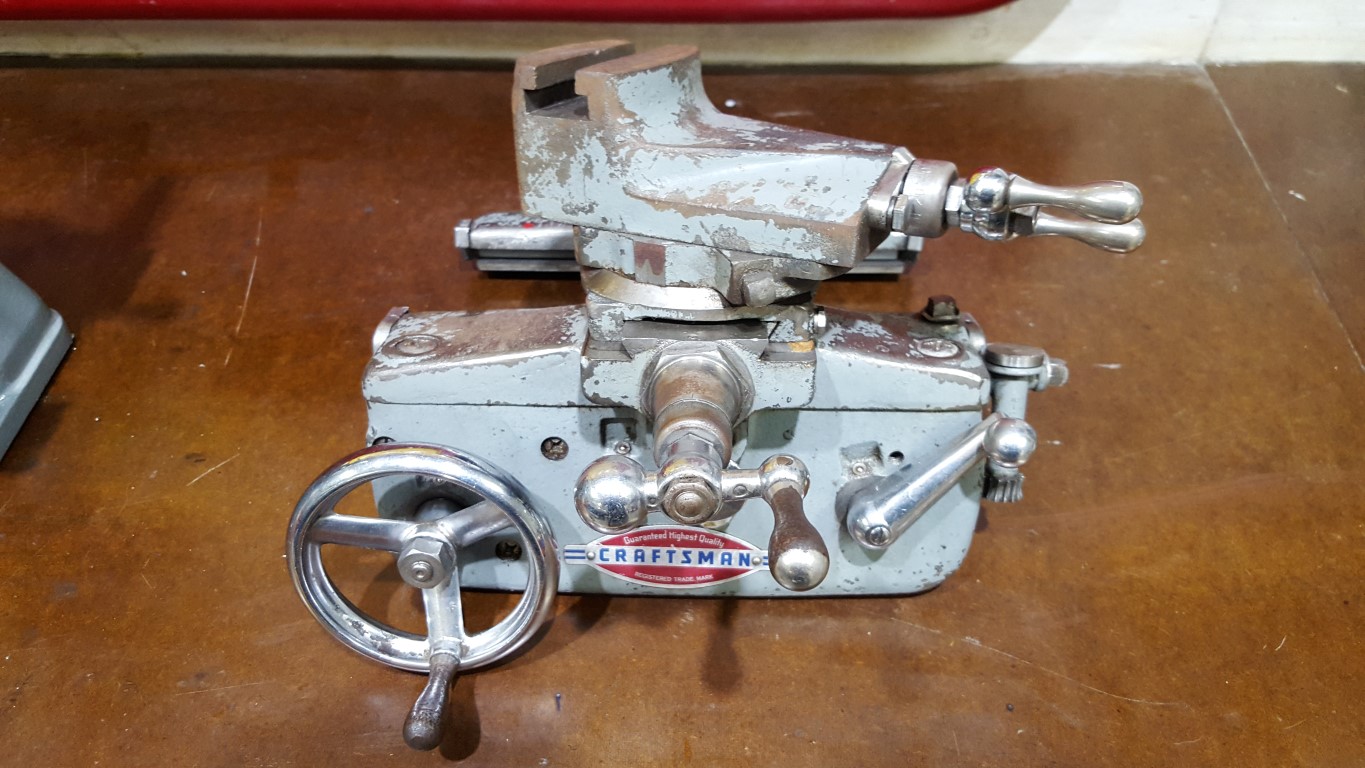
Atlas/Craftsman Lathe Carriage Hand Wheel Fix
The hand wheel for the carriage (longitudinal/Z axis) of the lathe had a bit more up/down slop than I liked. To remedy this I used the lathe to fix itself. First the ‘apron’ (front plate) was removed from the carriage and mounted in the milling attachment, the smallest boring bar that came with the lathe was used to widen and true to the hand wheel hole. Similarly, I skimmed the surface of the hand wheel shaft to ensure it was perfectly round. With the larger apron hole and slightly smaller shaft I was able to create and fit a brass bushing to take up the space between. The outside diameter is a press fit into the apron and the ID has about 0.002″ of clearance to allow it to turn but without the slop previously seen. I only took pictures of the first step, I’ll take more for future lathe projects.
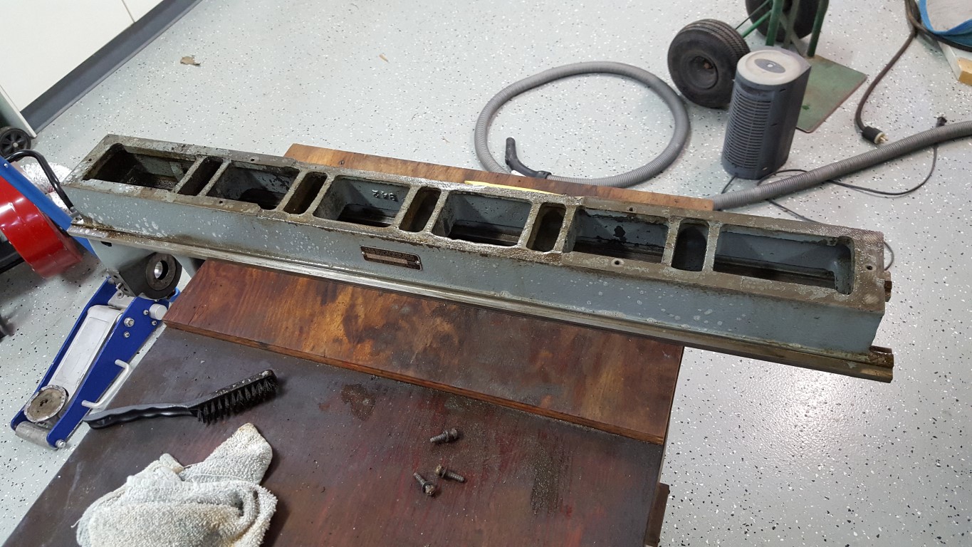
Atlas/Craftsman Metal Lathe
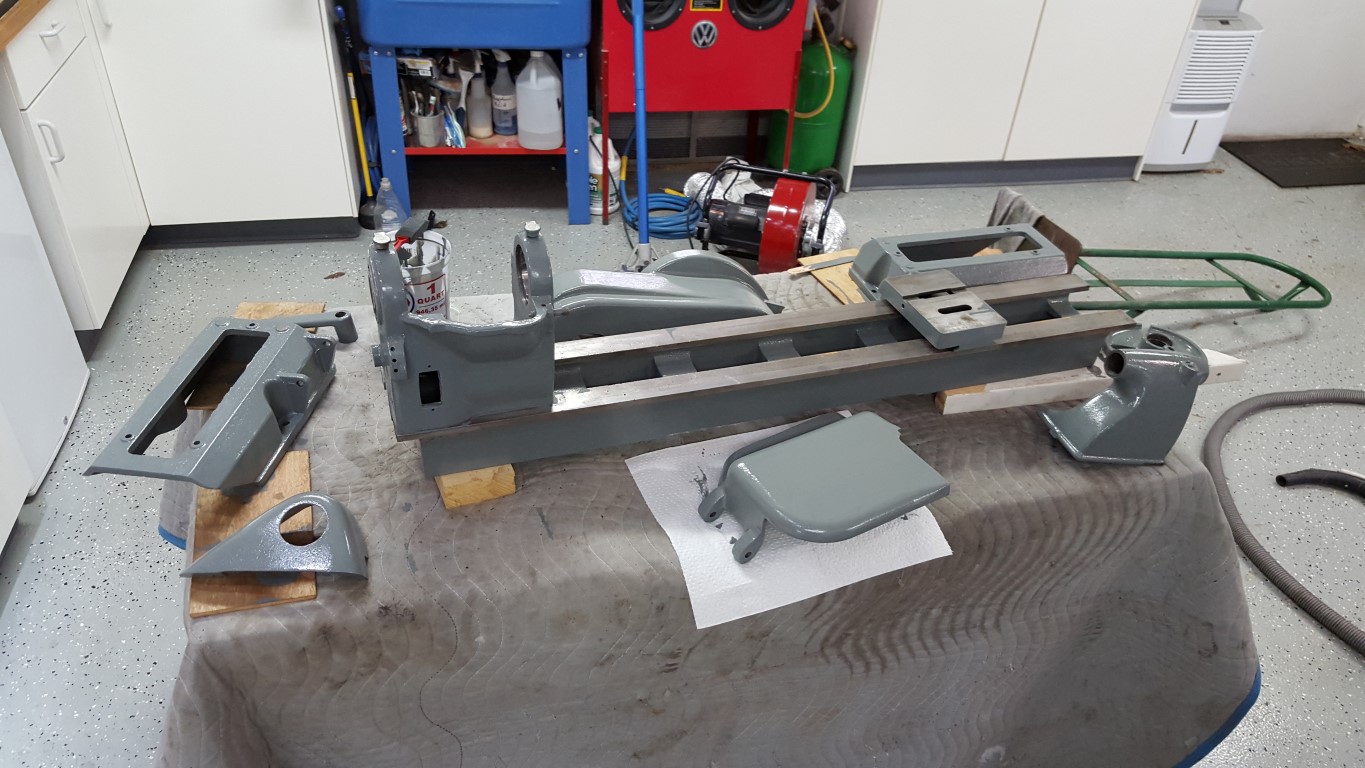
This winter I’ve done some much needed cleaning and painting of the garage; it’s survived the bus restoration and countless other small projects. This has put the jet engine project and bus transmission on hold, but I’m in no particular hurry with either.
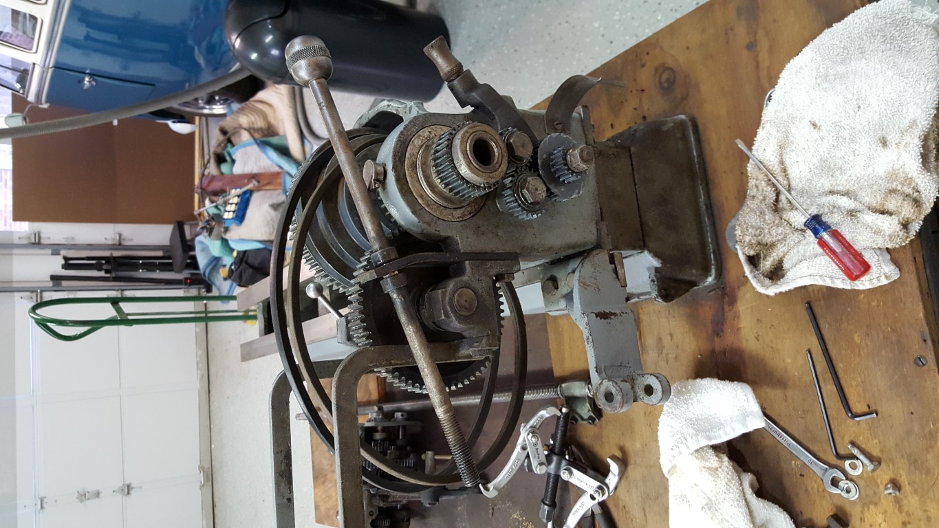
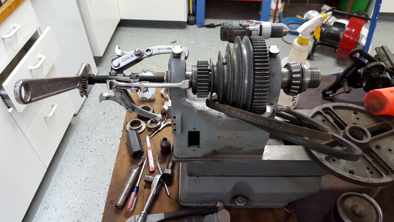
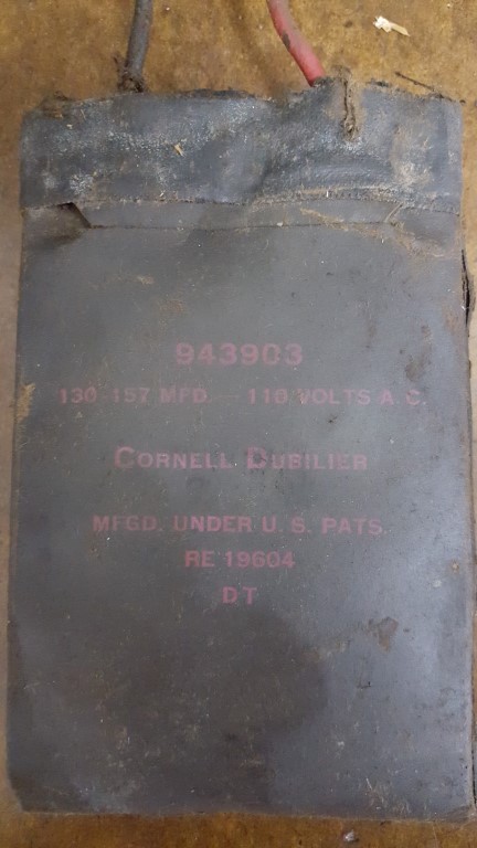
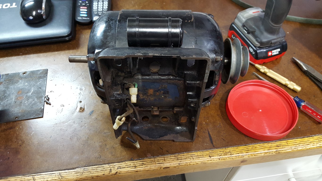
Also, recently I picked up an old Atlas (Craftsman) lathe I found on Craigslist with lots of tooling. This style of late was made by Atlas from the late 1930’s through the late 1950’s; based on the numbers engraved in this one’s bearings it seems to have been made around 1956. The manual that came with it was published in 1967; but I later found a receipt for the manual, proving that it was a replacement and explaining why the lathe in the manual looks like the late 1950’s through mid 1970’s version – both machines have all the same features and function the same though. For the most part it was in good shape and only needed some heavy cleaning, repainting, and a new motor capacitor; there are a few mechanical areas for repair/improvement that I will tackle, but nothing that prevents it from operating now. The original motor used a flat capacitor that’s no longer made in it’s motor base, so I had to get a little creative with mounting the replacement on the side of the motor.
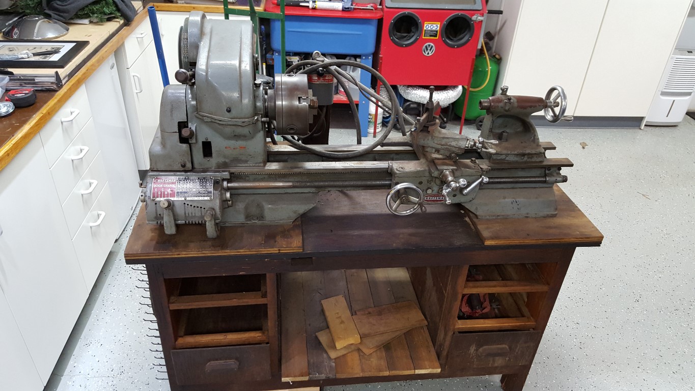
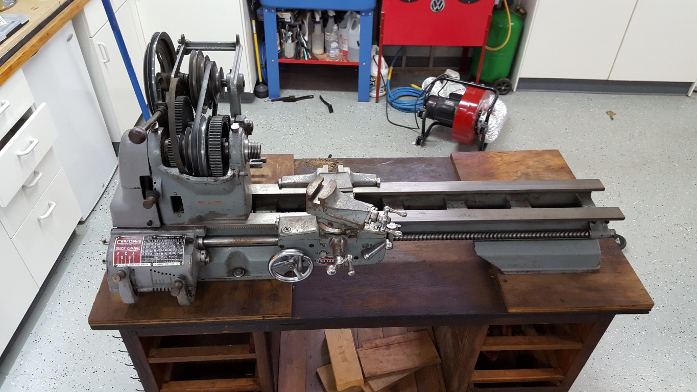


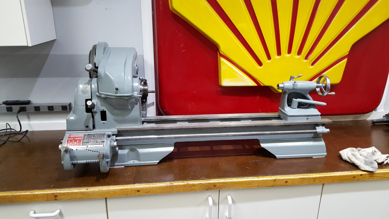
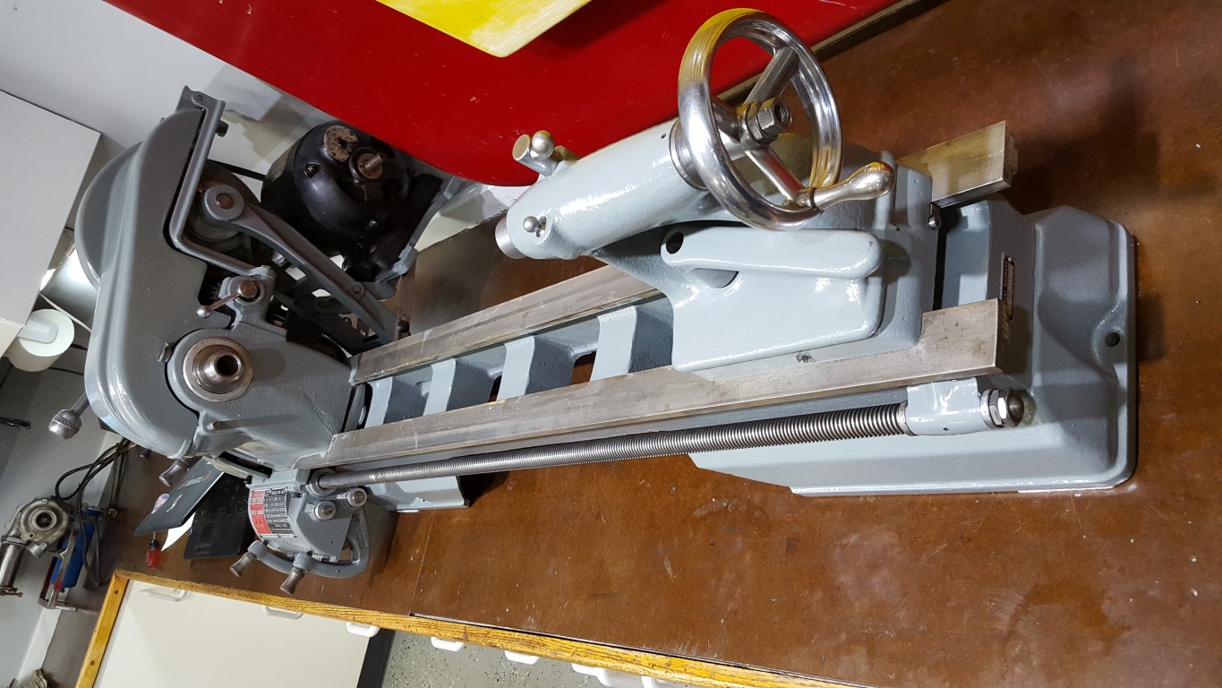
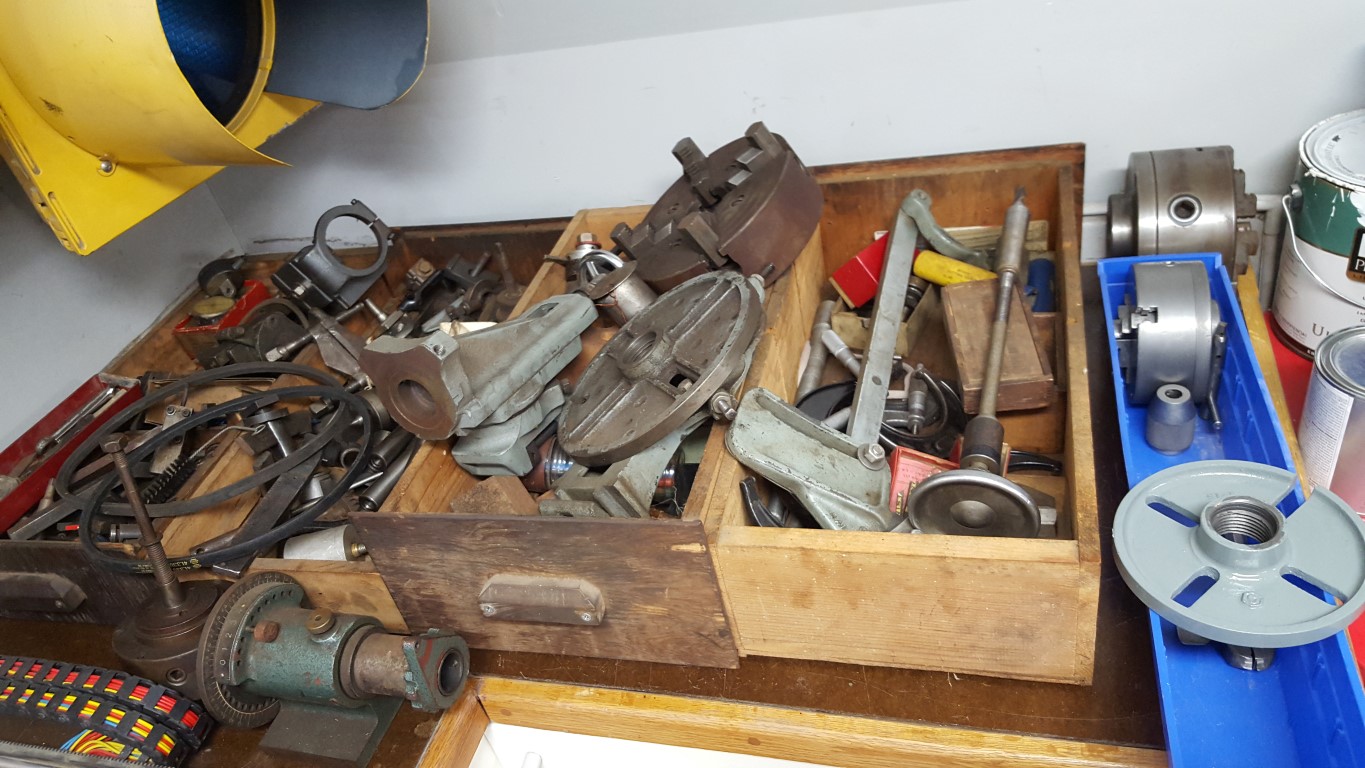
No particular project in mind for this, but no doubt it will come in handy with other projects especially since it has the milling attachment allowing it to serve as a small mill as well.
