Piano Automation Begins
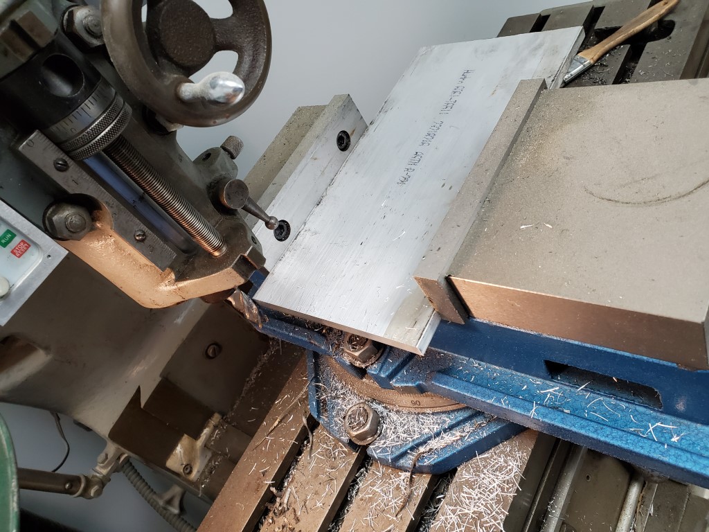
This weekend I designed and began fabrication of the parts needed for adapting the solenoid valves to the piano’s tracker bar. This adapter will consist of two 3/8″ aluminum plates. The top plate will have holes to accept the solenoid valves, and the bottom plate will have holes to interface with the piano’s tracker bar. Grooves will be machined into the bottom plate to create airs channel between the tracker bar holes and the solenoid valves above. The two plate will then be sealed together, covering the grooves; a similar construction technique as some carburetors. As long as the grooves are carefully routed, each valve should connect to exactly 1 tracker bar hole.
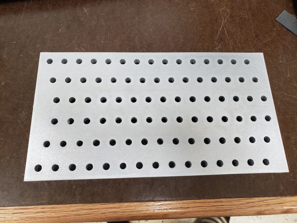
I cut the 3/8″x6″ plate on the band saw and then milled to final length. I used an edge finder to locate the plate edges, and then used the mill’s digital readout to position above each row/hole. For each row I took 2 passes, first spot drilling with a center drill and then drilling to size with a twist drill. 88 * 2 plates * 2 passes = 352 cycles of positioning the X axis and drilling a hole. Once all the holes were drilled I sanded sides to remove burrs from the holes and scratches from the rough plate.
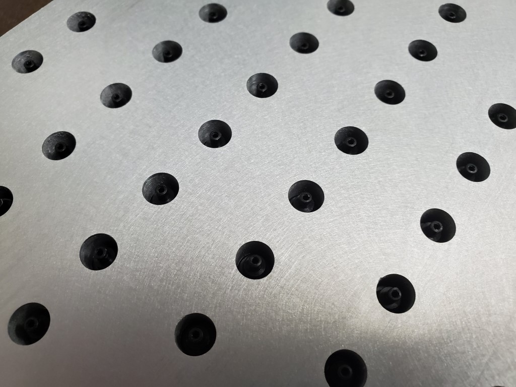
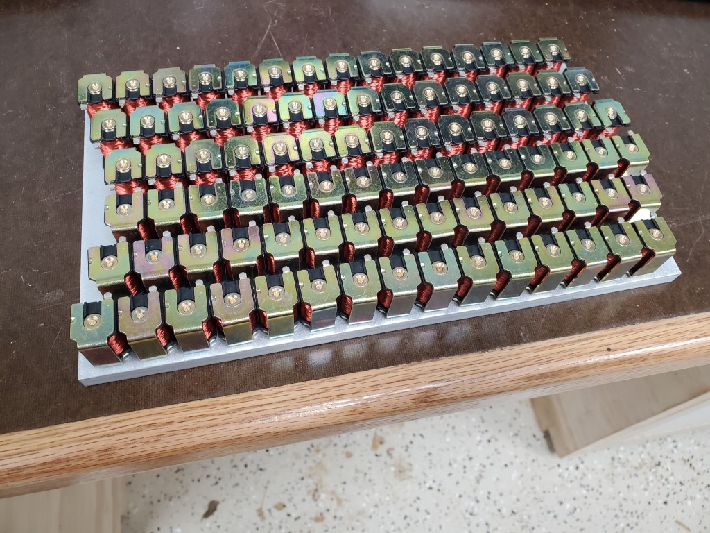
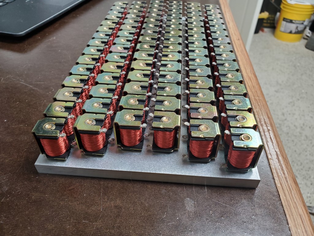
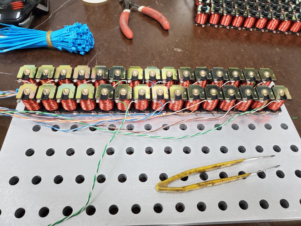
Next I installed and wired the solenoid valves in the top plate. The solenoid valves are an exact fit to the hole, but I added a bit of CA glue to ensure they stay in place. Wiring consists of scrap Ethernet cord that’s been stripped back; Every ~7 solenoids each share a common wire to reduce wiring, but it’s still ~100wires.
I’m happy with the results so far; this is by far the most precise thing I’ve made on the mill and everything is lining up perfectly. The next step will be to 3D model the grooves and convert these to paths to run on the CNC router. I’ve done some aluminum milling with it previously so it should work out OK, especially since it’s just cutting the shallow grooves – I wouldn’t have trusted the router to drill the holes as well as the mill did.


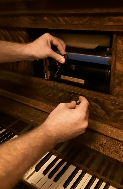
Piano Automation Proof-of-Concept
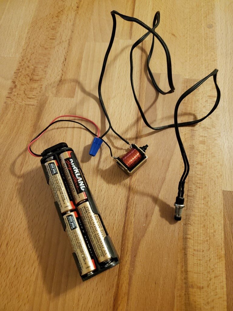
I did a quick test tonight to check/confirm the feasibility of using the ebay solenoid valves I got a while back to control the player piano. I connected one of the valves to a 12V battery pack and a push button, and then held it in front of one hole of the piano’s tracker bar while the rest were taped closed. When I pressed the button, the valve opened, and the piano played the key! With this successful test I can move forward with designing an adapter to connect all 88 valves to the tracker bar.
Generator Install
After fixing the generator last year (this project) I needed to install it permanently. I pulled the permit last year and it expires soon, so lately I’ve put more work into this to get it done. After a year of on-and-off work it’s finally ready for inspection. Permanent installation consists of 3 main parts: mounting the generator, installing an interlock, and running cable from the generator to the house electrical panel.
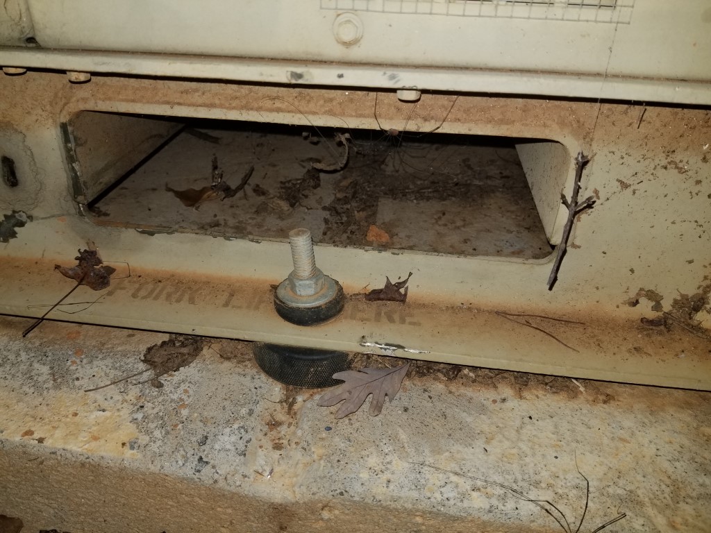
#1 – Mounting the generator was relatively easy – I dug out a flat area, made a form, added rebar, and poured concrete. The only tricky part here was keeping the threaded bolts positioned correctly so that they’d line up with the generator mounting holes. After the concrete cured I moved the generator in place and bolted it down, using hockey pucks as vibration dampers. I turned down the upper hockey pucks on the lathe and machined a step into them so that it keeps the generator centered on the mounting bolts.

#2 – The interlock requirement is the most important part of any generator installation since it prevents energy from the generator back-feeding into the utility, which would create a dangerous situation for the linemen that are working to restore power. There are several ways to accomplish the interlock:
– Automatic Transfer Switch: This switch is placed inline between the meter and main panel, during an outage it automatically disconnects the house from the utility, connects to the generator, and sends a signal to start the generator. This capability would be nice but there’s a lot of complexity, expense, and extra work involved.
– Manual Transfer Switch: This switch is placed inline between the meter and main panel and you can manually select which power source the house is using. This is much simpler than the automatic switch, but still requires an additional small panel for the switch.
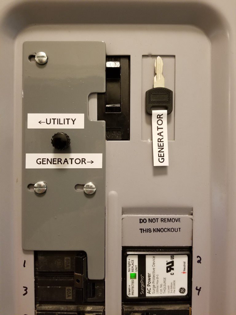
– Main Breaker Interlock: This is a sliding plate that mounts inside the existing main panel and it prevents the main breaker from being ON at the same time as another nearby breaker (and vice versa). The generator powers the main panel through the nearby breaker.
I opted for the Main Breaker Interlock since it’s allowed where I live and it’s the simplest way.
#3 – Running cable was the toughest part. Since the generator isn’t a residential unit that’s fire-rated to be directly next to the house (it probably would perform better than a residential unit, but the military doesn’t do the residential testing) it had to be at least 2ft away. 2ft away would have made for an awkward placement and it would have been in the way a lot, so instead I took it much farther out near the tree-line; leading to a ~60ft long trench. Code requires either 18″ of cover or 24″ of cover depending upon whether or not conduit is used. I opted to use conduit since the shallower trench saved digging effort and also reduced the chance of encountering any other utilities in the process. Most of the digging was through very dense/hard clay and it was slow-going with a trenching shovel. I welded the shovel back together at least a few times. I also experimented digging with the pressure washer, which mostly made a mess. The last 2ft near the house were through concrete; the technique I used for this was to turn the area into Swiss cheese with a hammer drill, break it out with a small air chisel, and then progress down to the next layer. I had been on and off of this effort over the past year and finally finished this weekend.

(#4) Misc things. Since the generator wasn’t originally intended for residential installation there were a few extra things I did to convert it:
– I added cabinet locks to all of the access doors. This isn’t for security so much as it is to prevent anyone that shouldn’t be in there from getting into danger, especially the front door that has the output terminals directly behind it.

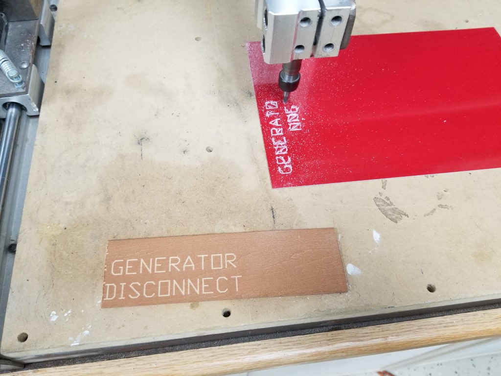
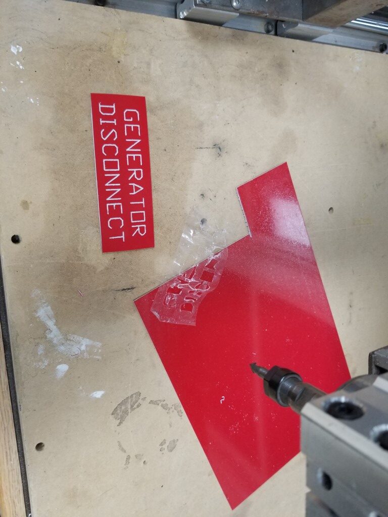
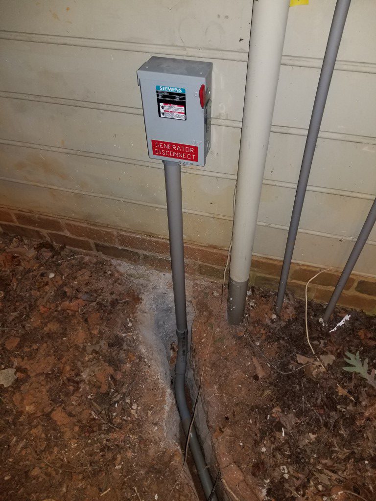
– One of the code requirements is that there must be a way to disconnect the generator outdoors. The generator itself sort-of/kind-of meets this requirement since it has a switch on the operator panel that will open the relay that connects the output power. Since this switch isn’t directly a disconnect though and since there’s a lock on the operator panel that could restrict access I also added a ‘real’ disconnect on the exterior of the house. I used the CNC router to make an engraved sign to mark it.
– Since the interlock completely disconnects the house from the utility it can be tough to know when power is restored. Electrically it would be possible to have a light/buzzer on the utility connections before the main, but since this wouldn’t have a breaker it wouldn’t be safe or code compliant. I found a device that’s made exactly for this problem and installed it. It has it’s own power via a 9V battery and has an antenna that wraps around the line from the utility to monitor power status. The alarm is armed manually when on generator power and as soon as utility power returns its siren sounds.
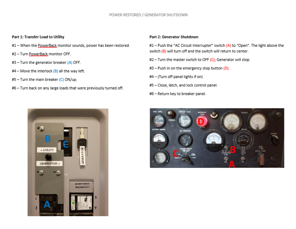
– I made a step-by-step instruction list with photos so anyone that’s home at the time of a power outage can start the generator and operate the interlock. This list and the key to the generator are held inside the main panel with magnets.

Next step is to get it inspected and then I can backfill the trench and clean the mud off of everything one last time.
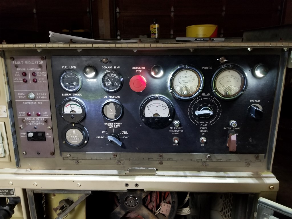
Generator Rebuild
Hurricane Michael hit our area hard and took out power for almost 5 days. Luckily the small generator we already had was enough to keep the fridge running and some lights on, but not much else. The small generator is 120V only, so it also was not able to power the 240V well pump; 4 nights without running water was not fun. It’s not likely we’ll have another outage that’s this long for a while, but we have had a number of shorter outages that seem to indicate that this will be an ongoing problem – a bigger generator would be nice.
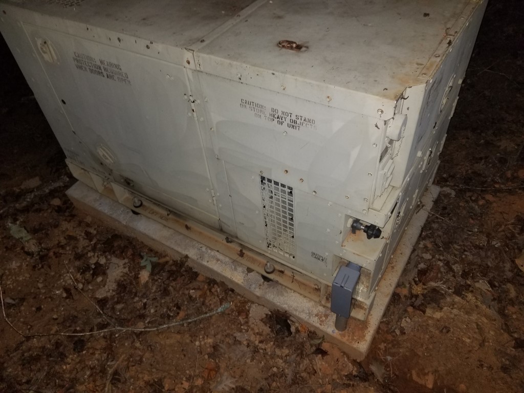
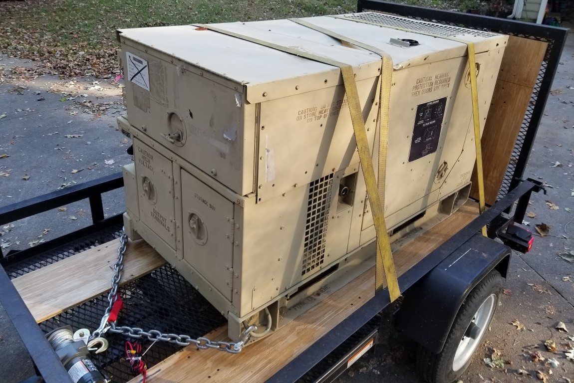
With that in mind we started looking at options; there are a number of ‘off the shelf’ options out there for whole-house standby power, but most of them are very pricey both to install and to run (propane particularly) and we couldn’t justify the cost for something that gets used so infrequently. What did seem to make some sense though was rolling the dice a surplus military generator; the prices are very low (when the condition is unknown), they’re way over-built, and are made to be repaired easily.
I bid on and won an online surplus auction for a diesel generator and picked it up outside our friendly neighborhood military base. It was a fairly easy move at ~1200lb; at pickup I just dragged it onto the trailer with a winch and to offload I tilted the trailer and winched it back down with iron pipes underneath as rollers.
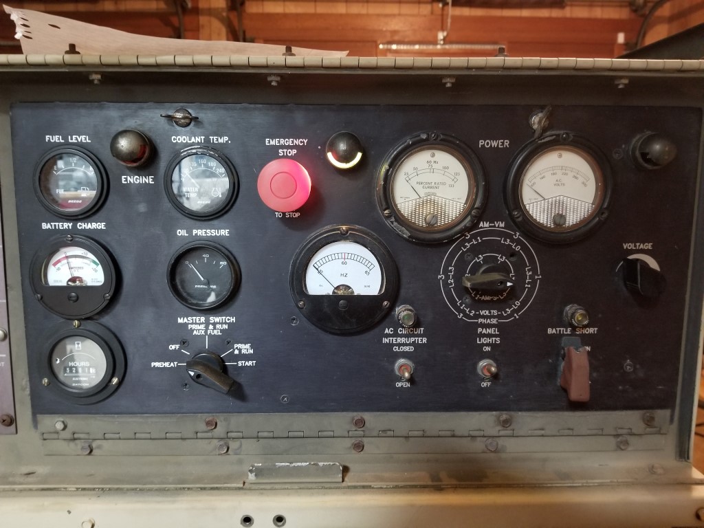
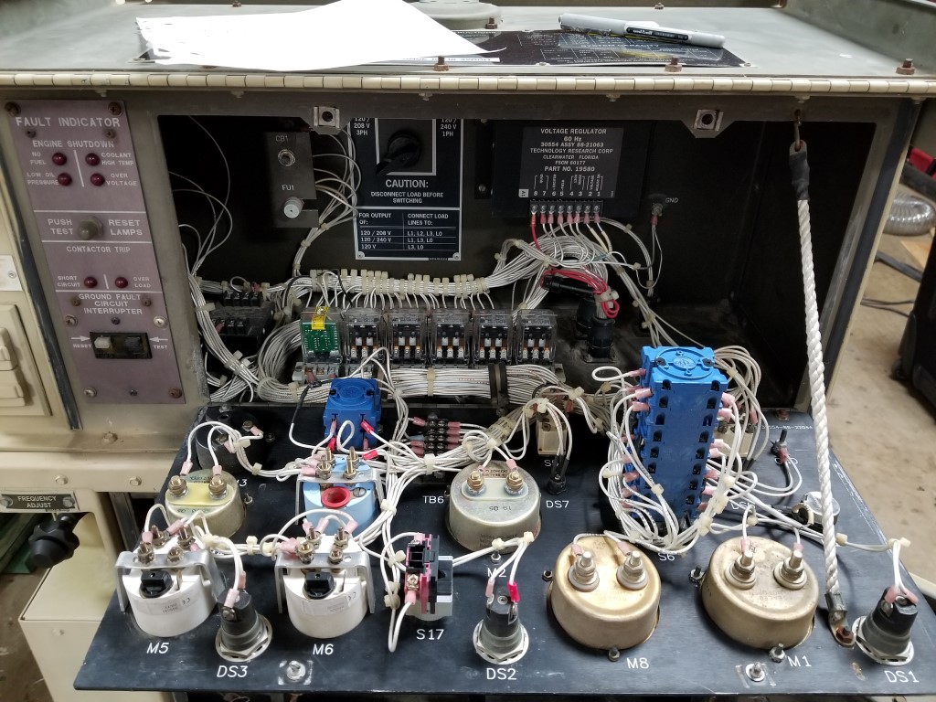
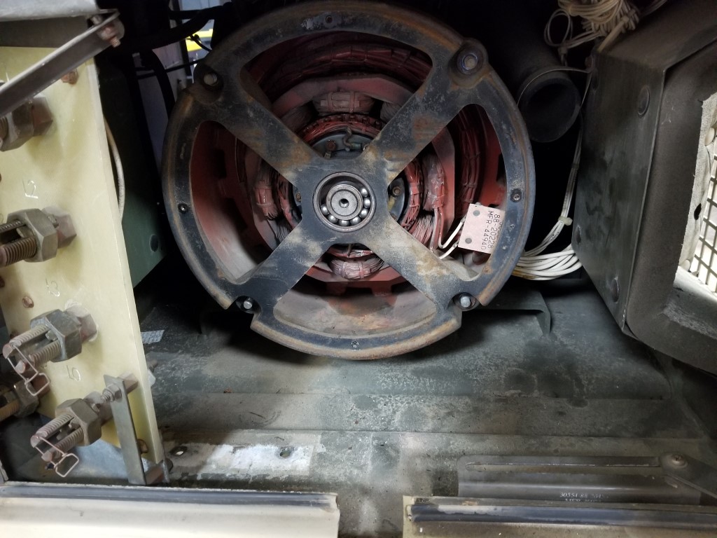
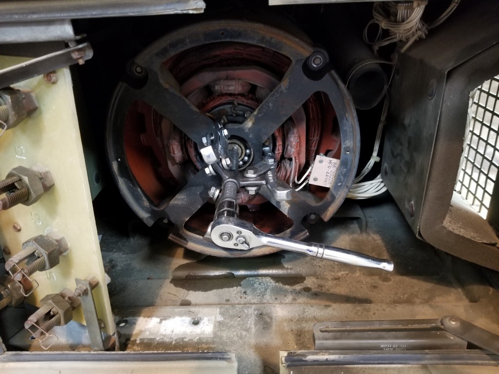
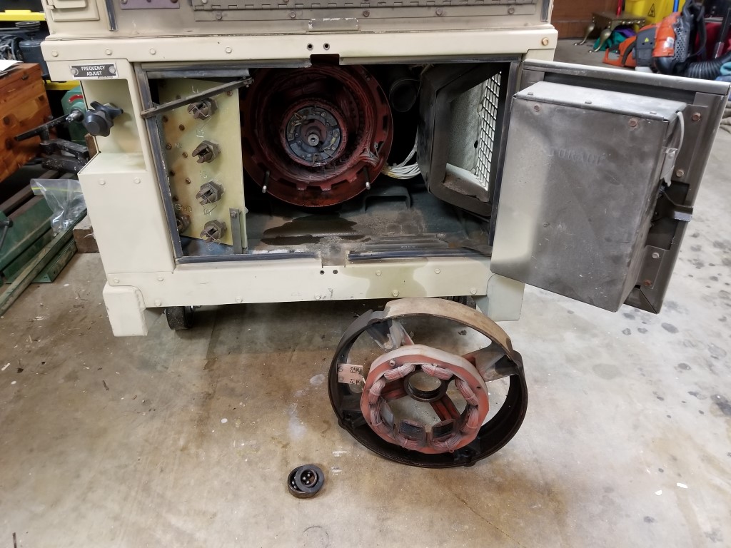
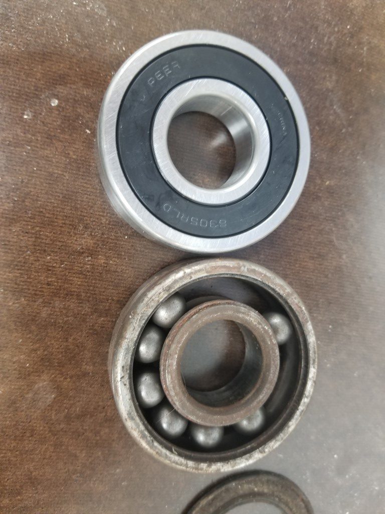
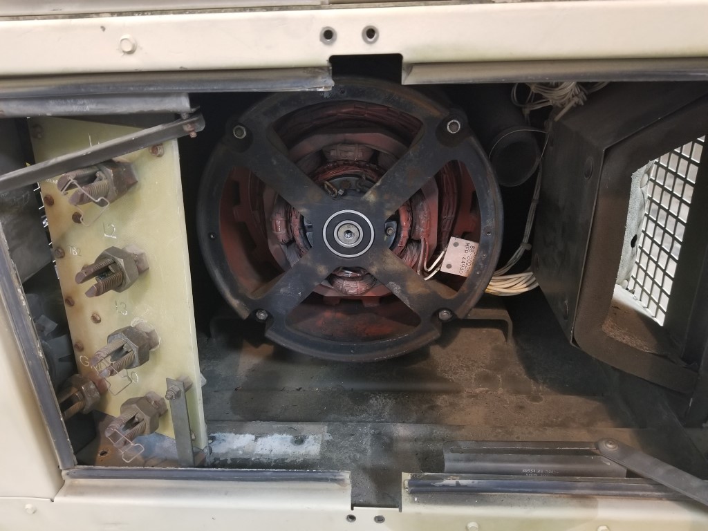
To get it running I first put in new batteries (2x 12v car batteries) and troubleshot some miscellaneous electrical issues (broken connections, dirty switch contacts, etc.). From there it would crank but not run; bleeding the air out out the fuel lines fixed this and it started OK. Once running there was an erratic low frequency rattle that I traced to a bad rotor bearing on the generator head. With this bearing replaced it then ran smooth/quiet. The last issue was twitchy voltage regulation that I traced back to a dirty potentiometer; with this cleaned it held a stable 240V @ 60hz under a variety of loads. Along the way it also got an oil/filter change and a coolant flush/fill.
Altogether this was a very quick project, just a few hours to get everything sorted out. Up next will be setting aside some space for it (probably combined with a new area for trashcans and firewood) and getting it wired in with a manual transfer switch. It’s a “10KW” generator but that rating is on the very conservative side; in reality it’s closer to a 15KW or more consumer unit whose ratings are on the optimistic side. This should be enough to run the lights, TV, well, microwave, and at least one zone of HVAC.
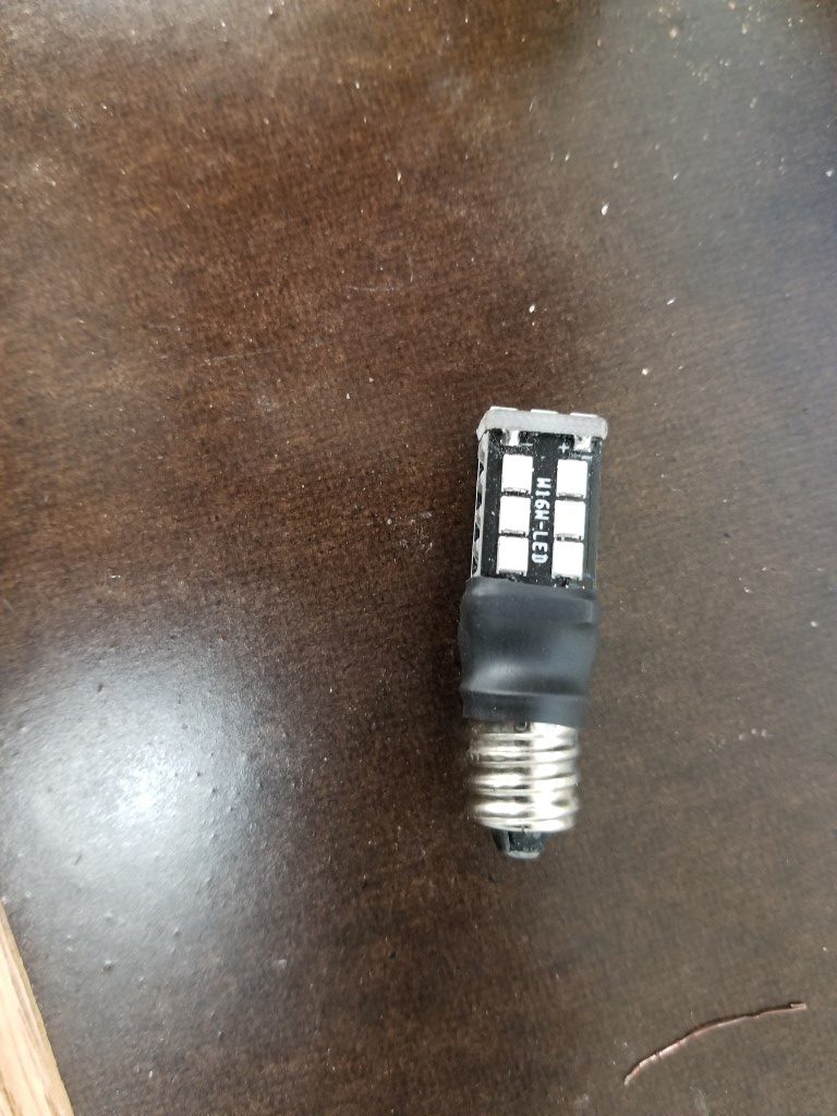
Custom E12 LED Bulbs
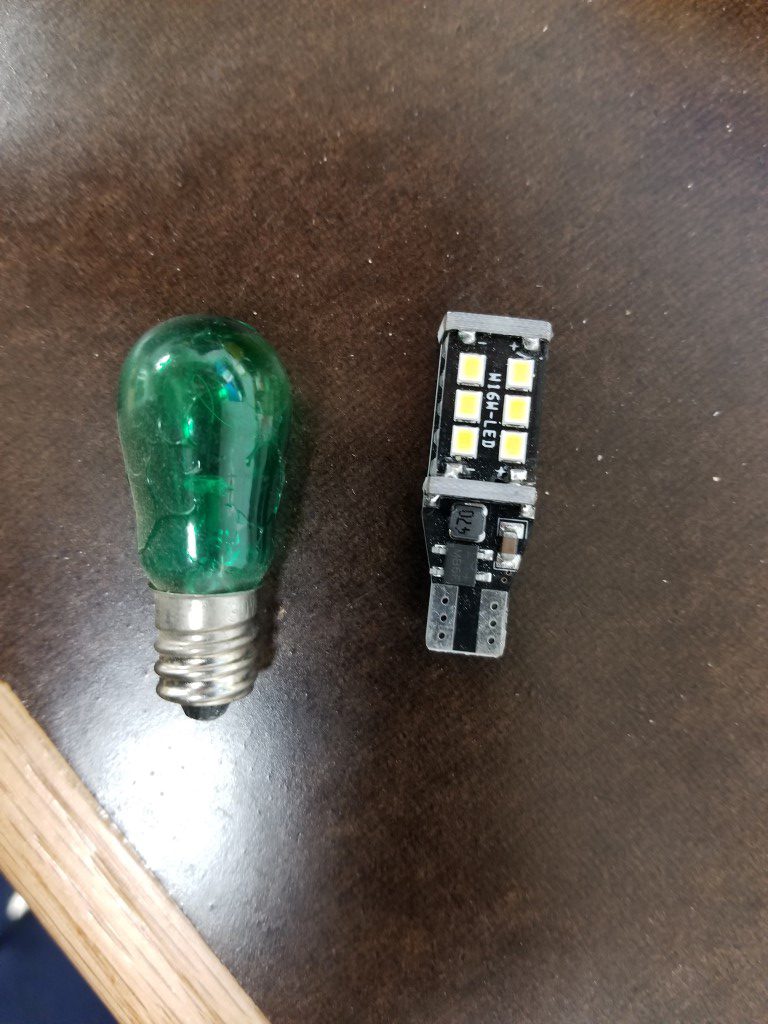
For the generator project (more on that soon) I needed some somewhat specialized replacement bulbs to fix the control panel lighting. These bulbs are 6W / 30V (the generator has as 24VDC electrical system) with a E12/candelabra base. They also have to be very short to fit inside the shades on the panel light holders. The 120V version of this bulb, model “6S6”, is very common and 3-packs were available for a few bucks locally. I knew these would probably be too dim but I picked some up anyways and tried them out. Not surprisingly the 120V filament at 30V barely glowed red.
Since the 6S6 bulbs didn’t work, the next option would have been to order the correct 6W/30V bulbs. The price for these bulbs seemed crazy though, so instead (and for less cost) I opted for a 4-pack of 24V LED lights of a similar size. Although the size if the LEDs was similar, the base type was meant for a wedge connection, so I had to get creative in grafting the LED lights to the E12/candelabra bases.
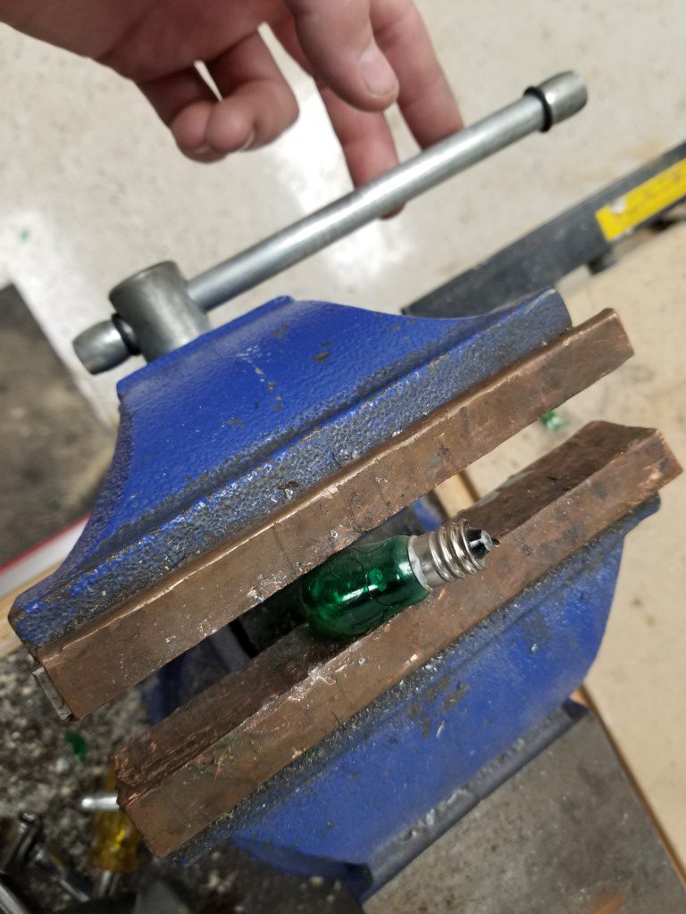
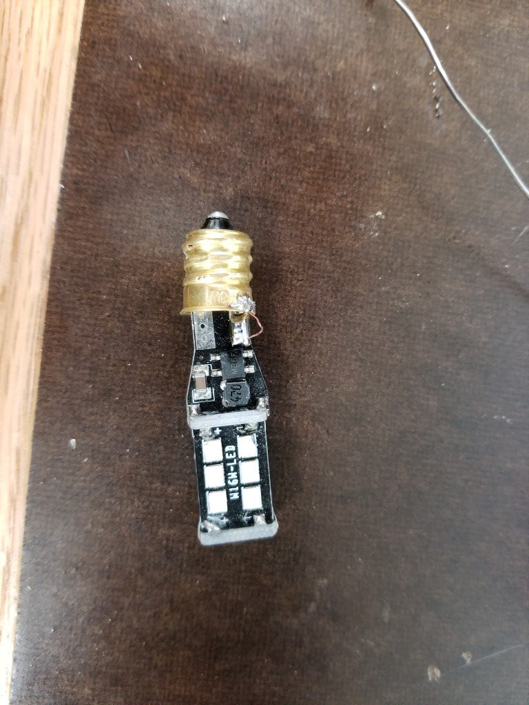
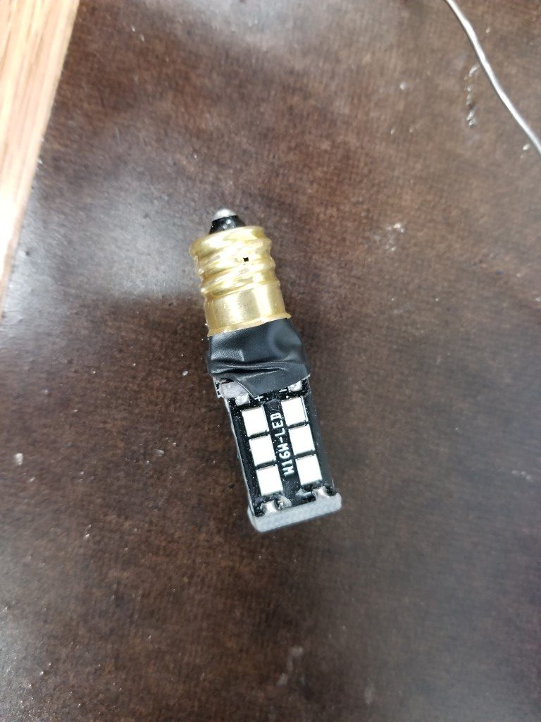
First I broke the original bulbs and chipped away the glass to leave only the base and wires. Next the wires were soldered to the LED bulbs, insulated with electrical tape, and the whole thing was pushed into the bulb base. The base was then filled with hot glue and the joint covered with heat shrink.
In the end I think they went together very nicely and since they’re LED they should last a lot longer while being brighter and draining the generator batteries less; best of all the whole setup cost less than the ‘proper’ replacement bulbs.
Troubleshooting “Space Age” Electronics
On the last few test drives the blinkers had begun blinking very fast. On many cars, even today, which use a thermal timer relay this would mean a bulb was burned out. The bus, however, uses a resistive/capactive timer circuit that’s relatively immune to such load changes. I opened up the ‘black box’ hazard/blinker control module and even though it only consists of a few relays, a pair of germanium transistors*, and a handful of discrete parts it’s by far the most sophisticated electronic part in the bus; actually it’s the only electronic part if no radio was installed.
*This was roughly the time frame when people discovered that silicon was nearly as good of a semiconductor but far cheaper and easier to work with.
Troubleshooting “Space Age” electronics like this is basically the same as troubleshooting modern electronics:
#1 – Replace any/all electrolytic capacitors.
#2 – If it doesn’t’ work, throw it away unless it’s really valuable and further in-depth analysis can be justified.
This repair was no different, though I had to guess at the values since the capacitor code/markings were non-standard and only decipherable to electrical engineers of 1960’s Germany. With new capacitors its back to blinking at a good rate for both blinkers and the hazard signal.

The clock also needed attention as it stopped a while back. Once I opened it up I found that everything appeared to be OK. I poked the rewind contacts with a pin while the clock was powered on and there was a small spark followed by a successful rewind; meaning the contacts were just dirty. After cleaning the contacts it successfully went through it’s usual automatic cycling. It’s a ‘normal’ old-fashioned wind-up clock in every way except that there’s a solenoid on a crank to rewind it and when the spring unwinds electrical contacts come together to energize the solenoid and rewind itself. Because it always has battery power available, the spring only lasts a minute or so before it cycles again.
Also, not pictured, I finished fabricating the passenger seat frame and added tabs to the seat mount. The seat pads arrived for both front seats; all seats are now complete and ready for covering in the spare vinyl that I have set aside.
Atlas/Craftsman Lathe Reversing Switch
Originally the Atlas/Craftsman lathes spun in only one direction; because of this they came with only an On/Off switch integrated into the lathe’s headstock. At some point in my lathe’s past the On/Off switch was removed and a reversing ‘drum switch’ added. The drum switch gives the flexibility to spin either directions for special uses (cutting metric threads, power tapping, etc) however it’s it’s too big to fit in the lathe’s headstock.
The previous owner had the switch mounted on a wooden arm extending up from the lathe’s workbench; re-using this idea would work but since I’ve moved the lathe to the shop countertop the arm would need to be rebuilt and I also don’t like the aesthetics or the need to reach over the spinning work to turn it on/off. Another option would have been to mount the switch under the lathe base, however for the carriage to clear the switch would require raising the lathe – it was already at a good working height and raising would effect stability/rigidity as well as being susceptible to dripping oil. Lastly, it could have been mounted just anywhere on the ‘outside’ of the lathe (on a guard door, past the tailstock, etc) – none of these locations seemed great and overall this just seemed like giving up.
So what I ended up doing over the past few nights was locating the switch in the only volume of space just big enough for it, under the motor. This location has the added benefit of making the wiring short and simple. As-is, this is of course very inconvenient, but I chose it with creating a linkage in mind. The addition of the linkage allows the original On/Off switch hole to be utilized (previously this was just an open hole), puts the control in a convenient place, and makes it look like it was designed this way. The linkage was a challenge and took a few iterations to get right. It consists of a 1/2″ OD steel tube that runs through the headstock, supported by two metal plates I fabricated. At the end of the tube I welded on a nut to accept a bolt that bolts on another arm I fabricated. The arm has a bolt welded through it that engages with a slotted lever welded to the drum switch’s lever. The resulting contraption actually works very smoothly: pushing IN runs the spindle forward, pulling OUT runs it reverse, and returning to center is Off. All that’s left to do is create a matching knob and mark/paint the switch plate.
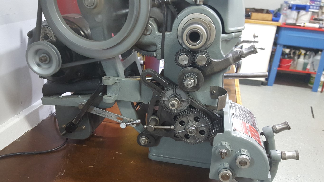
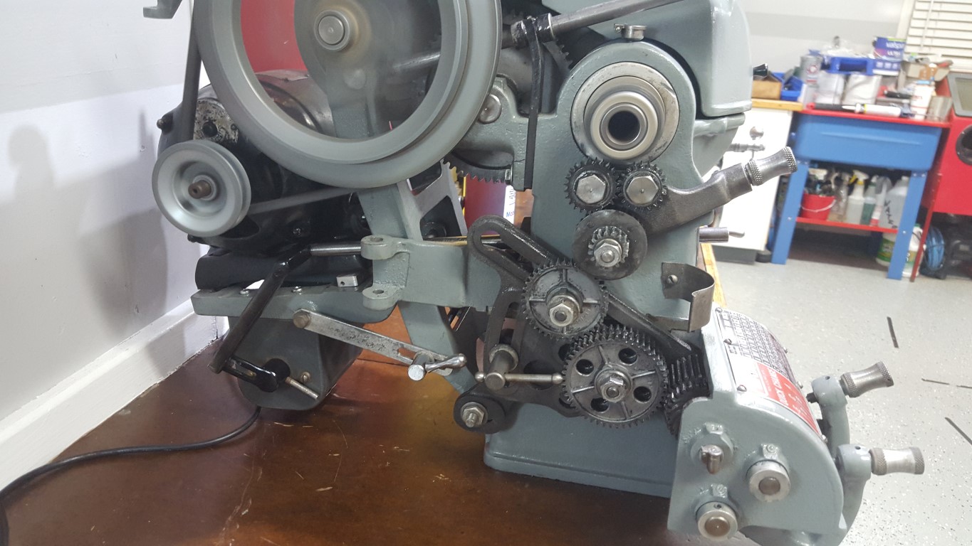

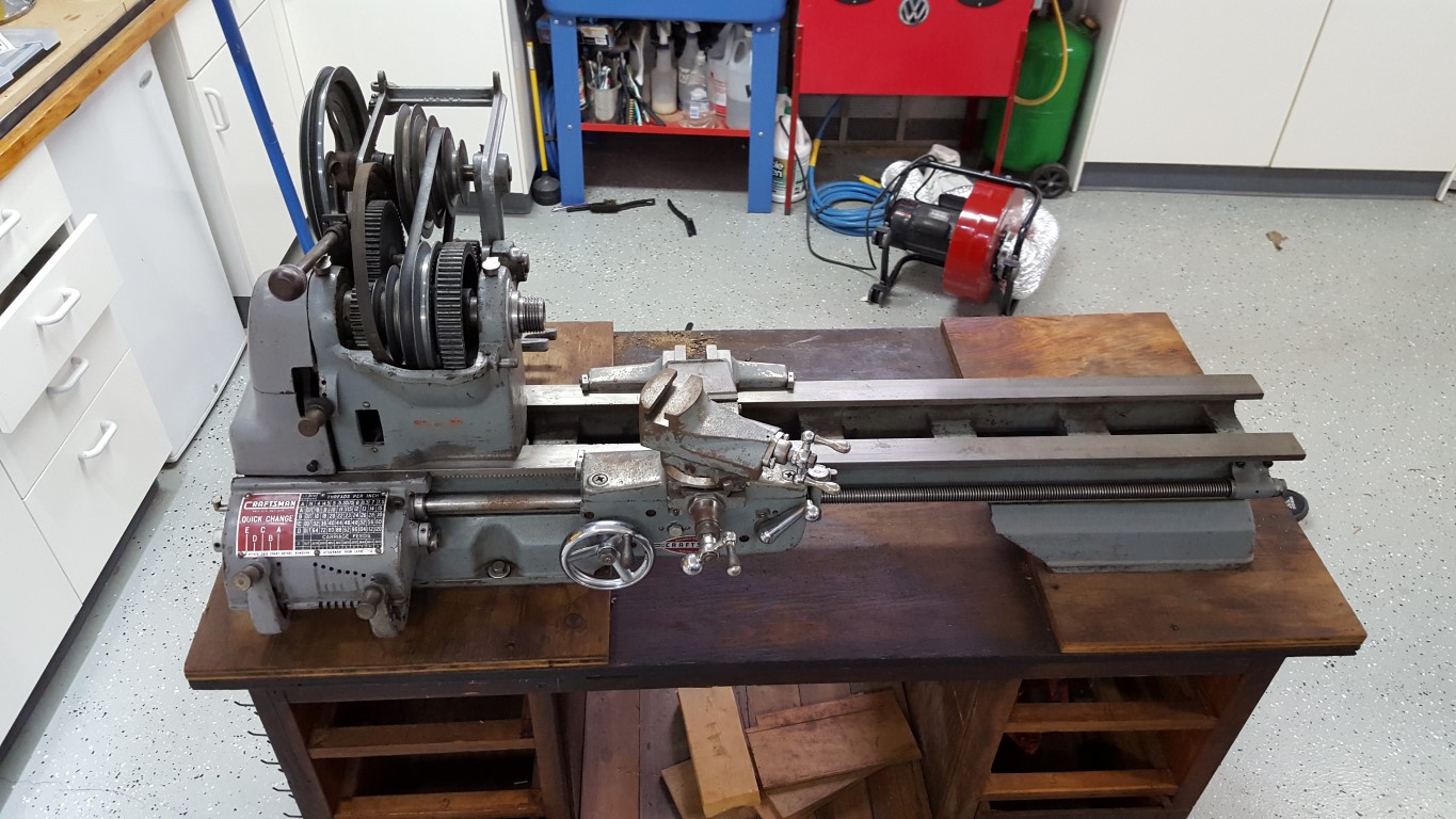
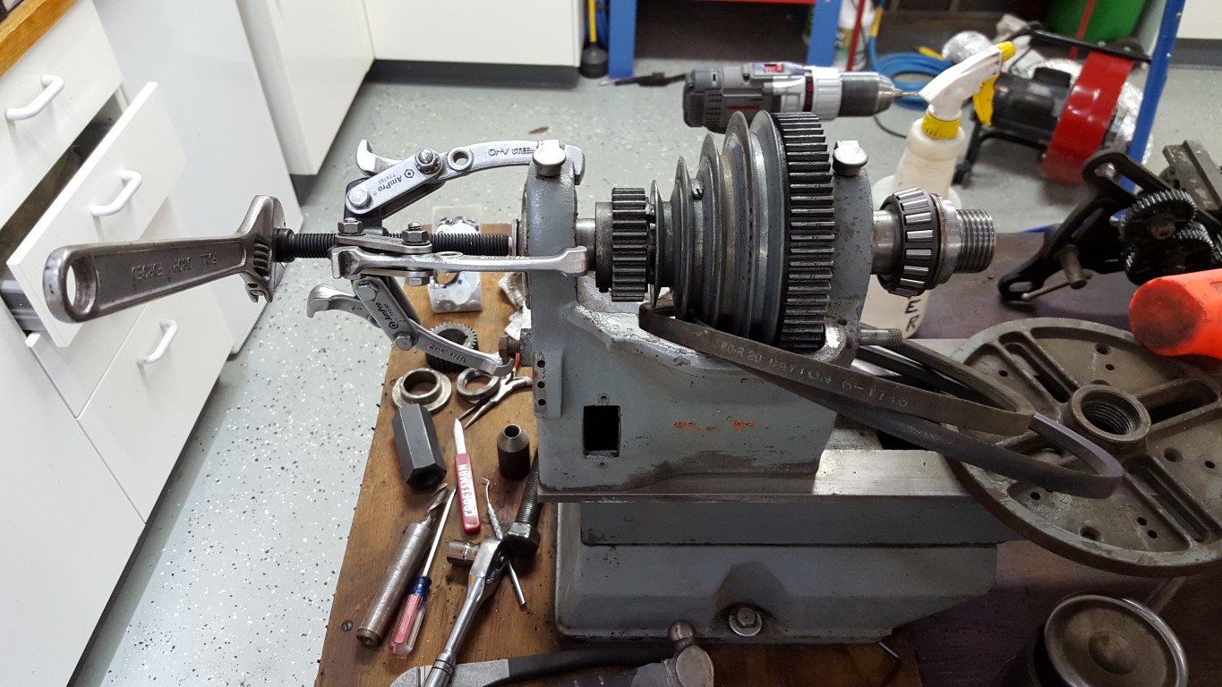
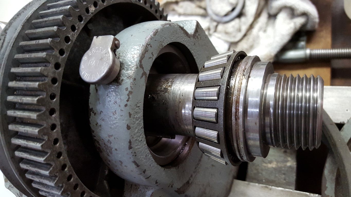
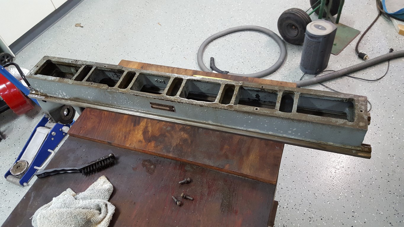
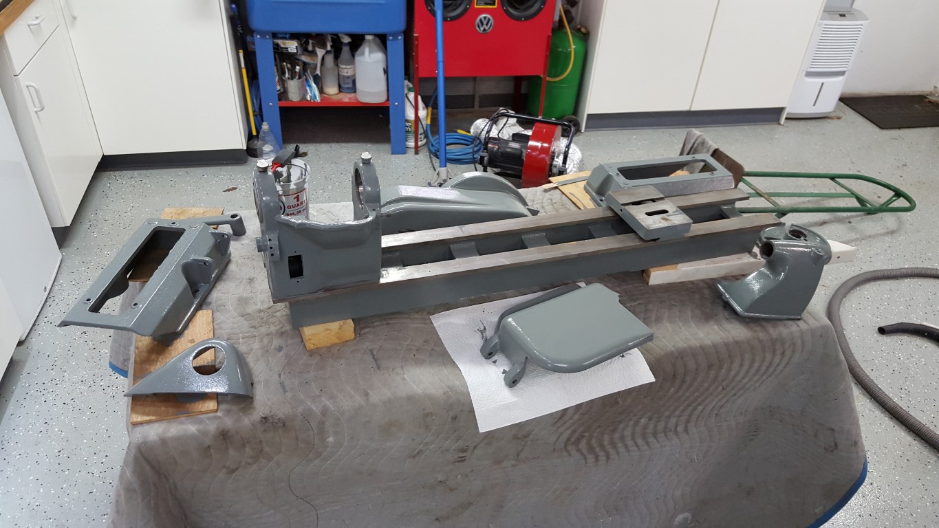
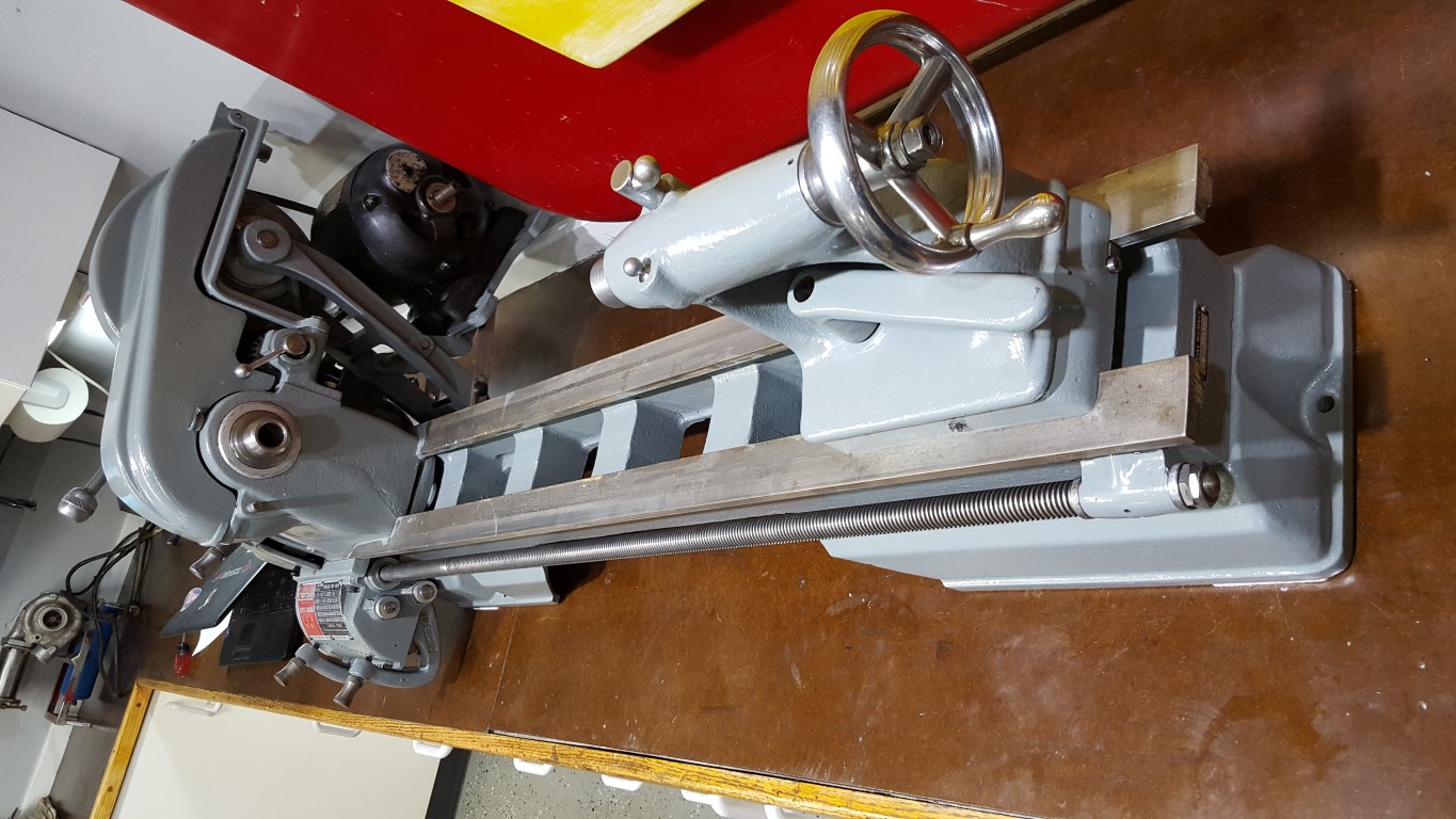
Atlas/Craftsman Metal Lathe
This winter I’ve done some much needed cleaning and painting of the garage; it’s survived the bus restoration and countless other small projects. This has put the jet engine project and bus transmission on hold, but I’m in no particular hurry with either.
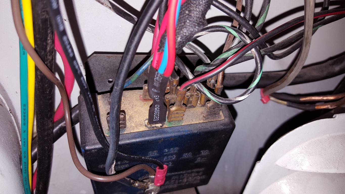
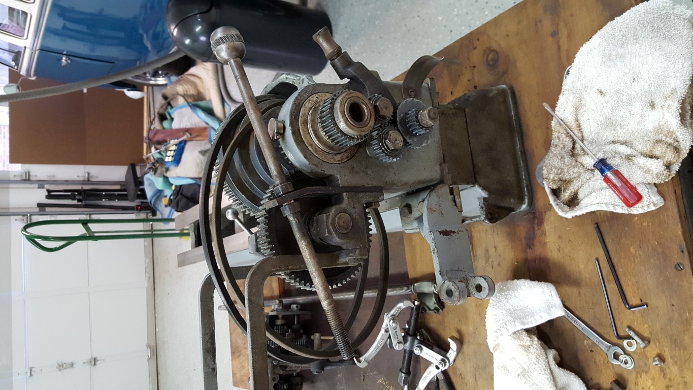
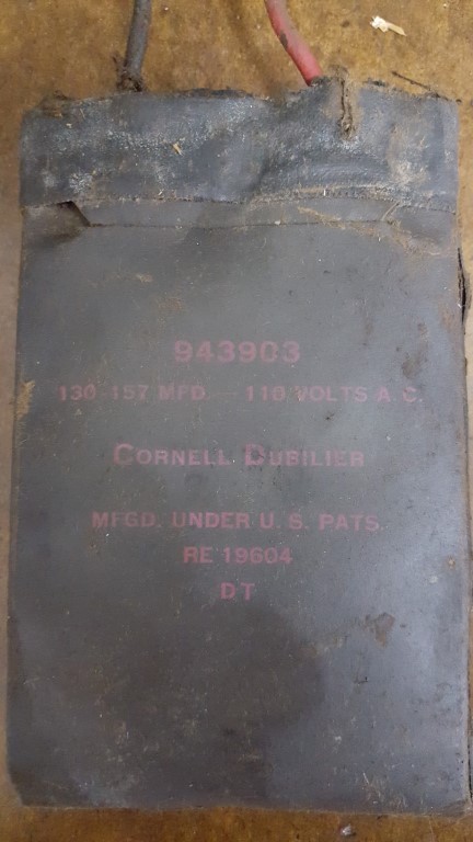
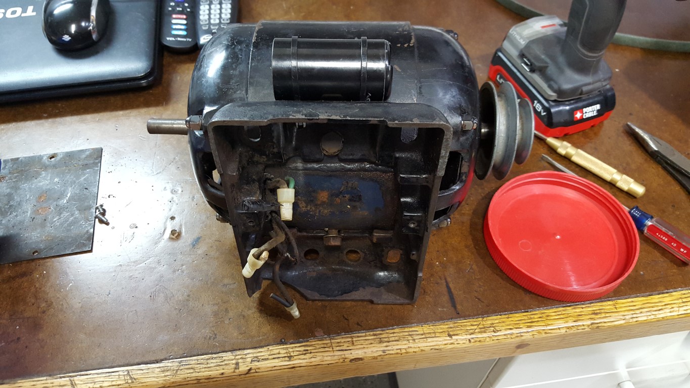
Also, recently I picked up an old Atlas (Craftsman) lathe I found on Craigslist with lots of tooling. This style of late was made by Atlas from the late 1930’s through the late 1950’s; based on the numbers engraved in this one’s bearings it seems to have been made around 1956. The manual that came with it was published in 1967; but I later found a receipt for the manual, proving that it was a replacement and explaining why the lathe in the manual looks like the late 1950’s through mid 1970’s version – both machines have all the same features and function the same though. For the most part it was in good shape and only needed some heavy cleaning, repainting, and a new motor capacitor; there are a few mechanical areas for repair/improvement that I will tackle, but nothing that prevents it from operating now. The original motor used a flat capacitor that’s no longer made in it’s motor base, so I had to get a little creative with mounting the replacement on the side of the motor.
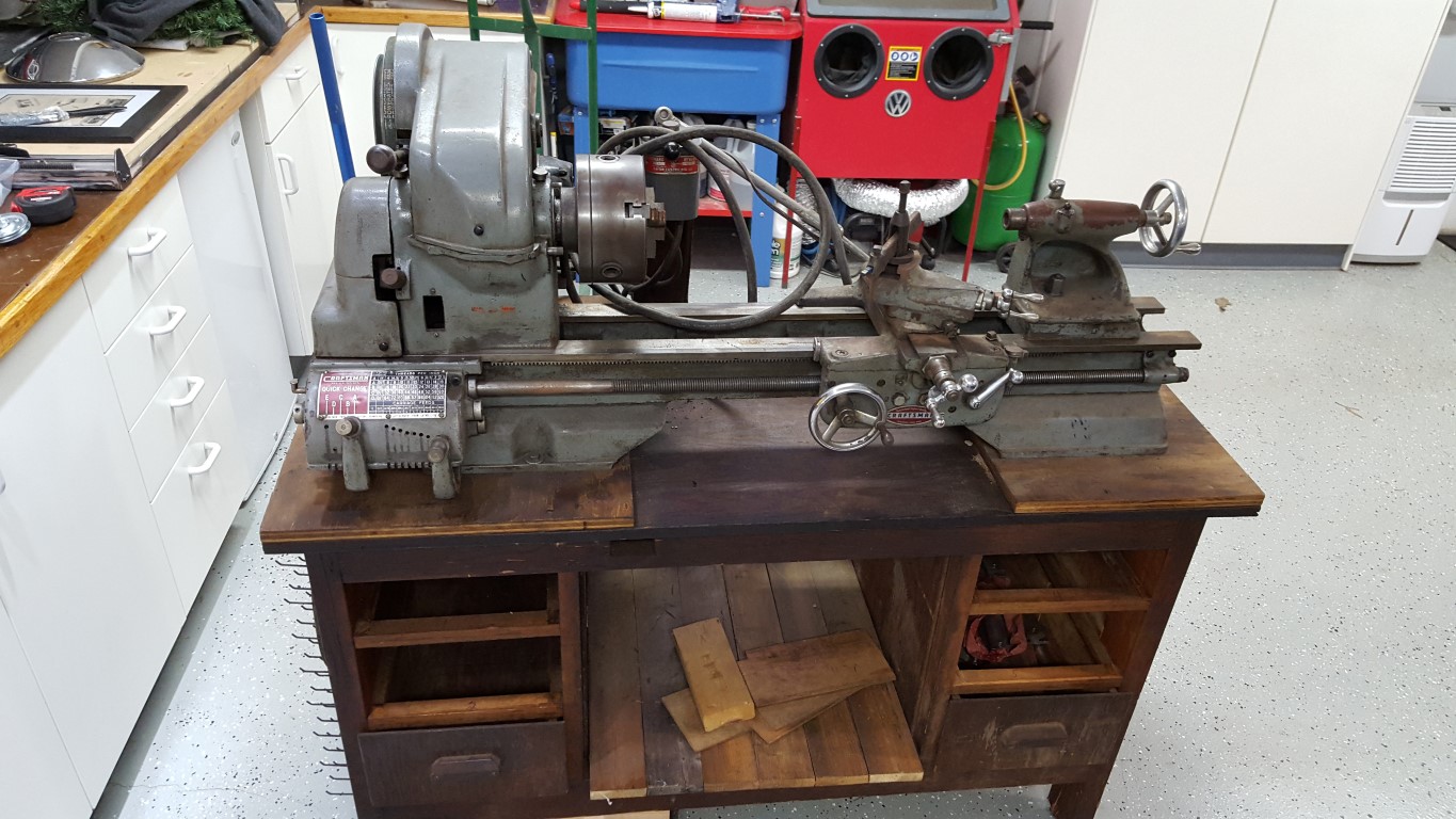


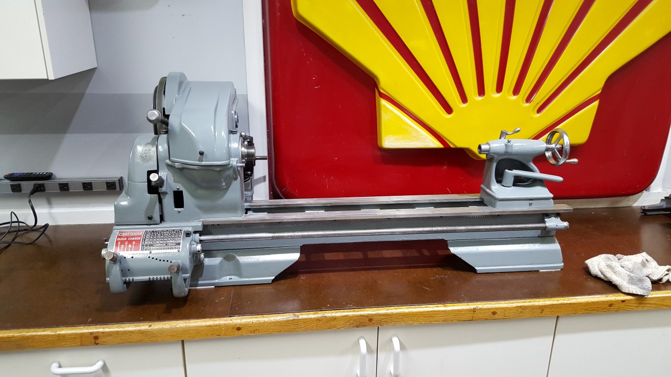
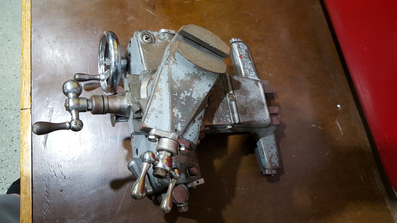
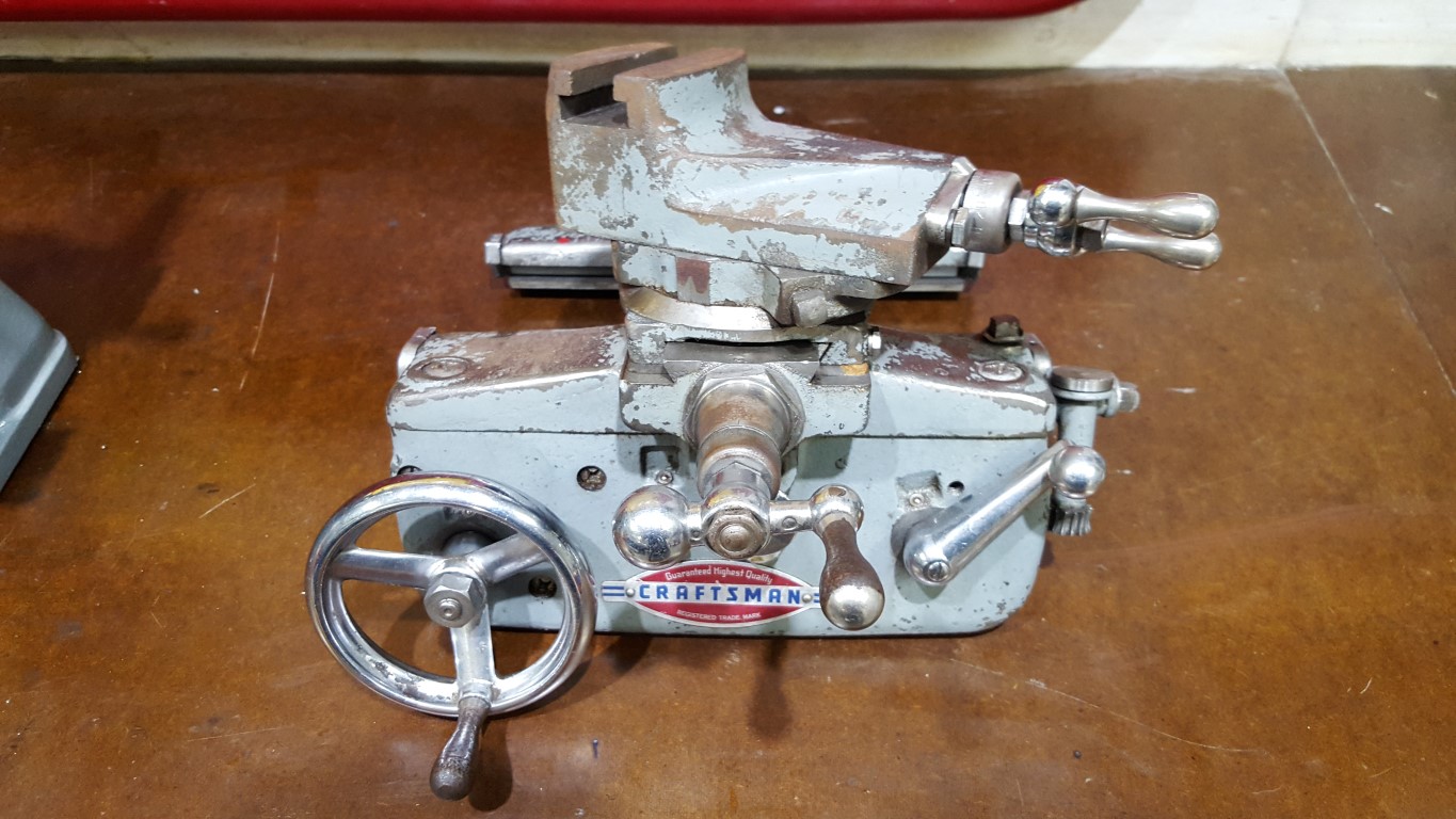
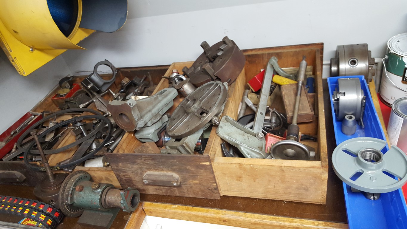
No particular project in mind for this, but no doubt it will come in handy with other projects especially since it has the milling attachment allowing it to serve as a small mill as well.
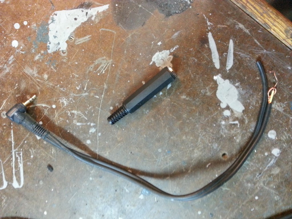
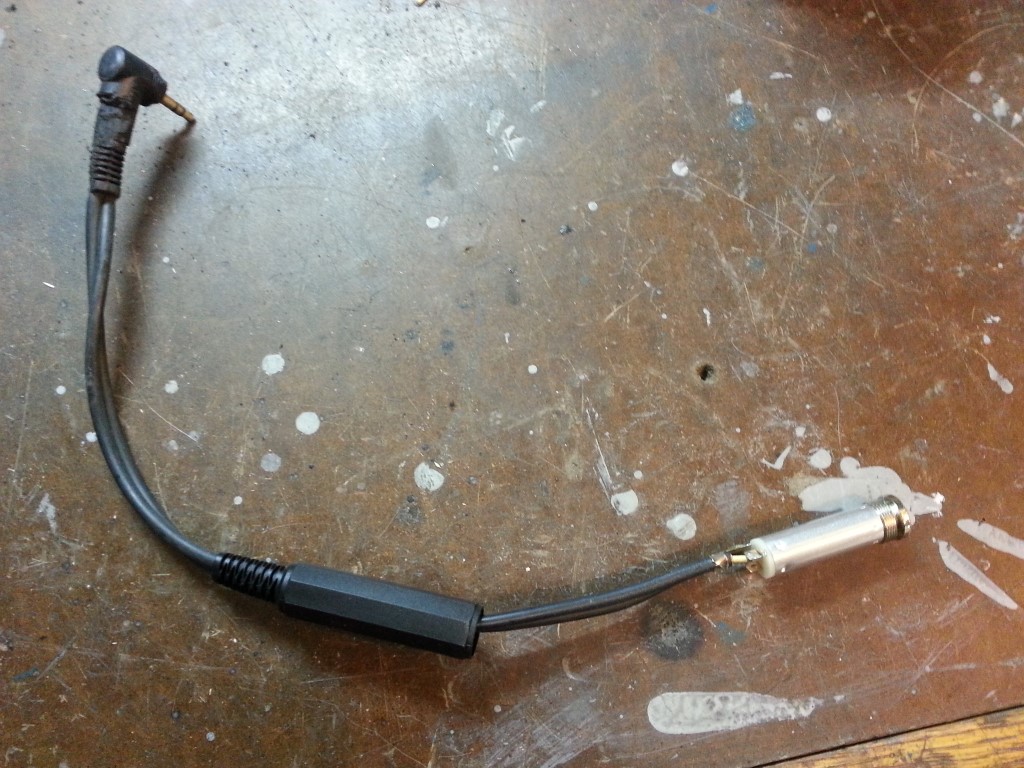
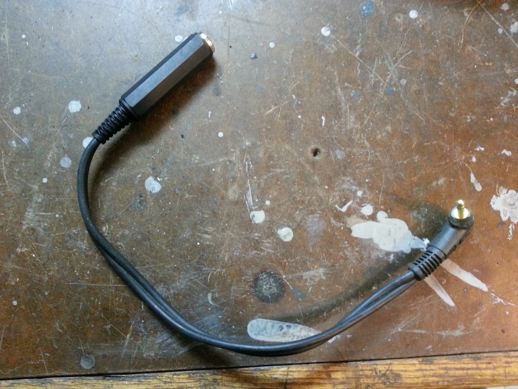
Using a Real Aviation Headset with a PC Simulator
In parallel with real-world flight training I’ve begun to use a PC flight simulator more seriously. This reinforces what’s learned in the real plane and also allows me to practice flights ahead of time. The simulator is only vaguely analogous to real flying though, so the more I can do to make it realistic the better. One realism point would be to use the real aviation headset, but the headset does not directly plug into the PC. After a good bit of research cross-referencing part numbers and checking schematics, I came to two critical conclusions:
#1 – Standard 1/4″ mono audio dimensions are the same as general aviation headset plug dimensions. (The speaker plug, not the microphone plug)
#2 – The sound card output levels are compatible with the headset’s required input level. (not so low that they’d be inaudible, and not so high that they’d blow out the speakers on even the lowest setting)
Once those realizations were made it was easy enough to make an adapter cable from a scrap audio cord and a $2 1/4″ mono jack. There are ready-made adapters online, but these go for far more then even the standard 5X markup for anything with ‘aviation’ in the description; so it was worth the effort to spend a few minutes and build myself. The microphone connector is more special-purpose and would require finding the special jack and likely some circuitry to make the levels work for the PC mic input, I don’t do anything in the simulator that requires the microphone though, so that connection just stays unplugged.


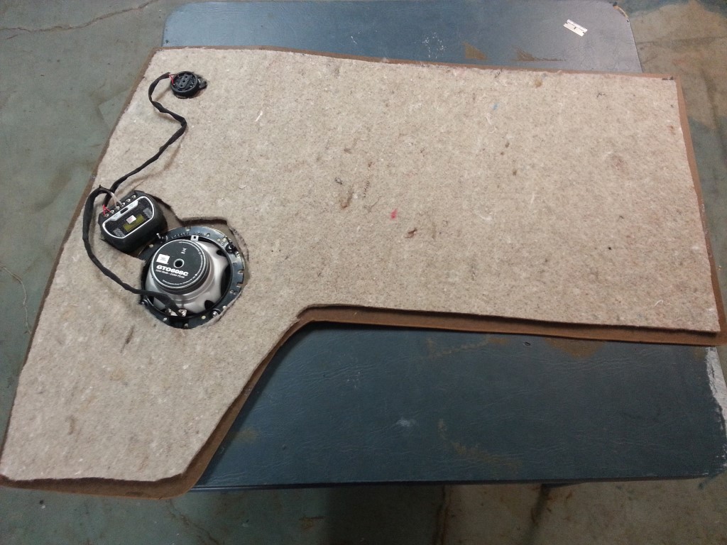
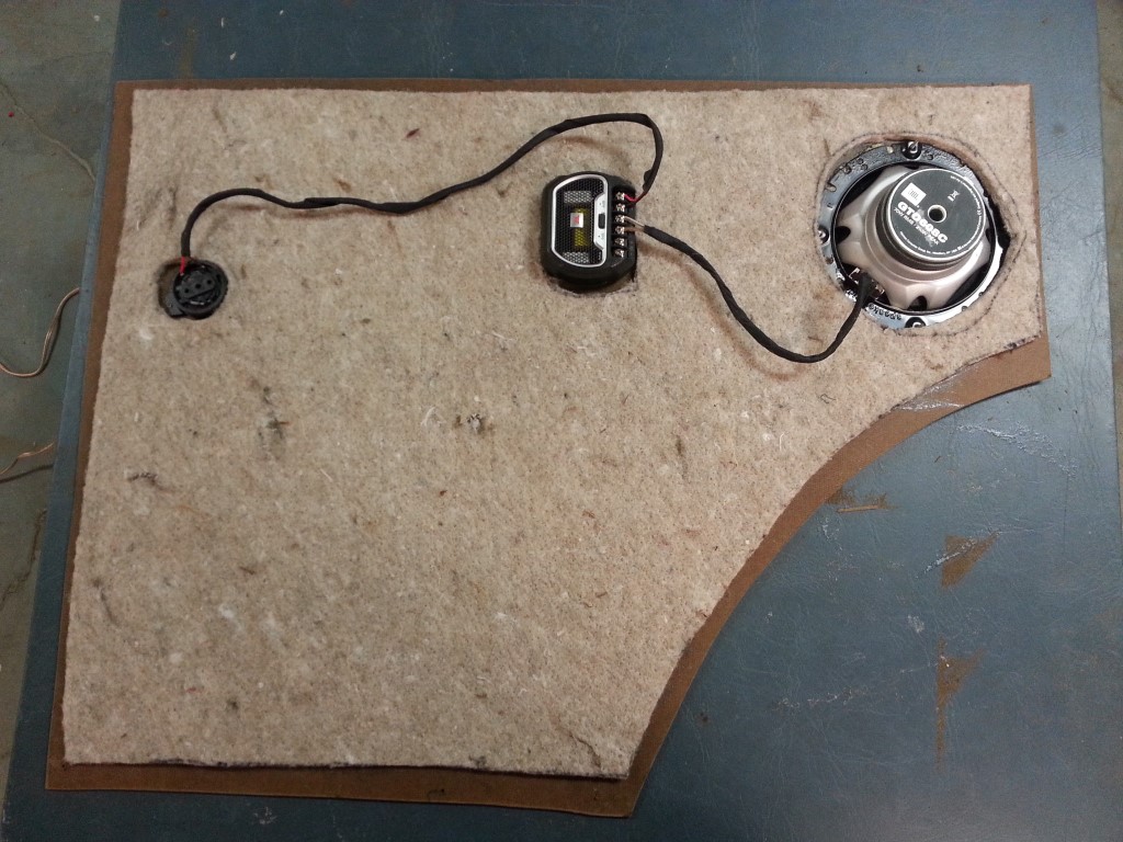
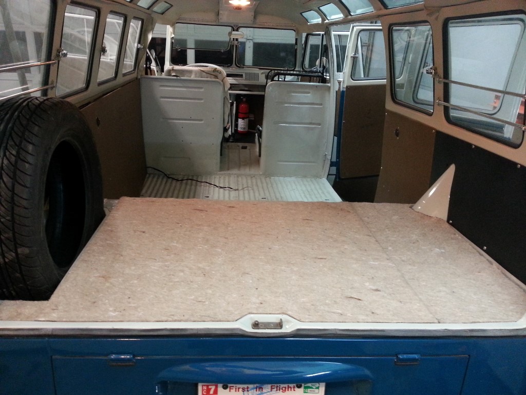
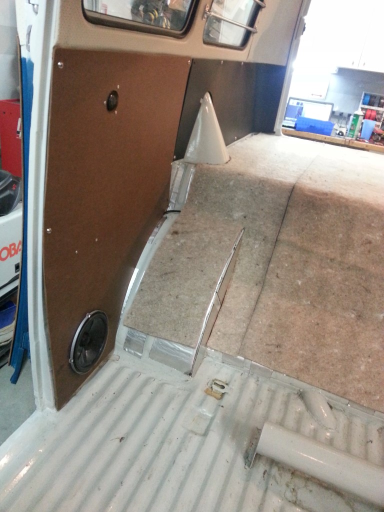
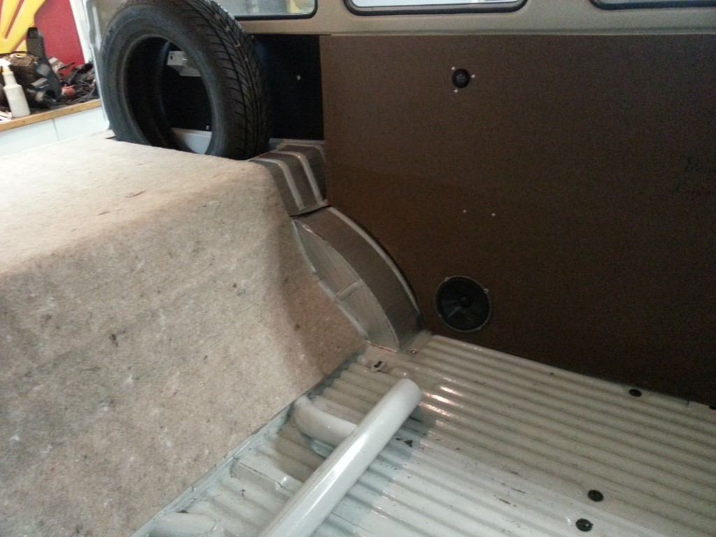
Interior Insulation & More Speakers
Since I’m again waiting on engine components, tonight I insulated the interior panels with jute insulation and added speakers to the rear interior panels. The rear speakers are lower than I’d like, but the bottom of the wall cavity is the only place thick enough (barely) to allow the speakers to sit mostly flush with the interior panel. I’ll be making era-appropriate covers for all 4 of the larger speakers that should provide some protection.