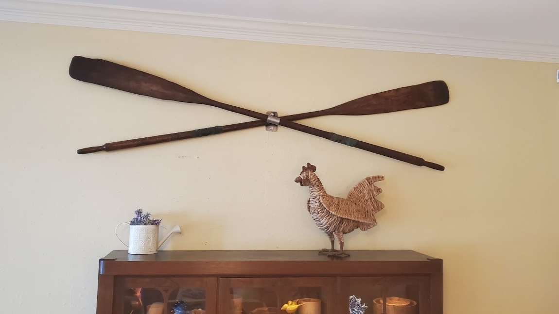
Crossed Oar Wall Mount
Quick project to mount some oars on a wall for decoration. It looks like the ‘normal’ way of doing this involves leather straps, brackets, spacers, etc. It gets messy relatively quickly and seemed like a lot to align/mount on the wall.I also wanted to leave the oars unmodified, so to avoid all these problems I made a custom steel mount. I first made a mock-up in CAD.
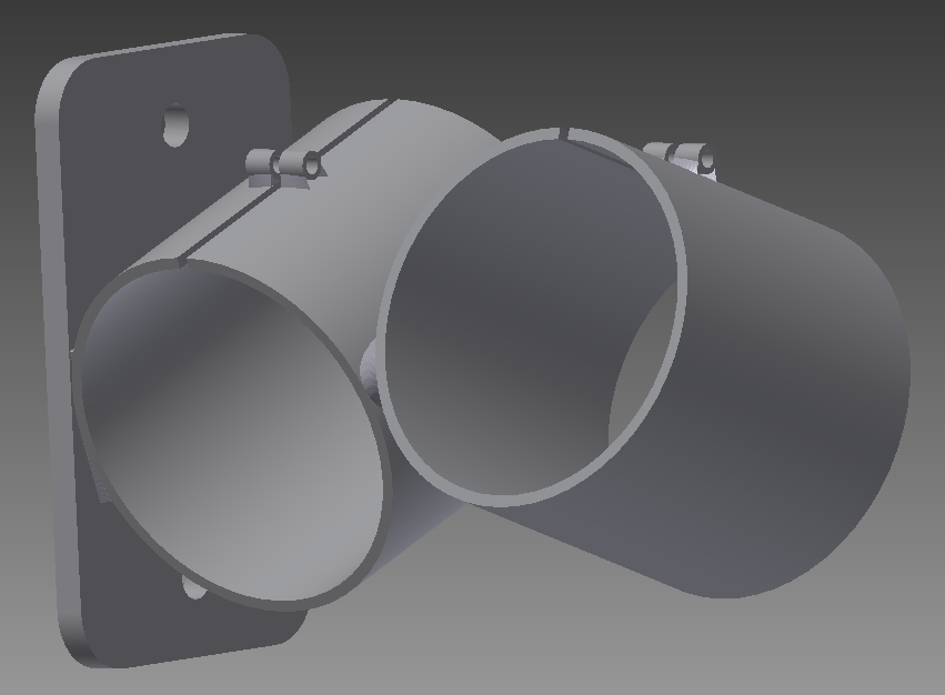
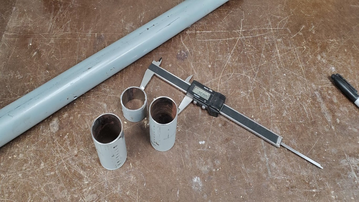
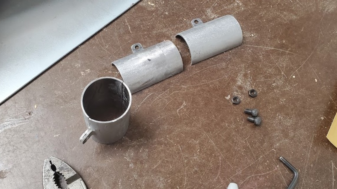
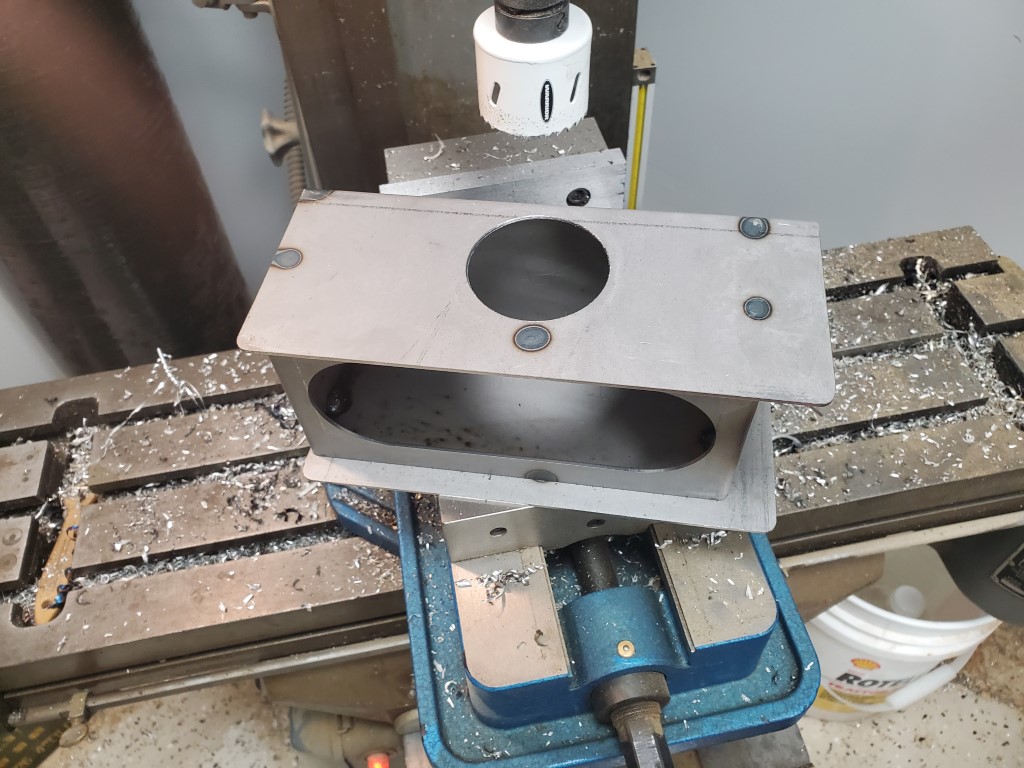
Next I found some steel tubing on the scrap pile that was the right size, cut it to length, and then cut a slot and welded on some tabs for a pinch bolt. The plan was to slide the tube over the handle side of the oar to the middle then tighten the bolt to clamp the oar in place. This didn’t work, because even though it’s not readily visible, the oars have a ~1/4″ taper from the handle end to the center. I had measured the center when sizing the tube, so it wouldn’t fit over the handle. I didn’t want the tube any bigger because it would look odd/oversized in place, so I began making a hinge that would allow the tube to flip open for installation. This effort failed, the tiny bit wandered in the long rod; hinge alignment wasn’t going to work. I then realized that the pinch bolt alone was strong enough to hold the tube halves together and abandoned the hinge idea – if it did need the strength, a bolt on either side would be much simpler.
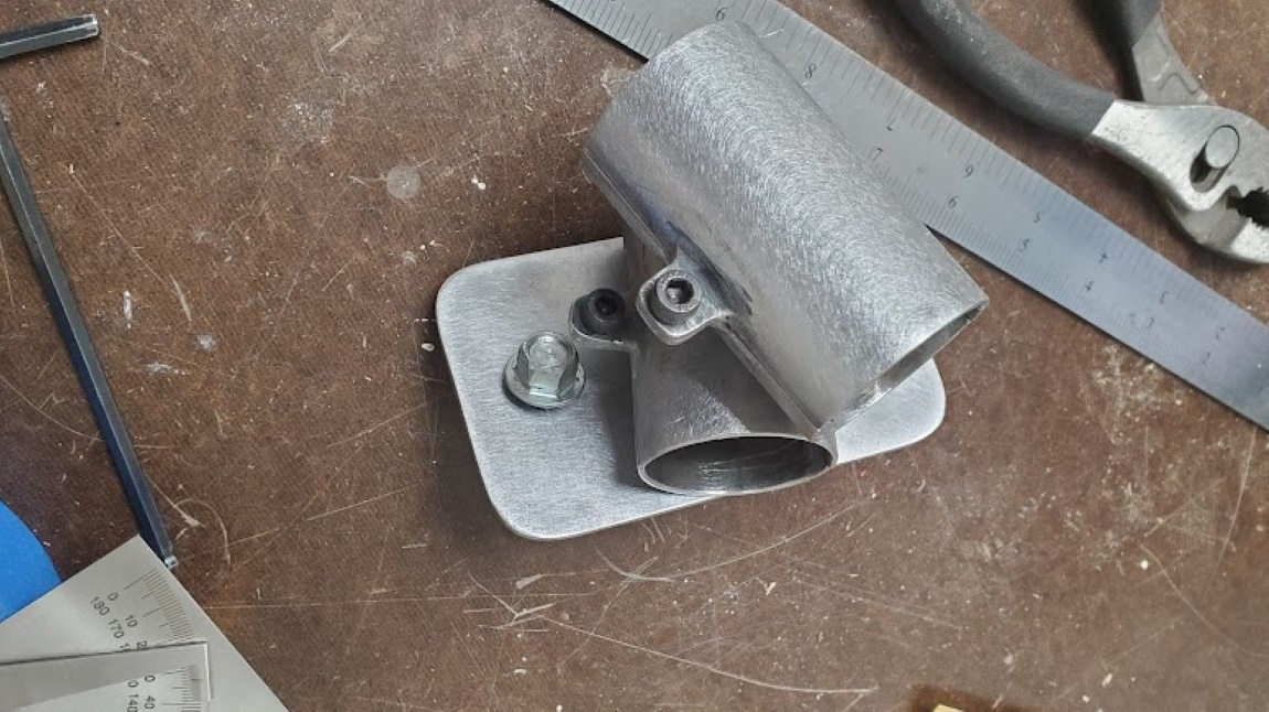
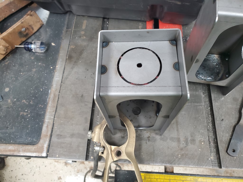
I then made a mounting plate and drilled a hole in its center and the center of 3 of the 4 tube halves. This hole allowed everything to be bolted together temporarily and aligned prior to welding. It was then welded together, cleaned, and tested. The base was lag bolted into a stud.
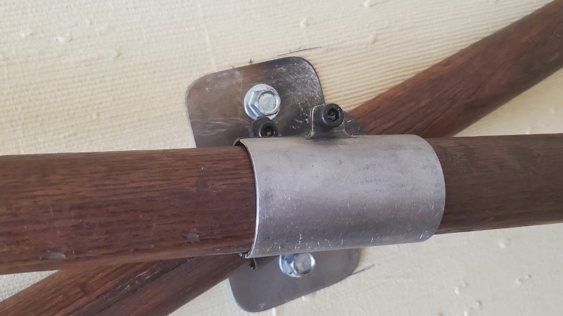
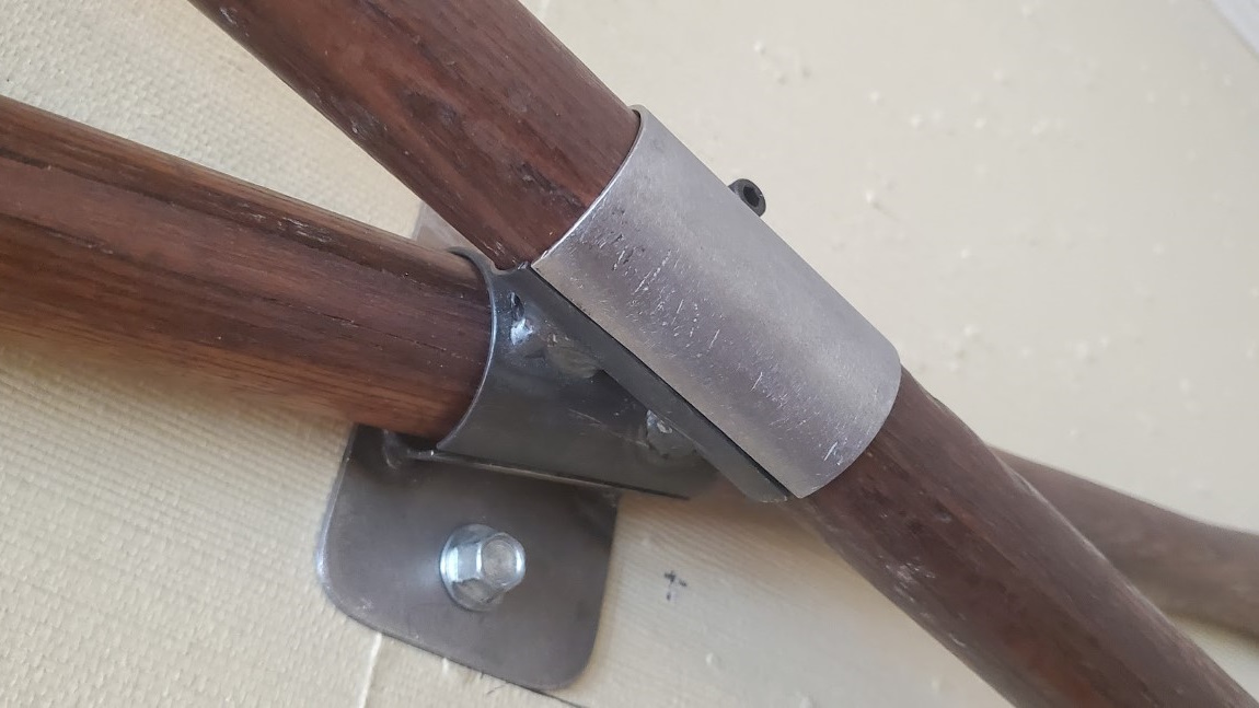
All that’s left is to take it down and finish the mount – I will likely use a metal black solution and oil for a natural metal look. The inside of the tube shells will also get a layer of felt to hold the oars securely (The tube size left just enough gap to account for this)
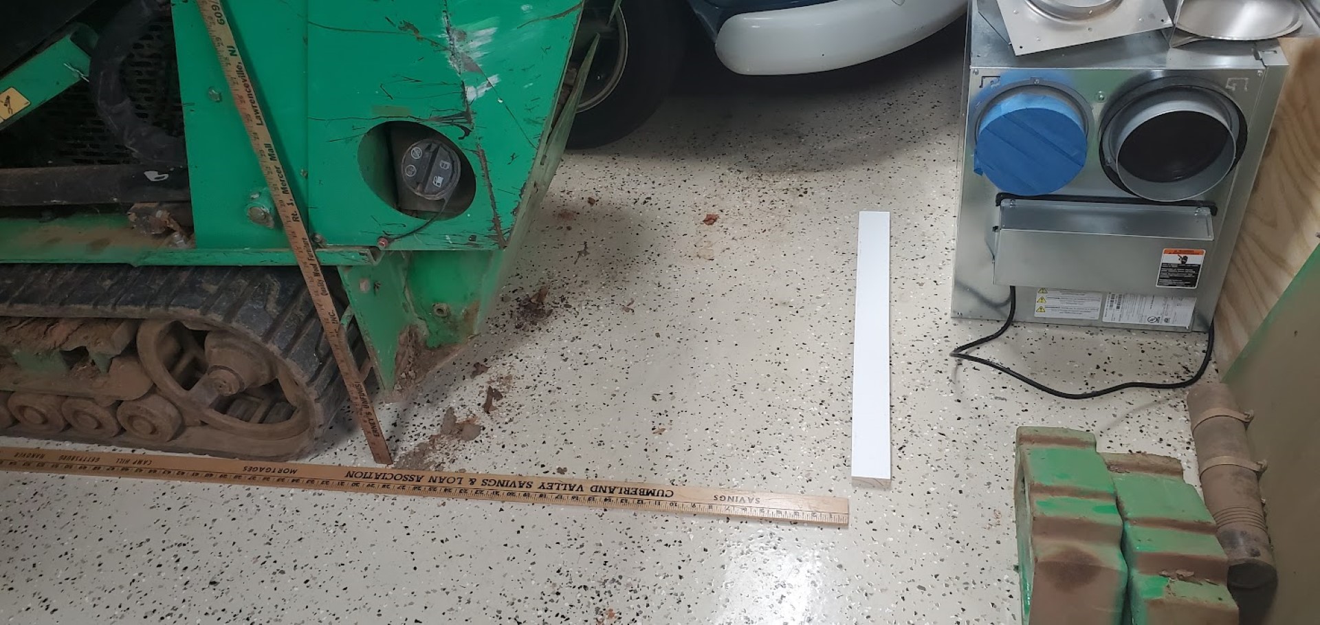
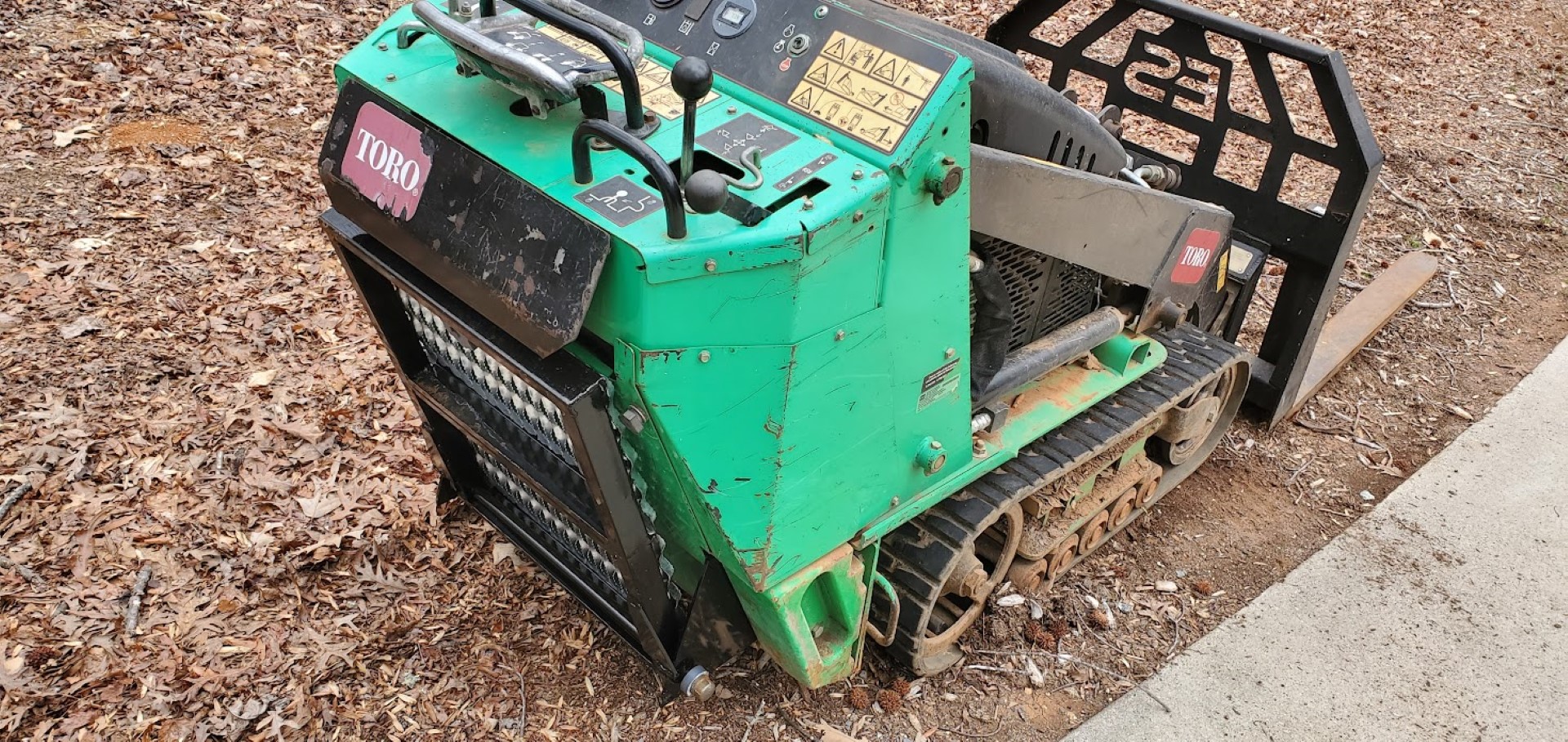
Toro Dingo Platform
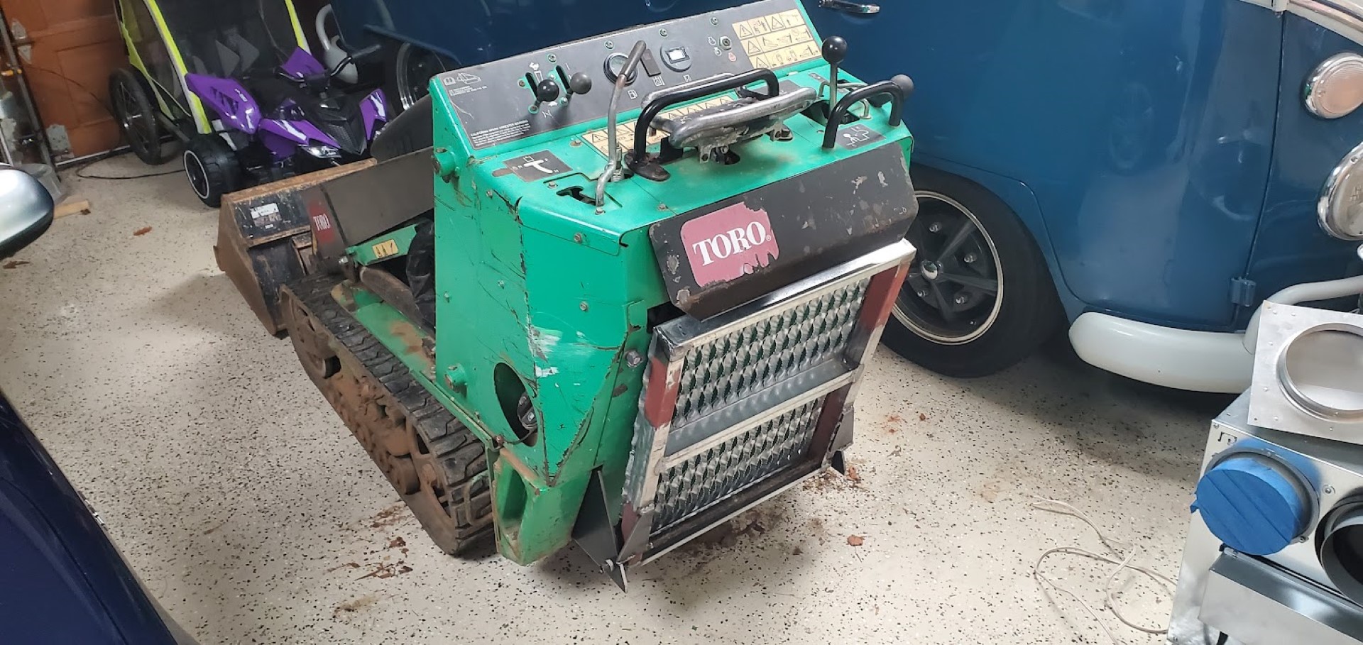
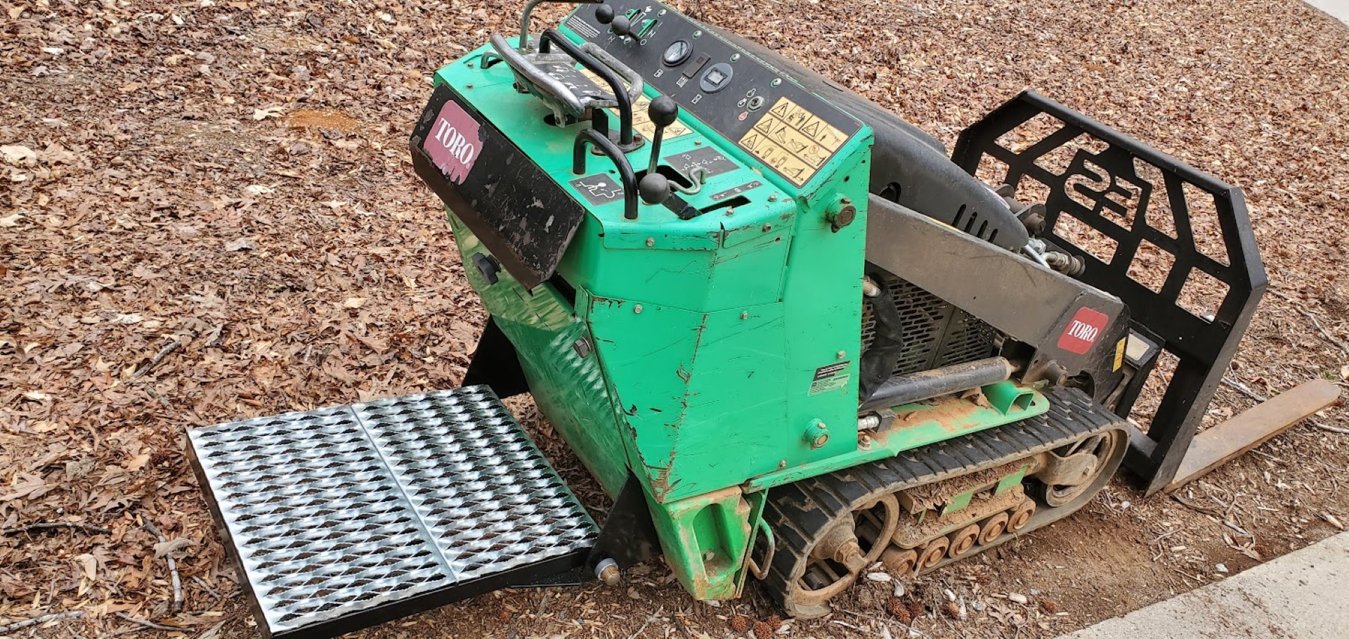
Last spring I won an auction for a Toro Dingo TX427 mini skid steer. Uncharacteristic of my usual equipment purchases, it didn’t need anything other than cleaning and an oil change. It came with the standard bucket, and I also later got a pallet fork attachment and a tooth bar for the bucket. Over the last year it’s been extremely useful with various landscaping tasks, as well as moving around pallets of materials for various projects. Mostly though it’s the perfect tool for dealing with downed trees and getting logs to the sawmill or burn pile.
One limitation that became apparent is the machine’s limited counterweight – the back begins to lift well before the hydraulic pressure relief trips. An optional feature from Toro addressed this problem by adding an operator platform, but mine lacked this option. I’d kept an eye out for used Toro platforms, but they weren’t often available and were overpriced – especially after considering shipping. A simplified aftermarket version was available closer to when the machines were new, but these had stopped production.
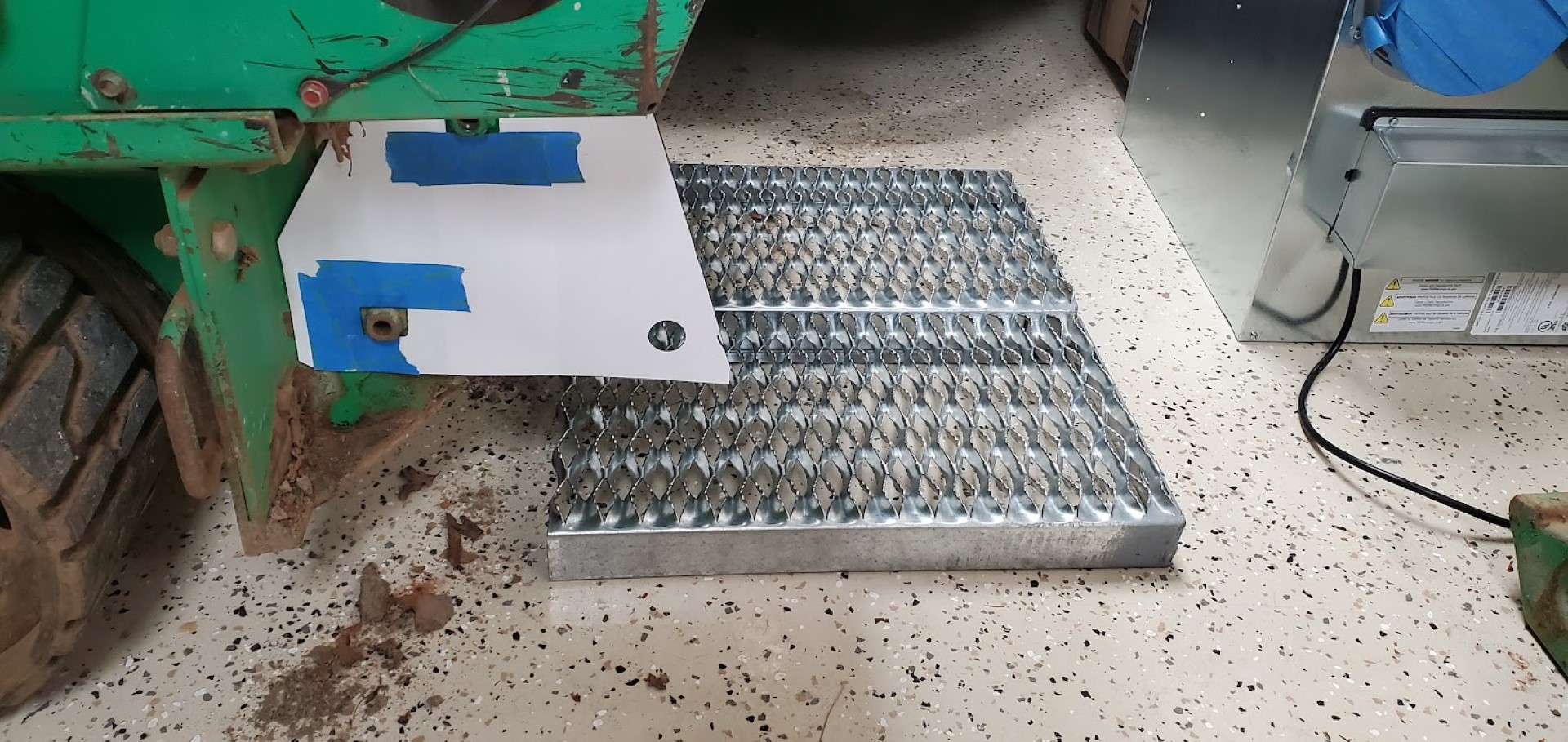
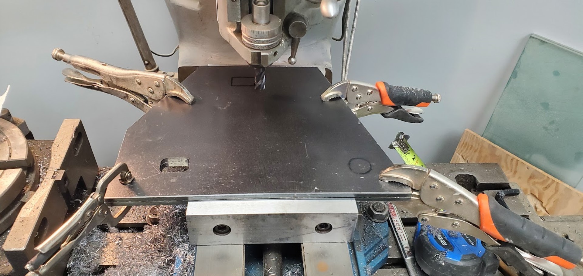
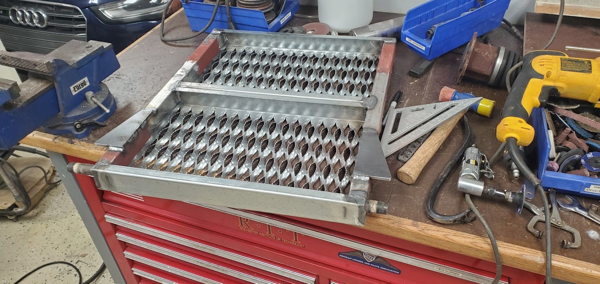
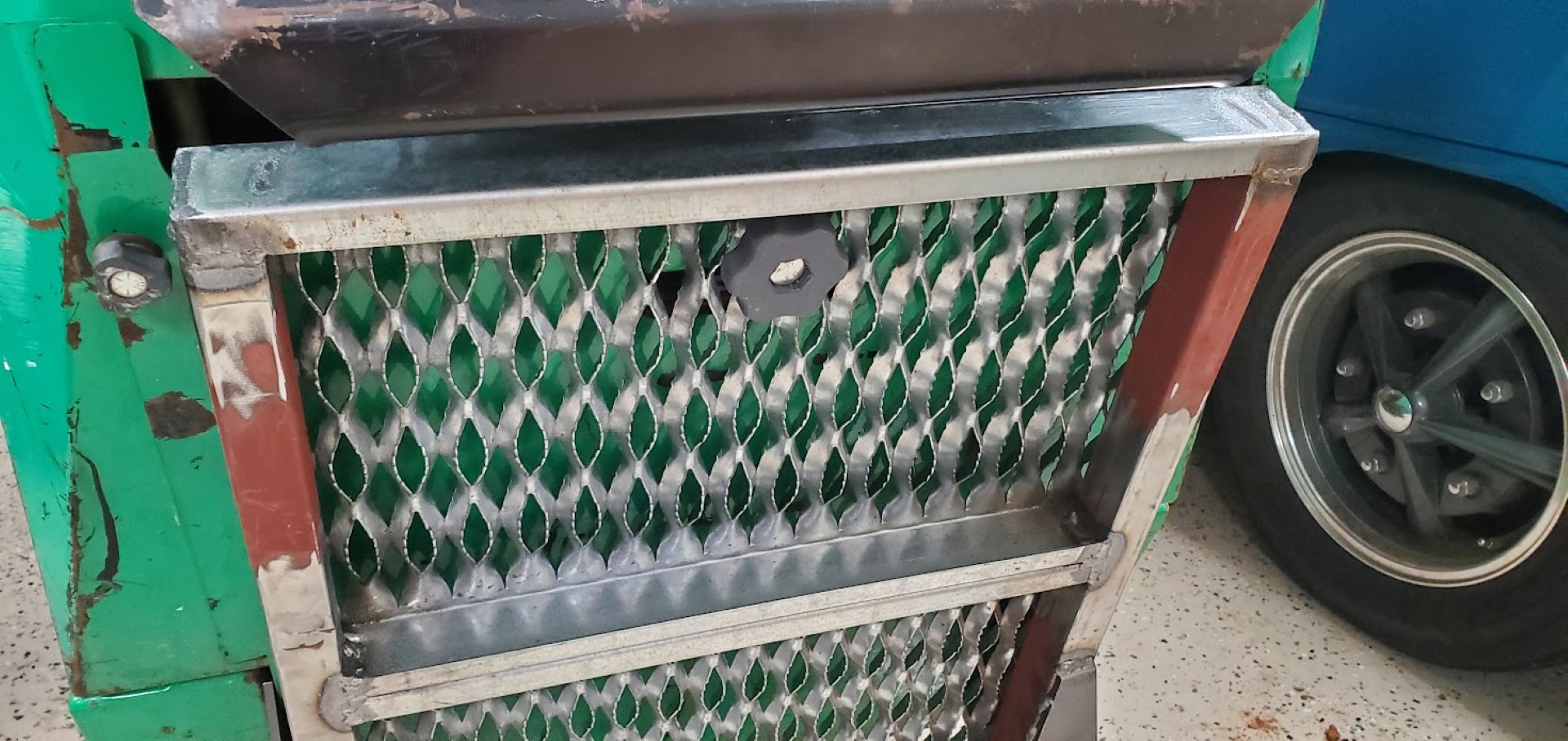
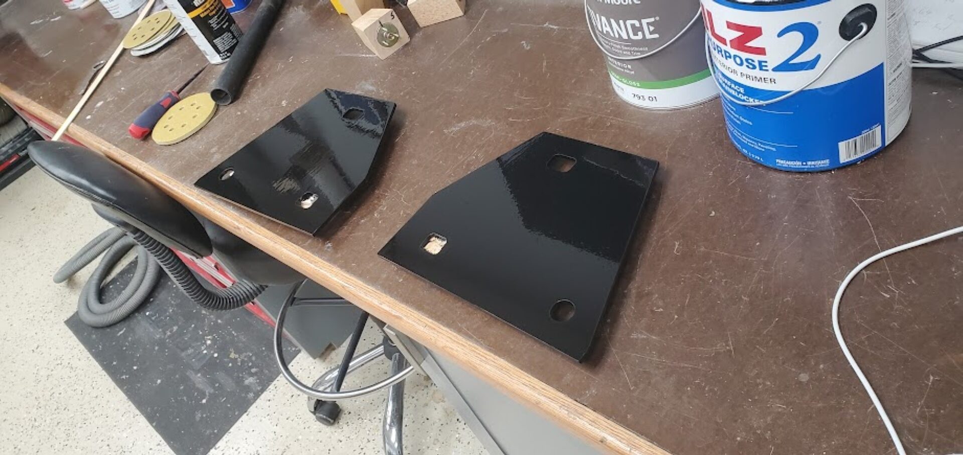
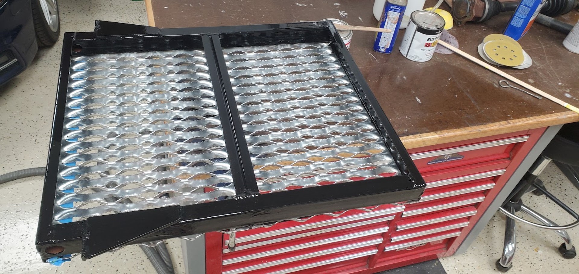
With that considered I decided to build my own platform based on pictures of the aftermarket version. It consists mainly of an expanded metal stair tread cut in half and welded back together into a square. Two square tubes reinforce the stair tread, and then it all hinges on a length of black iron pipe that runs through brackets sandwiched between the frame and the existing counterweights. Stops were then welded on each side of the platform to hold it level when deployed. When folded up against the back of the machine, a bolt (with 3d printed knob handle) holds it all in place. It’s flat enough when folder to not be in the way for operating while standing on the ground.
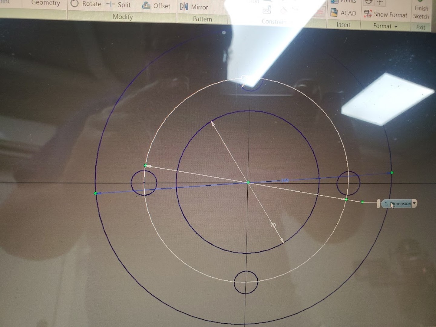
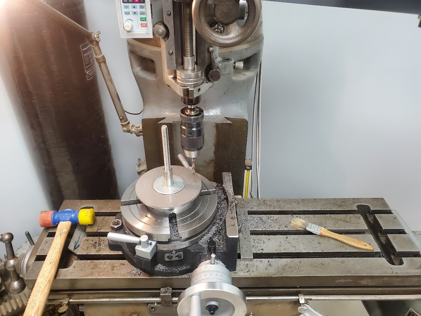
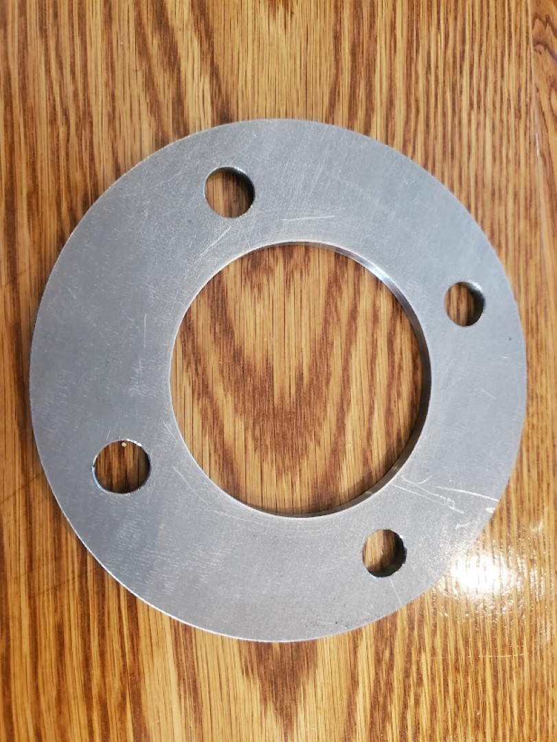
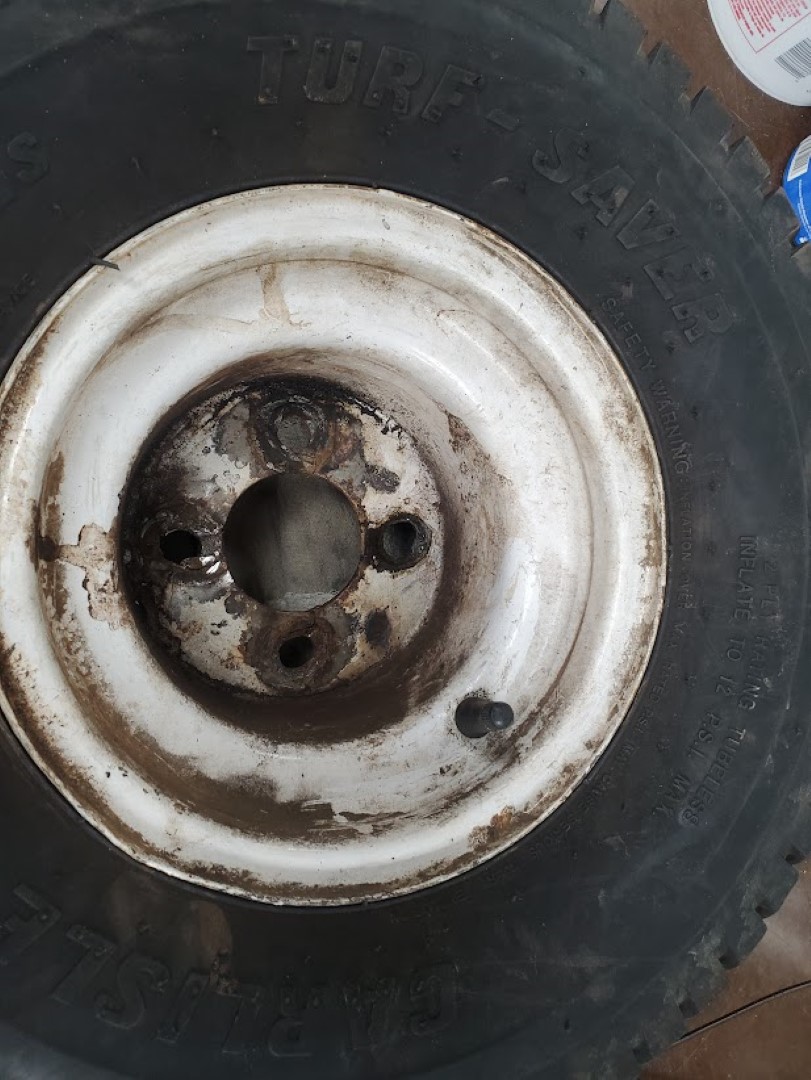
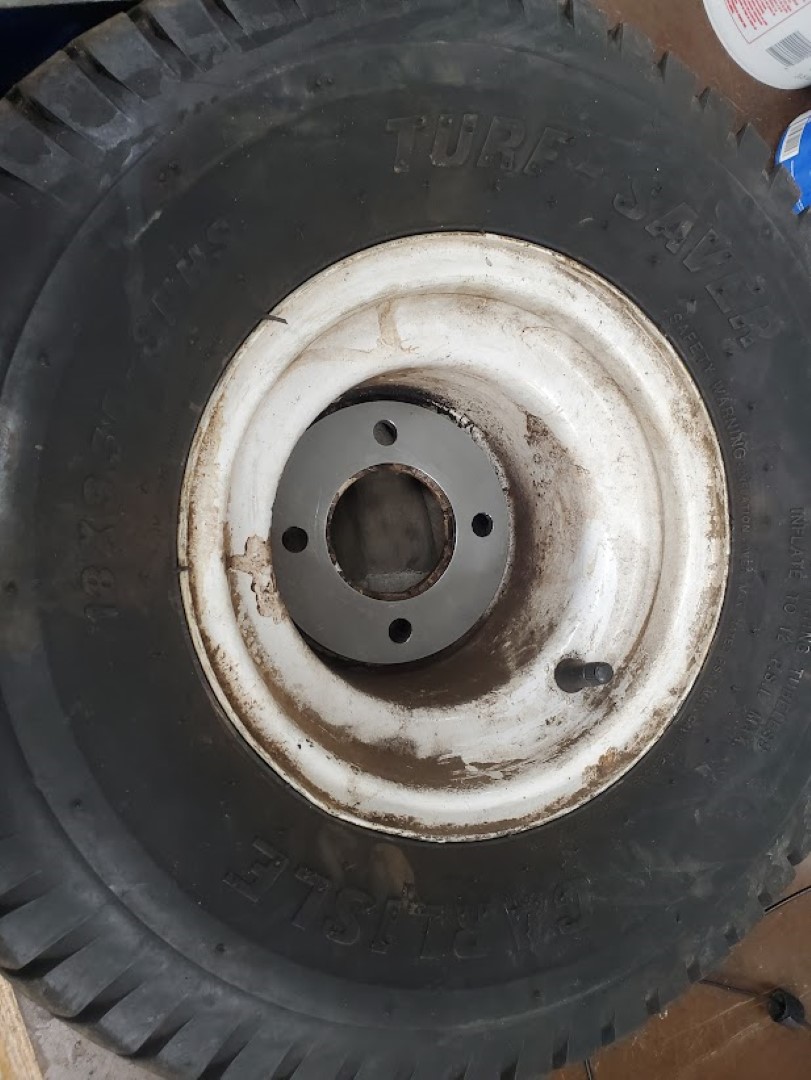
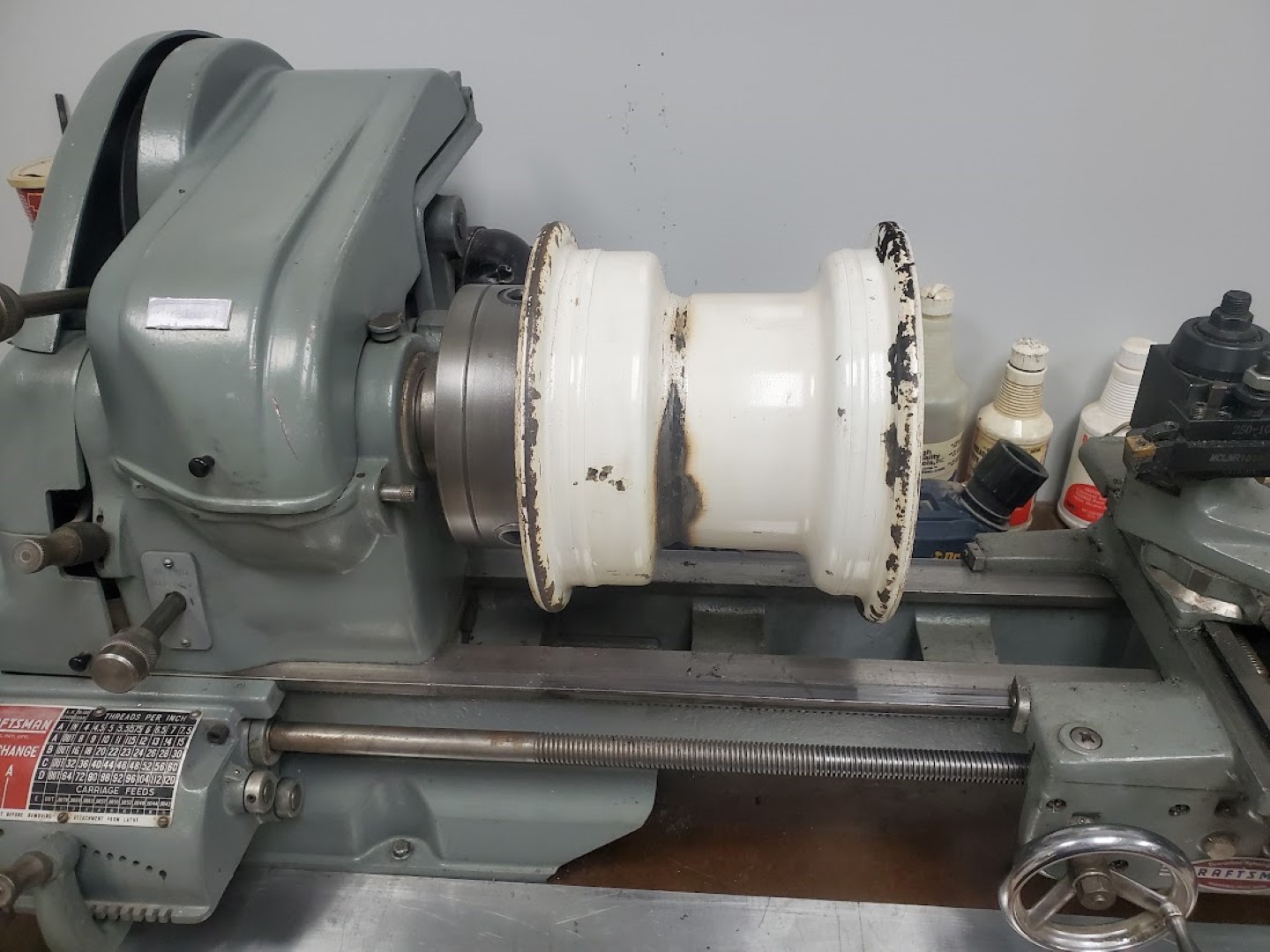
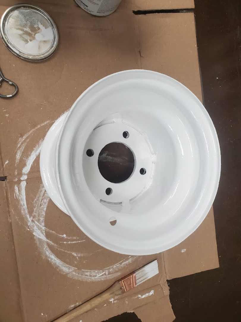
Kubota F2000 Wheel Rebuild
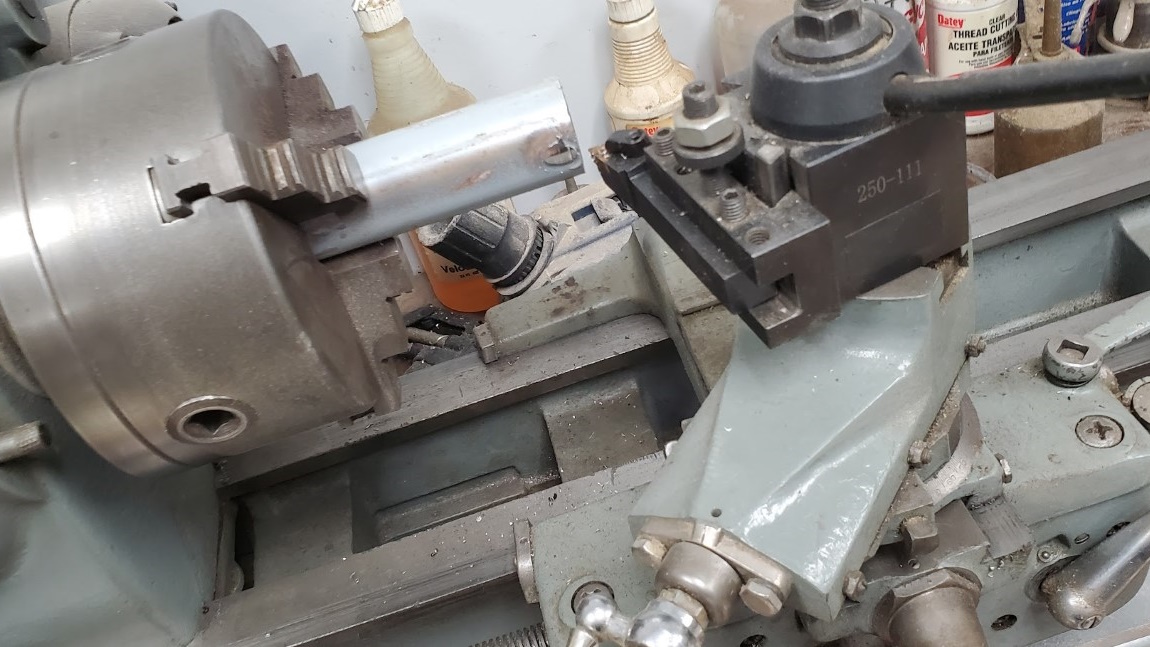
Recently one of the wheels on the mower broke. This hub of this particular wheel has always been a weak point and I’ve welded it back at least once. This time it was too far gone though and I intended to replace it… that is until I realized this wheel is a very odd size and offset that’s specific to this series of mowers. It wasn’t clear that replacements were obtainable. With that being the case I decided to machine a new flange that could be welded in place to reinforce the inner wheel. The flange consisted of a 1/4″ steel plate turned down to the right diameter, then center bored and hole pattern drilled on the rotary table. The flange was then welded in the wheel and the back side faced on the lathe to ensure the face of the wheel would be perpendicular to the axle hub.
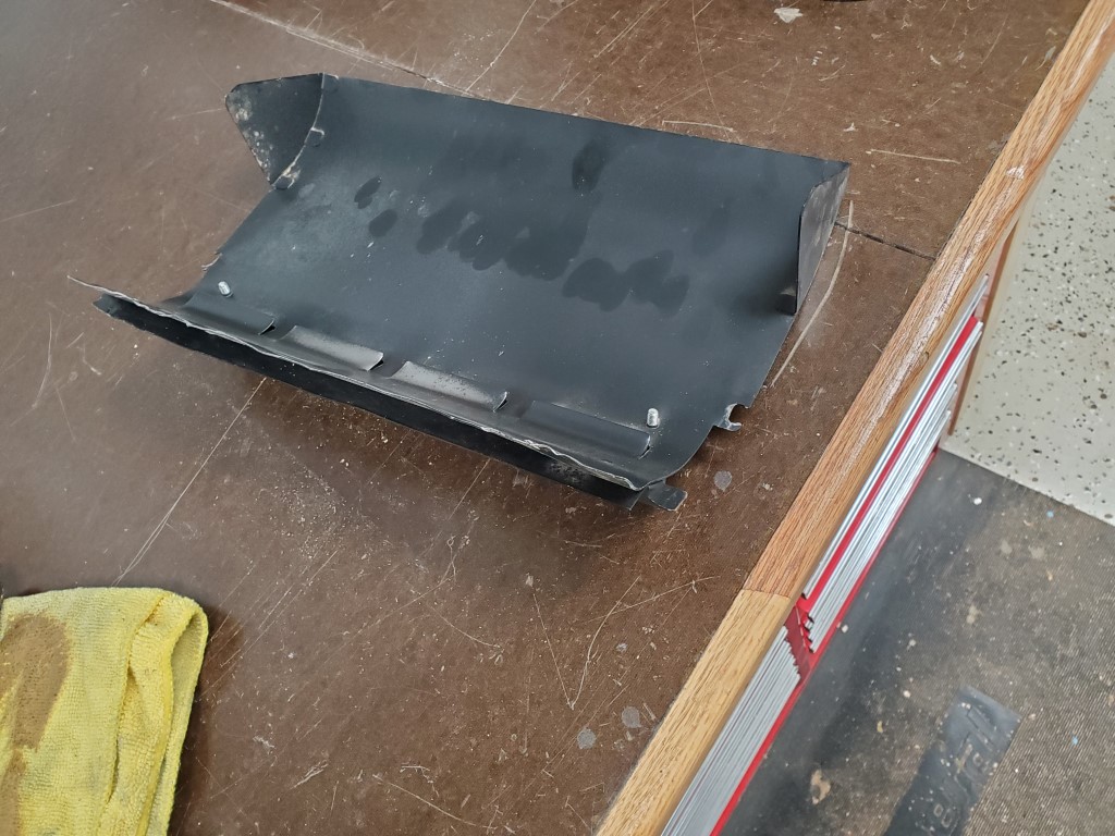
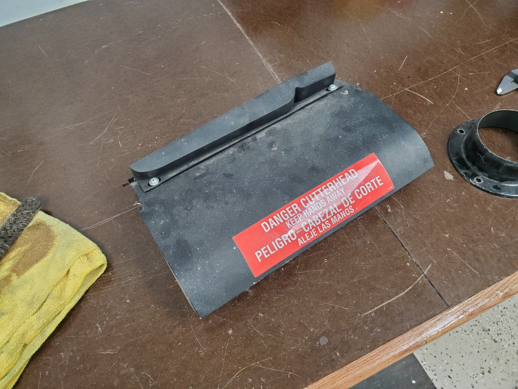
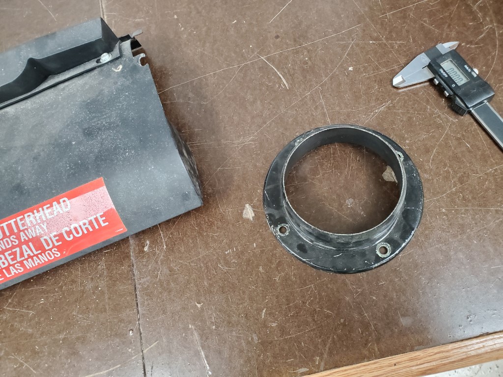
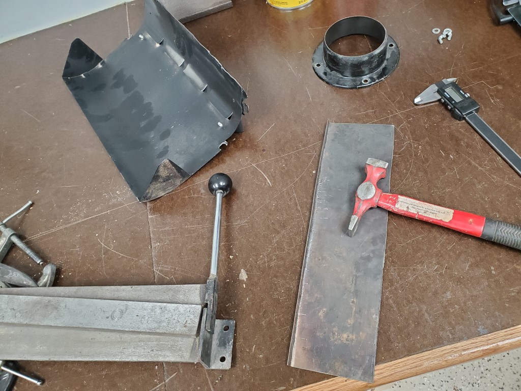
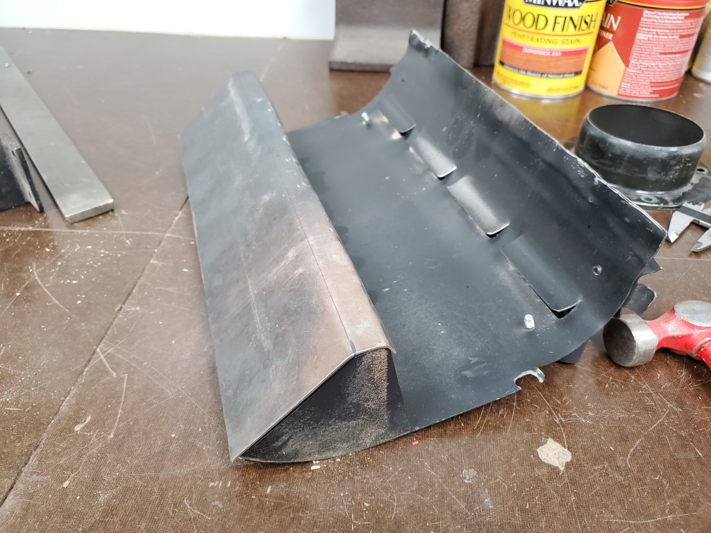
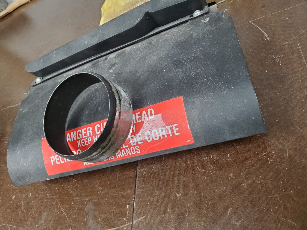
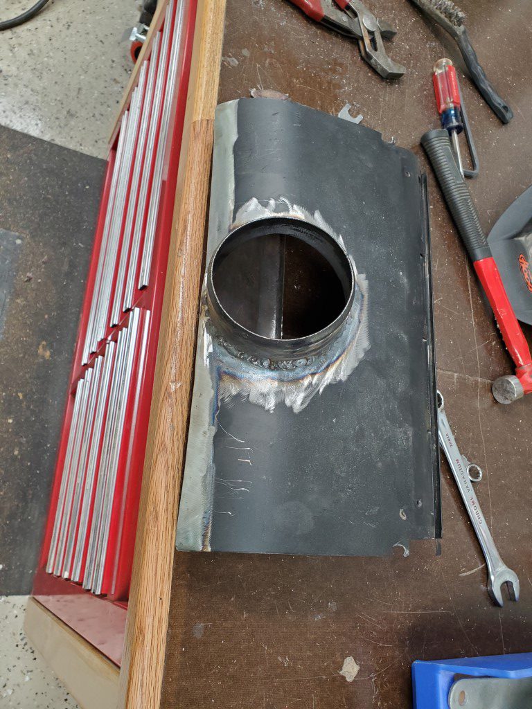
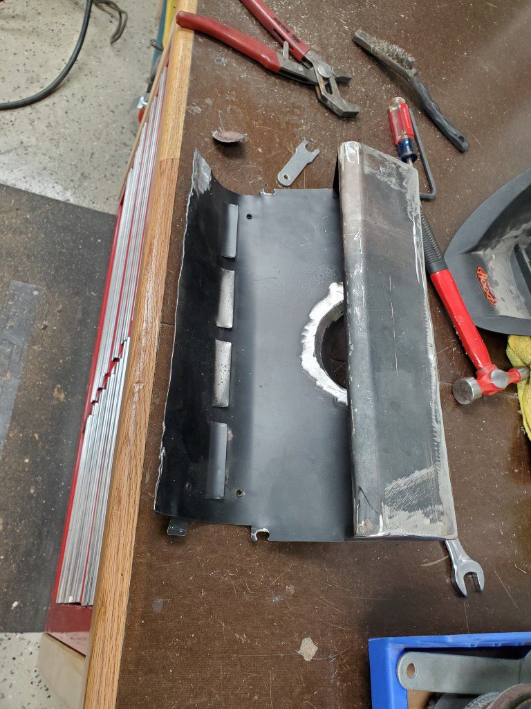
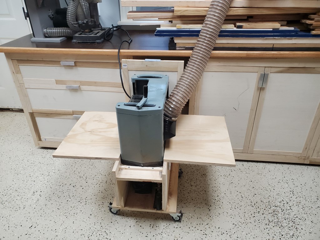
Planer Dust Collection
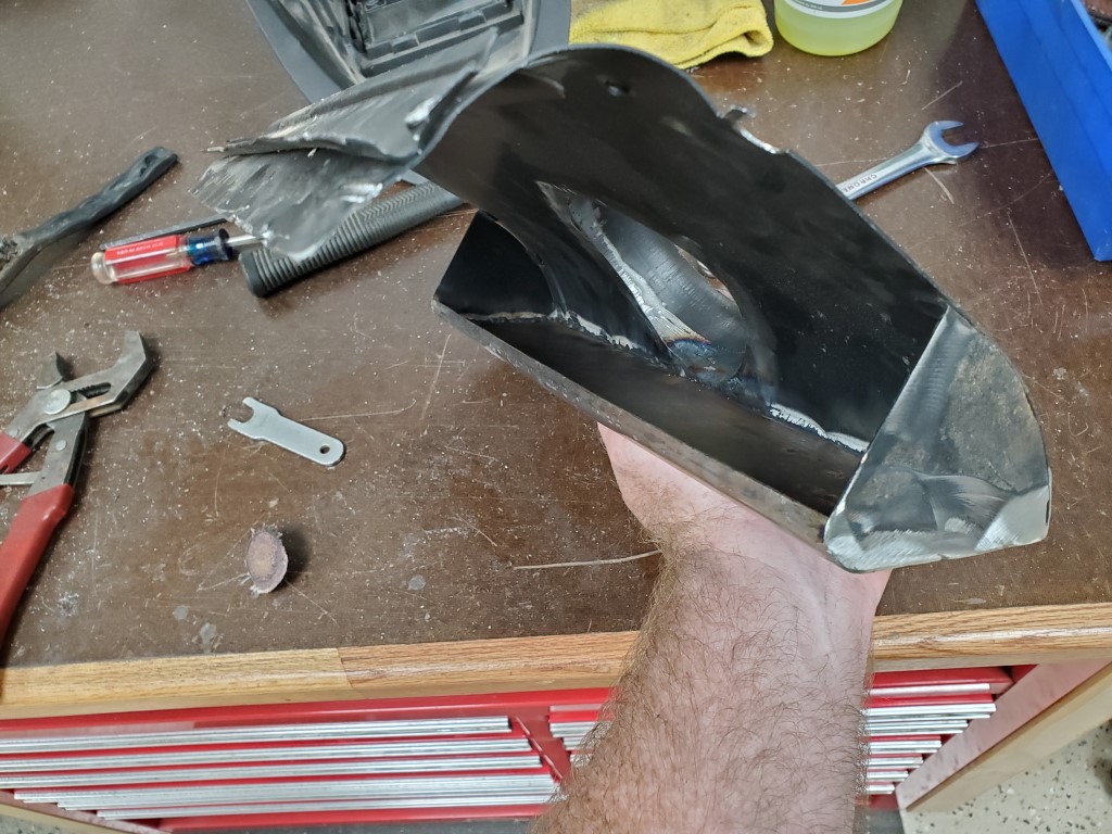
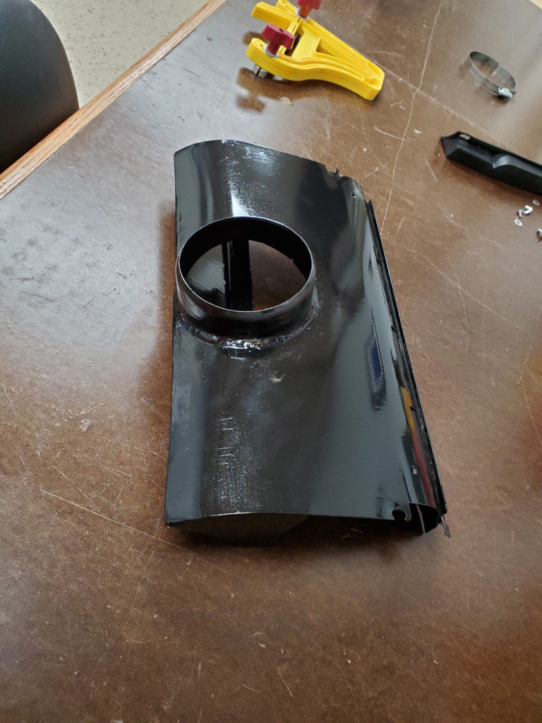
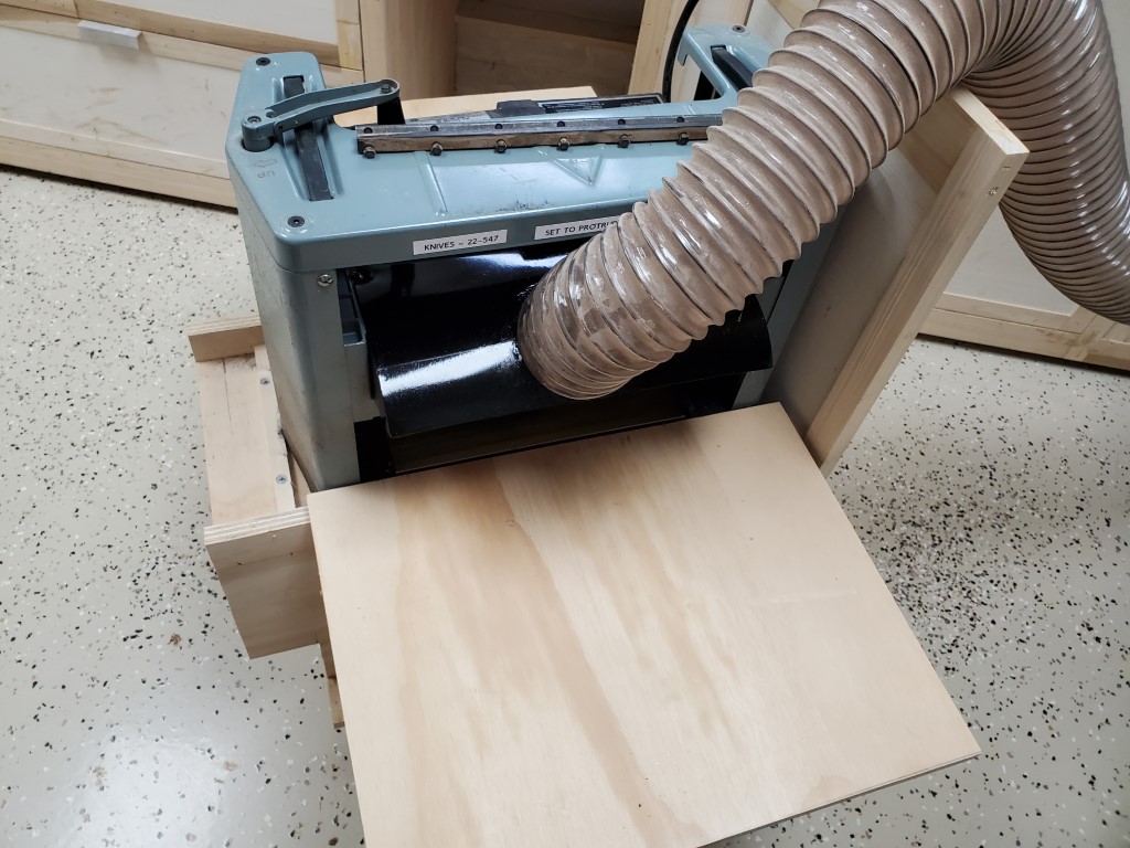
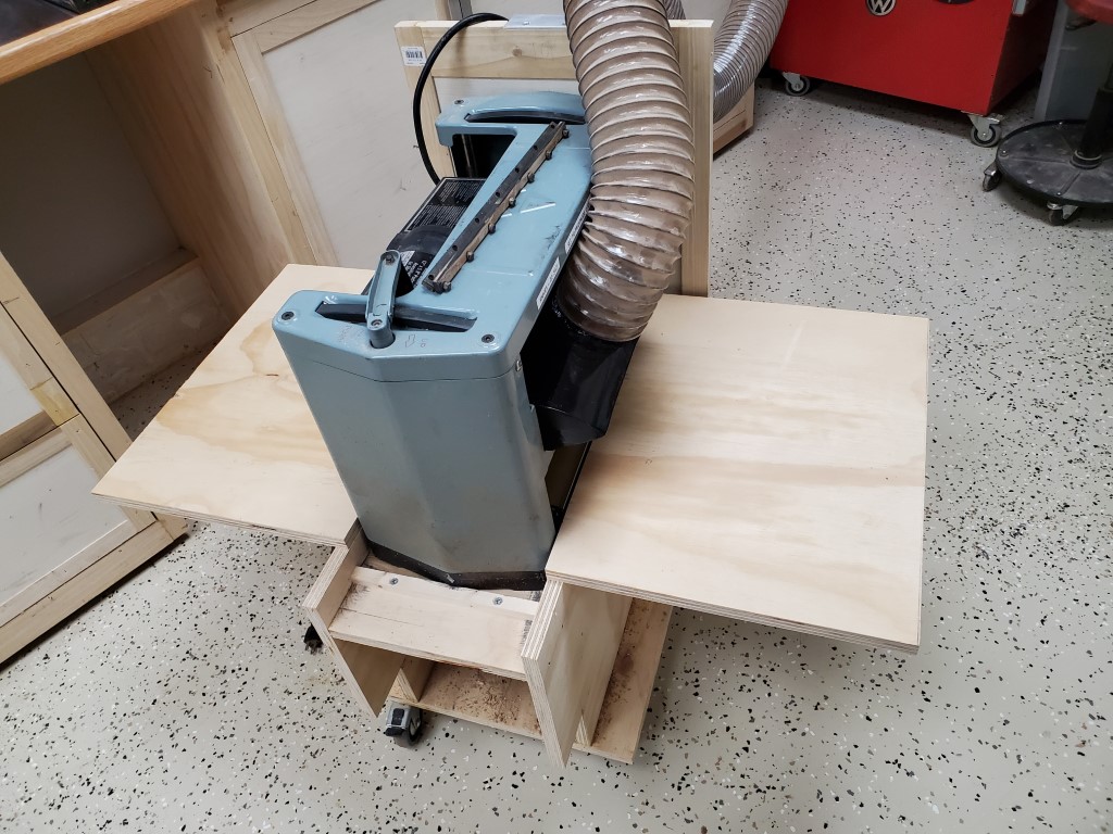
Quick fabrication project to add a dust collector connection to the planer. The planer generates by far the most chips/dust of any tool, so this will be a welcome addition.

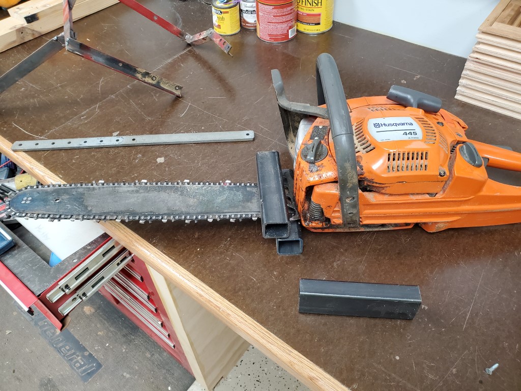
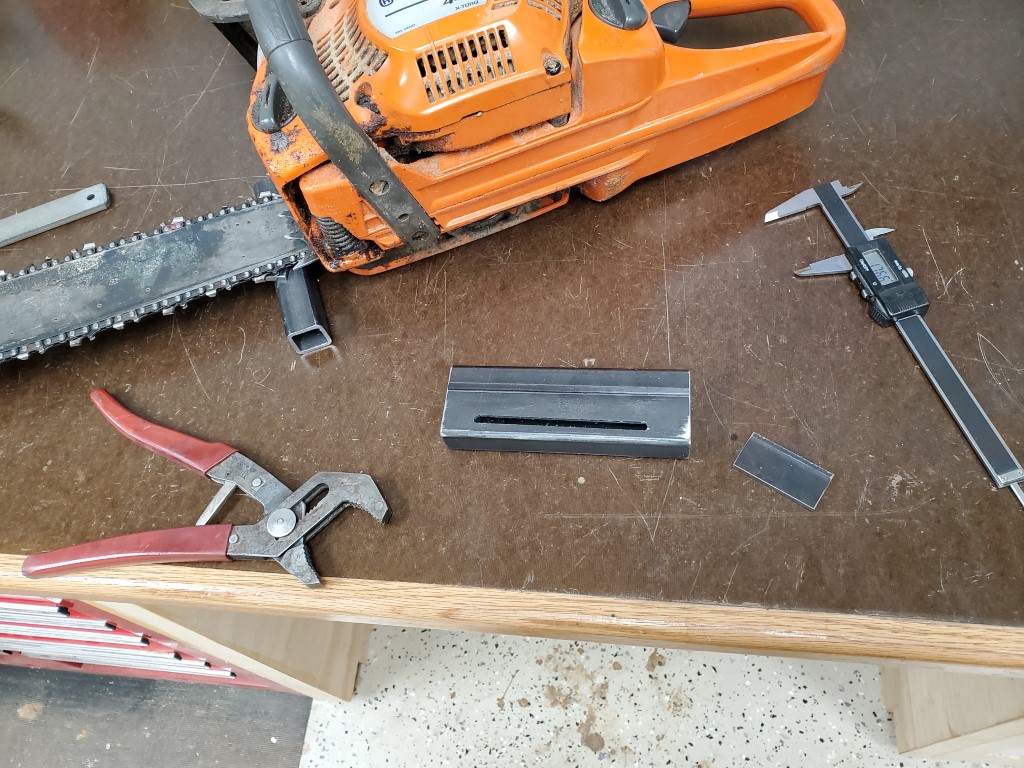
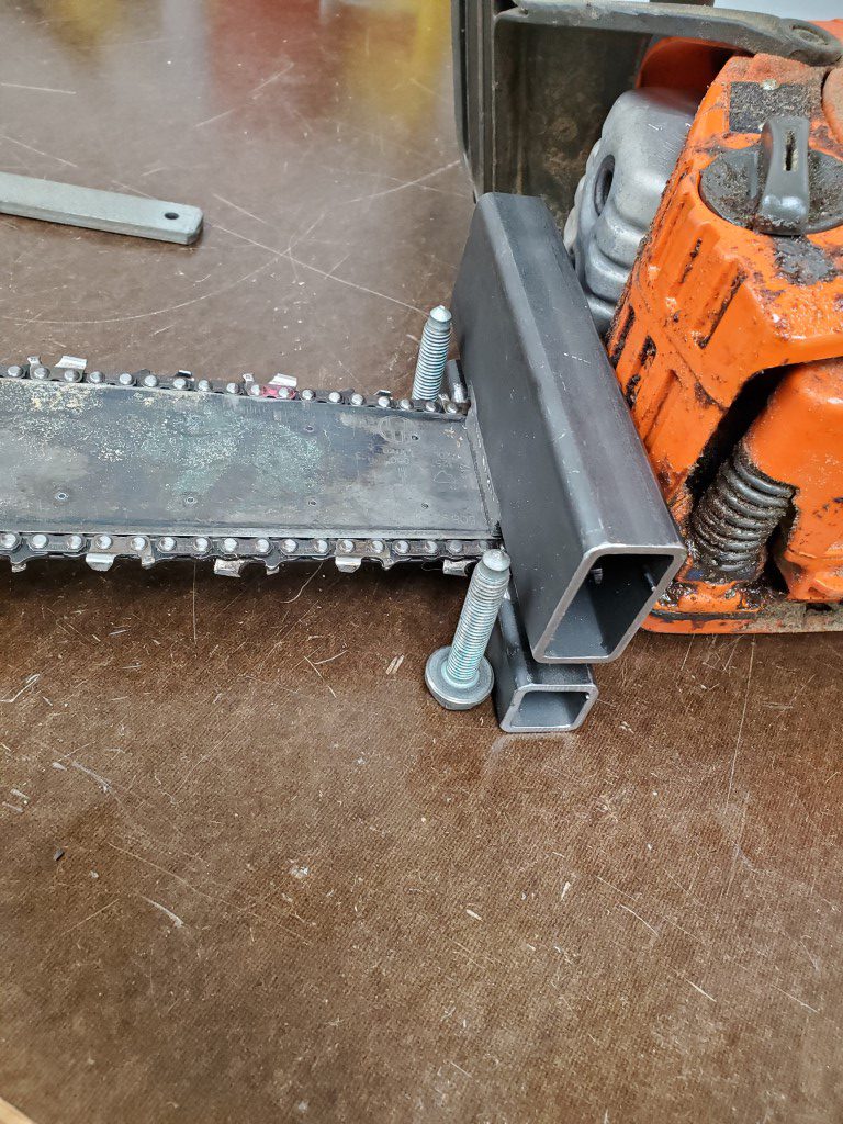
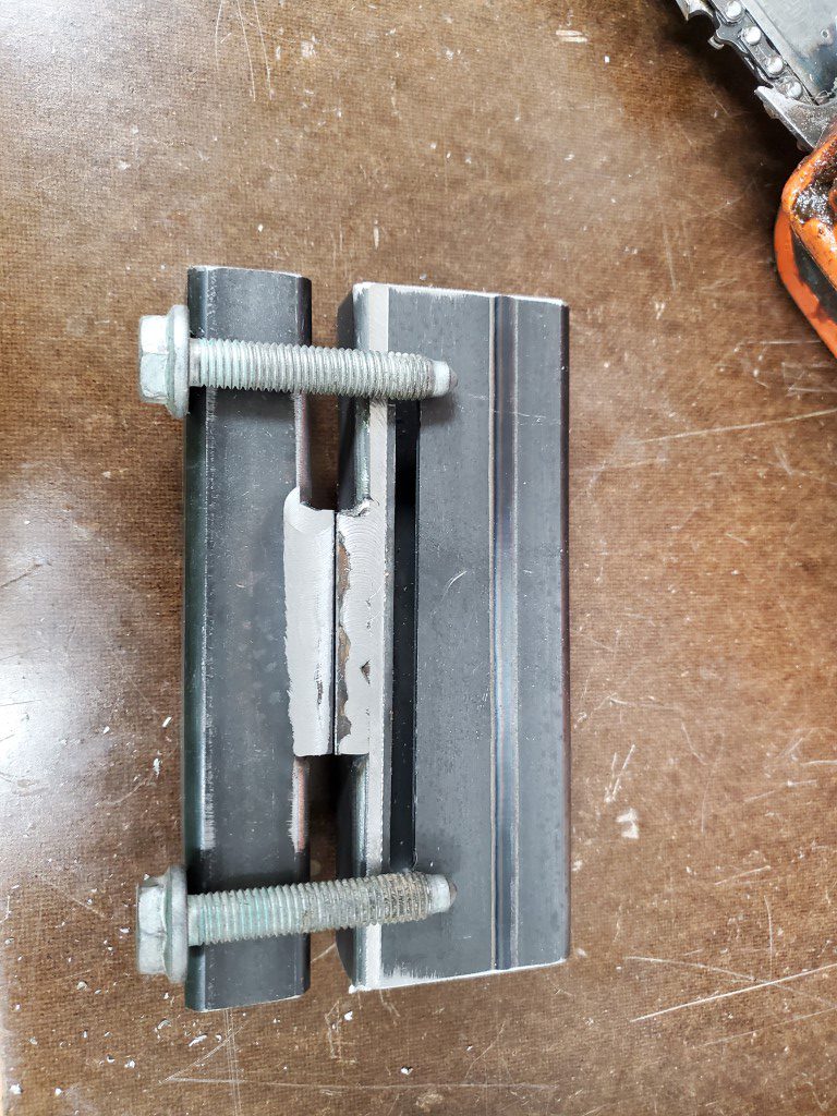
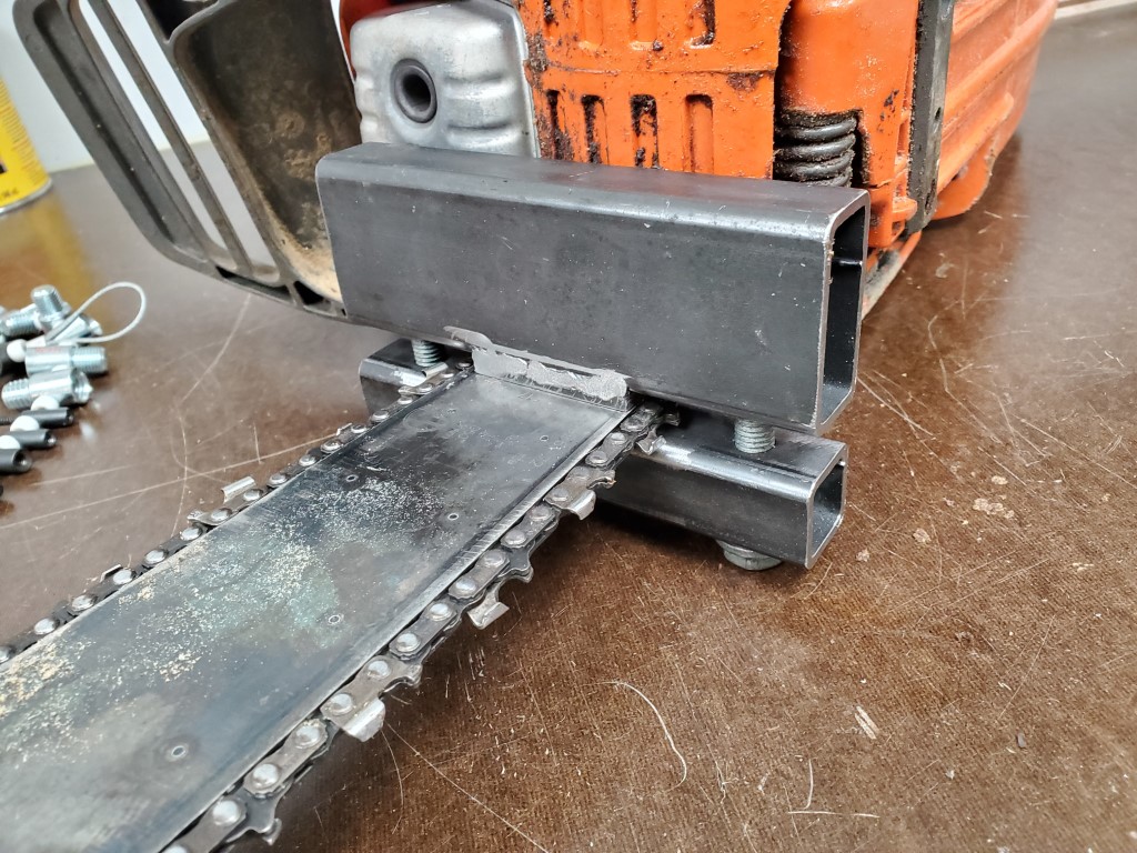
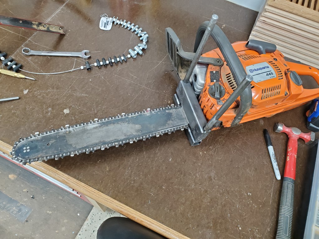
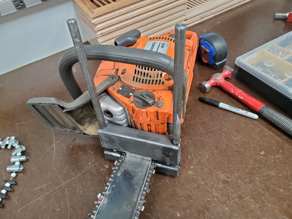
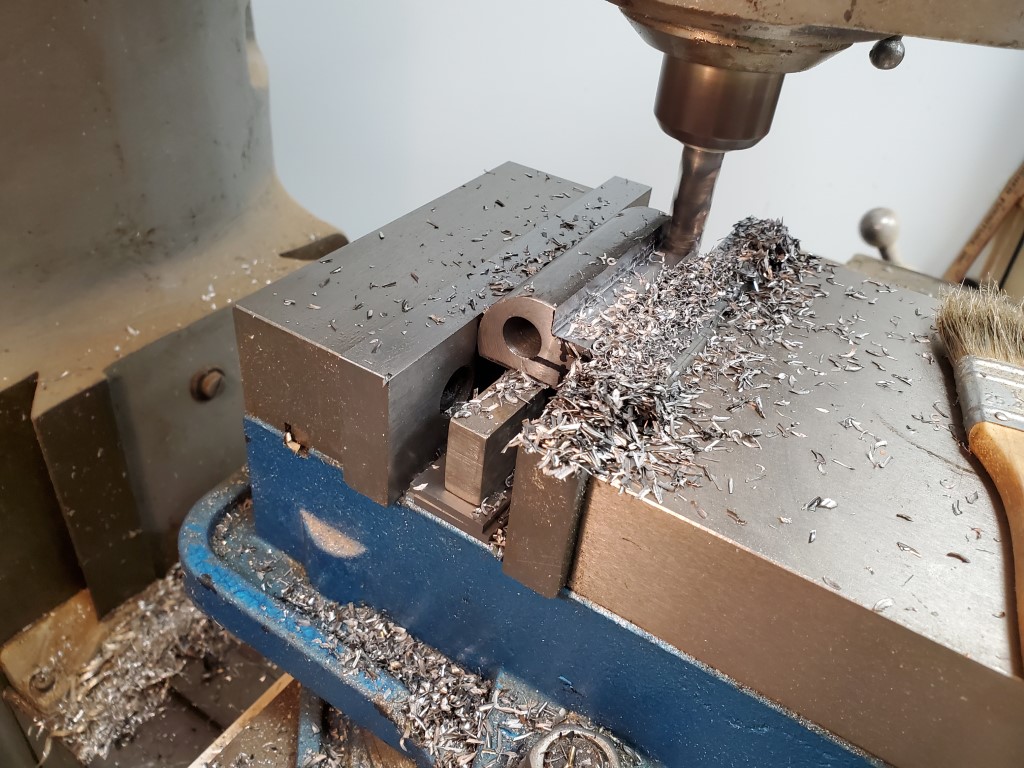
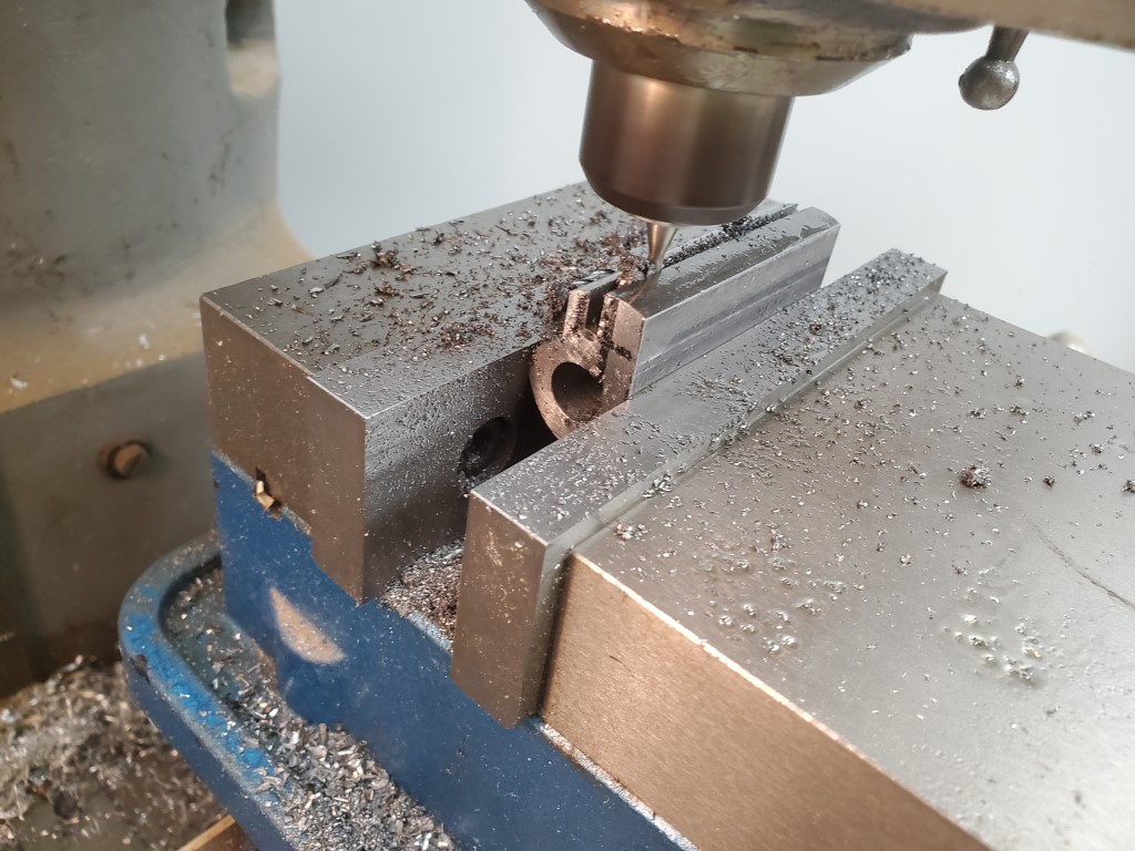
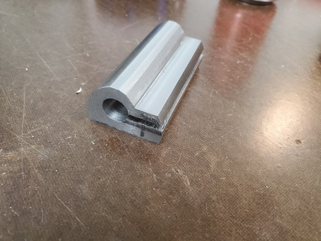
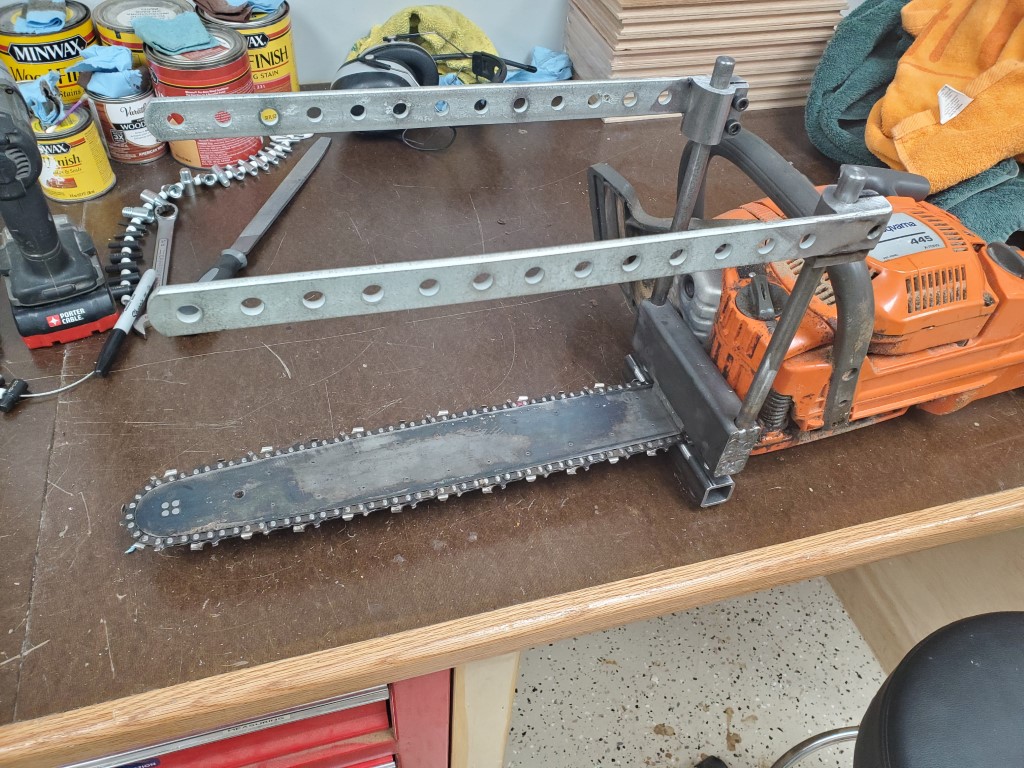
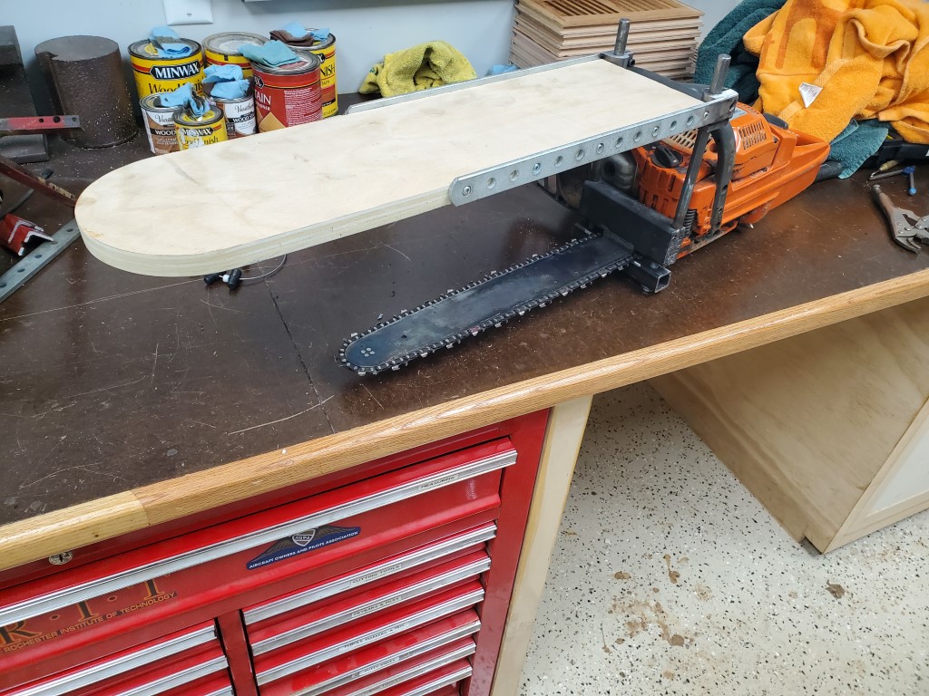
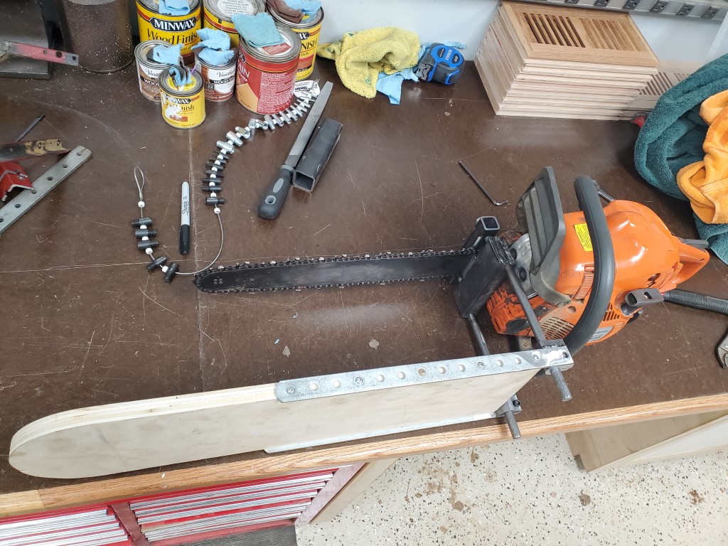
Chainsaw Sawmill v3.0
With the general success of the prototype chainsaw sawmill, I decided to make a more permanent/cleaner version. The idea is basically the same, but for easier installation/removal I decided to have this version clamp onto the bar rather then tie into the handle geometry. This version also allows for finer adjustment of thickness of cut via a sliding fence. (the previous version was only adjustable by adding/removing shims)

Trailer Light Upgrade
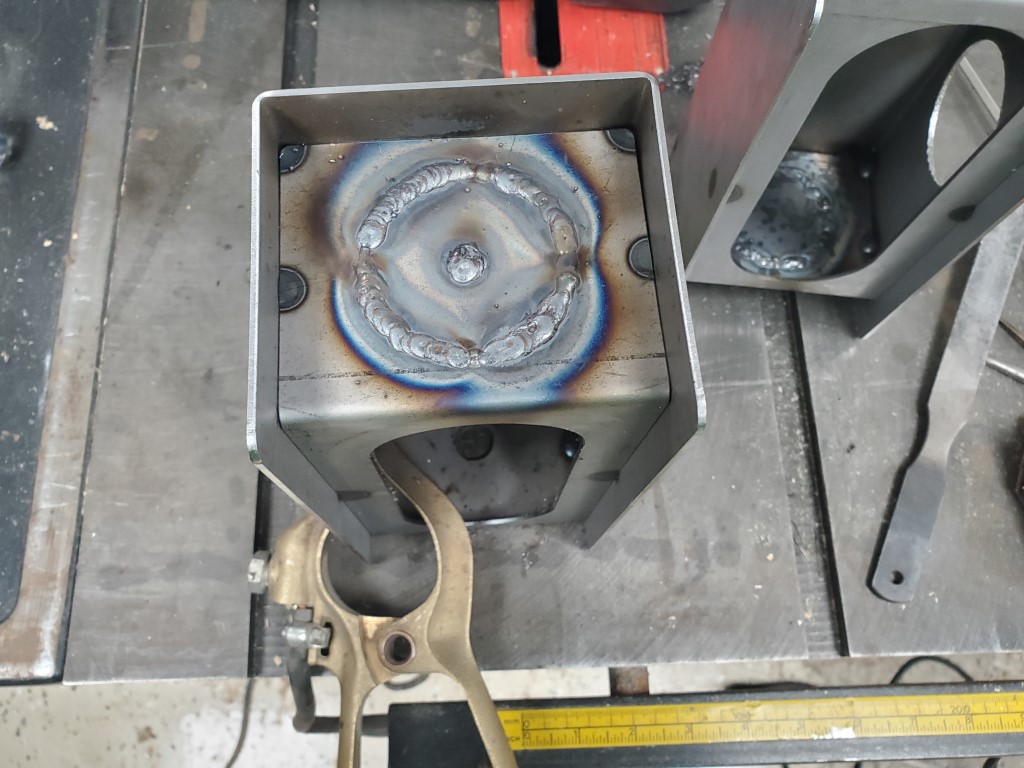
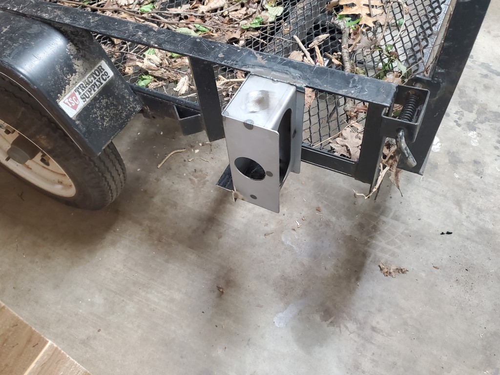
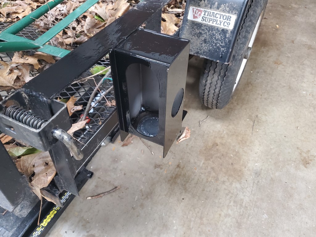
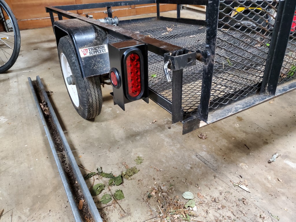
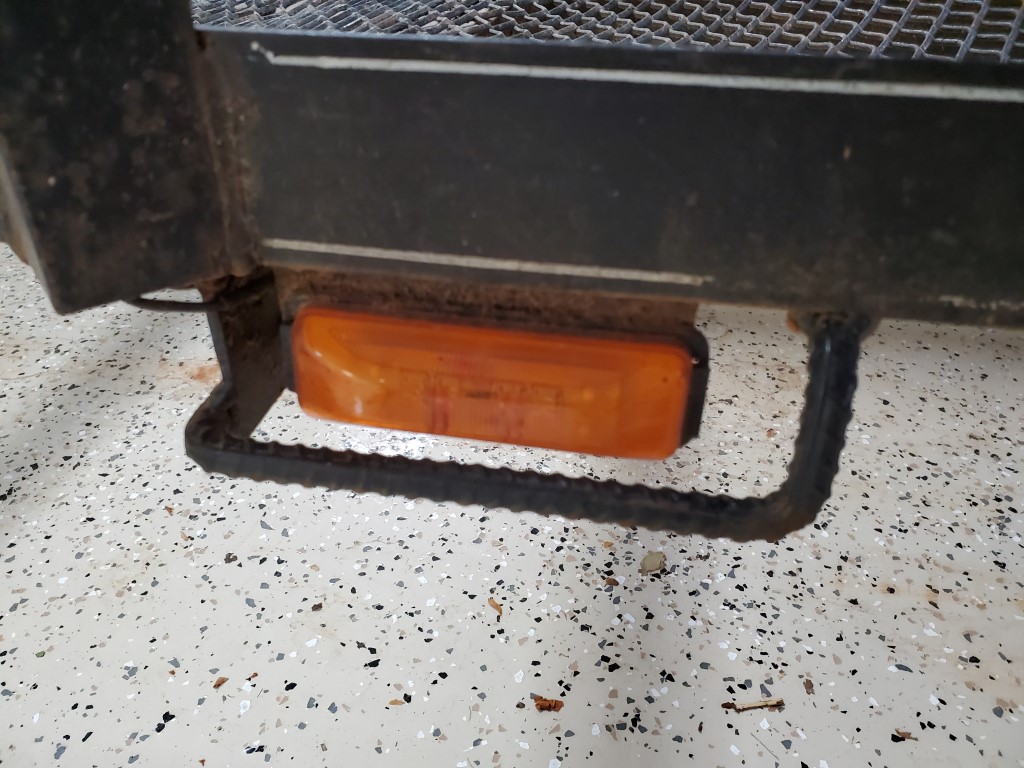
The utility trailer frequently gets used off-road around the yard and woods for moving downed trees/branches, compost, rock, tools, etc. As a result, the standard plastic lights have taken a beating and I’ve had to replace them at least once. Since one of the lights was broken again recently I decided to upgrade them to use a standard all-metal semi trailer style light enclosure. This style of light fits better vertically than horizontally on this trailer, so I modified the enclosure to move the circular side light from the end of the light to the side. I then welded the light enclosure onto the trailer; the size of the light worked out perfectly to connect it to the old light mount and also the top rail of the trailer on each side, making it very strong. At the same time I replaced the side running lights with a low profile LED version and added a guard/deflector made from a small section of scrap rebar.

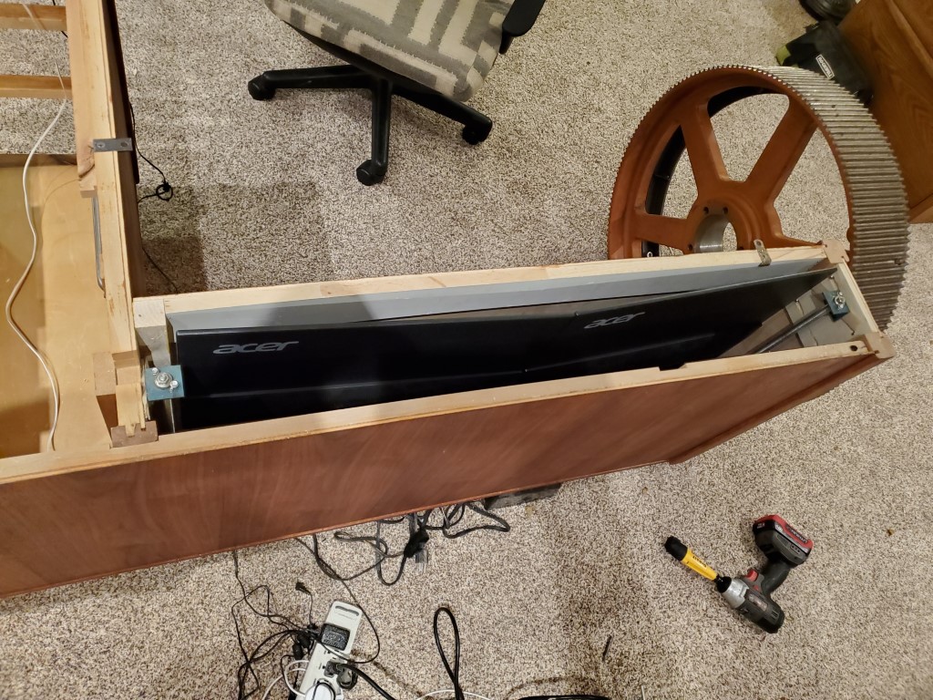
Custom Desk – Monitor Lift Mechanism
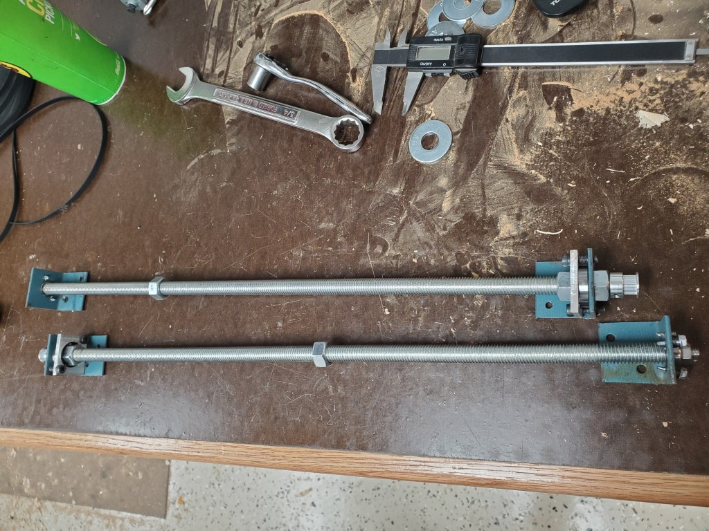
I got the idea for the monitor lift from an example online using all-thread as lead screws to drive a platform. Essentially I’m just replicating this idea but with a few tweaks that take advantage of having the lathe to make it better/stronger, easier to build, and to take advantage of spare parts I already had.
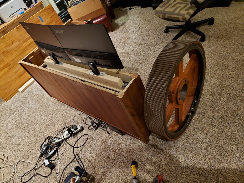
First I cut the all-thread rod to length and then I turned down one end of each to fit the inside diameter of some spare bearings. I left an extra bit on the end and turned it down to fit the inside diameter of a timing belt drive sprocket – this was later replaced with a chain sprocket due to slipping. I repeated the same on the top side of each rod (without the extra bit for the drive sprocket) and then I cut some metal brackets to hold the outer bearings. I then cut a small platform and attached two nuts to it that would connect it to the threaded rods.

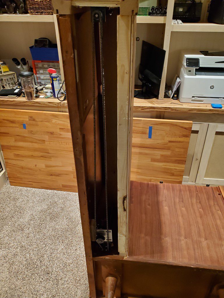
These parts were all assembled into the desk; a few small shims were needed to get the rods exactly parallel. I then connected the threaded rods together with a small #25 chain drive. To power the lift I tried a few different test motors and eventually settled on the guts from a small/cheap electric screwdriver – this provided enough torque while not requiring a huge power supply. It could be a bit faster and I need to add some sound damping, but it’s working very well for an initial attempt.


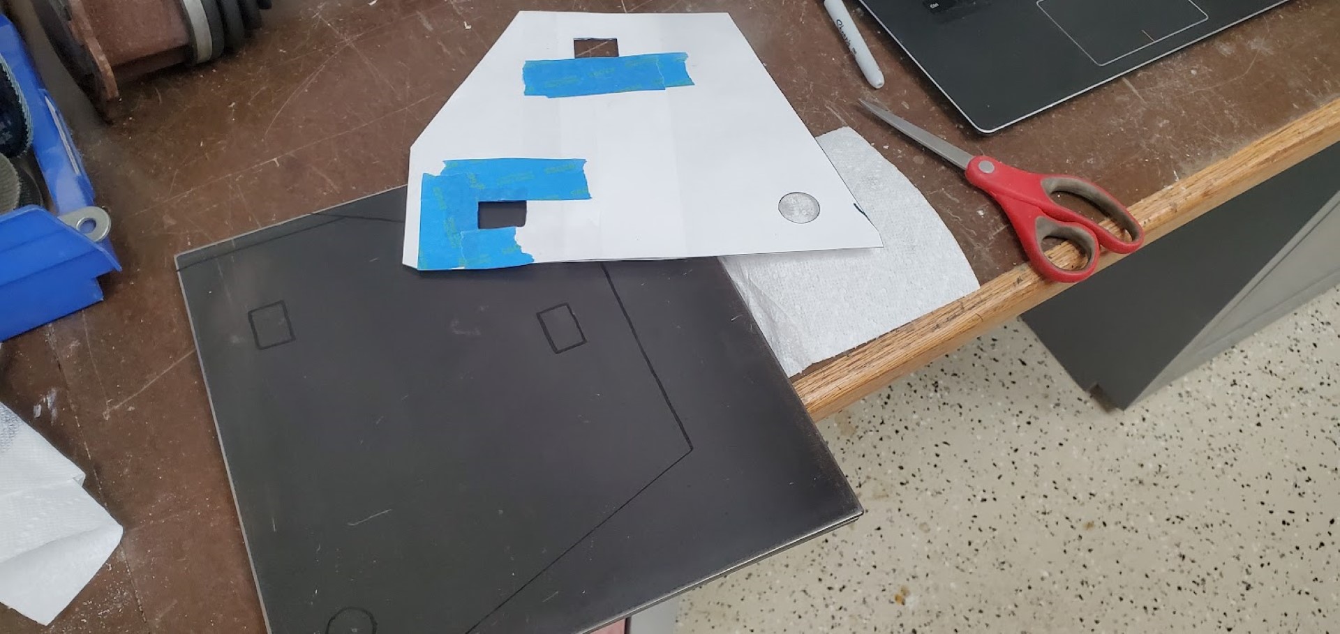
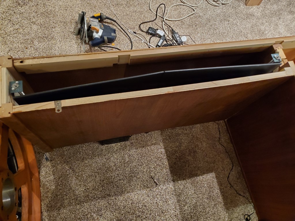
I also made some mounting plates to adapt the monitors to a fixed mounting since the regular bases were too wide. The monitors were then mounted to a 2×4 that acts as a spacer and also adds strength to the platform. Once the tabletop is in place the 2×4 and the rest of the mechanism will not be visible since the monitors will rise so that their bases are just flush with the top – I’ll likely add a trim piece to block this off. The monitors also drop low enough that the table top will clear with no problems.
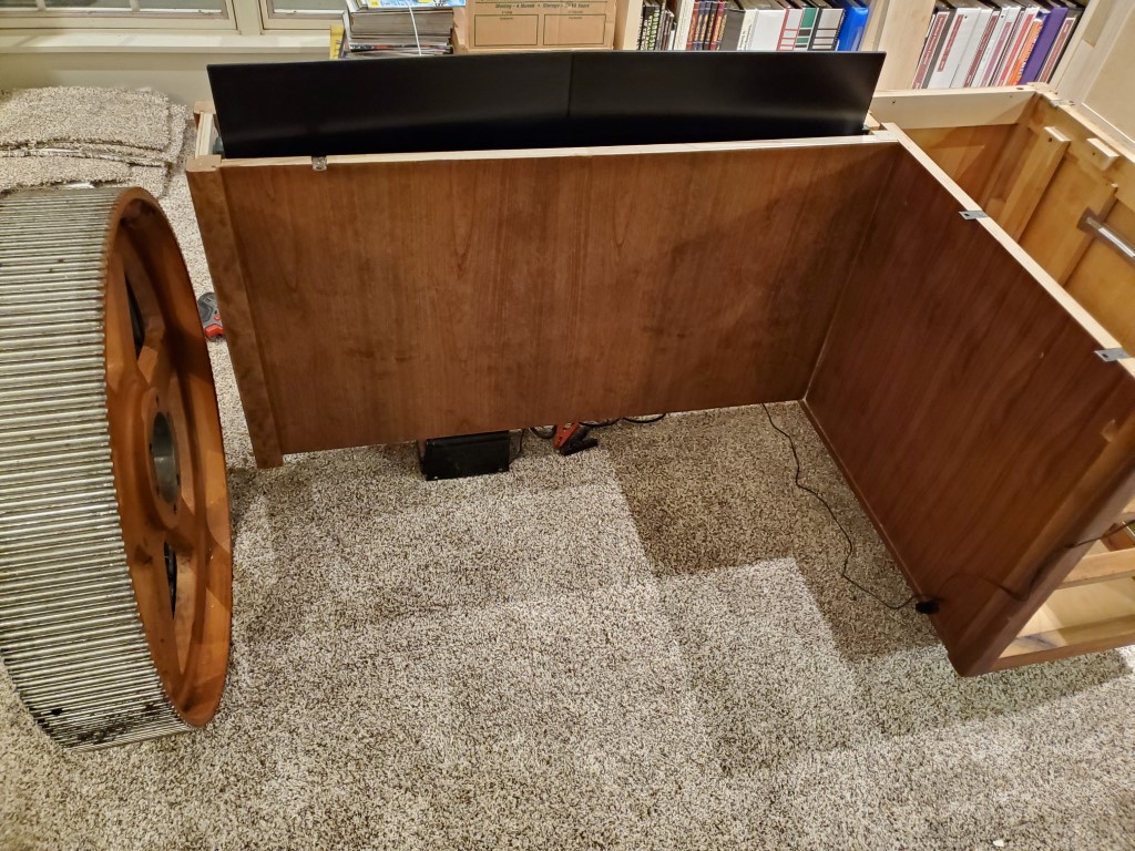
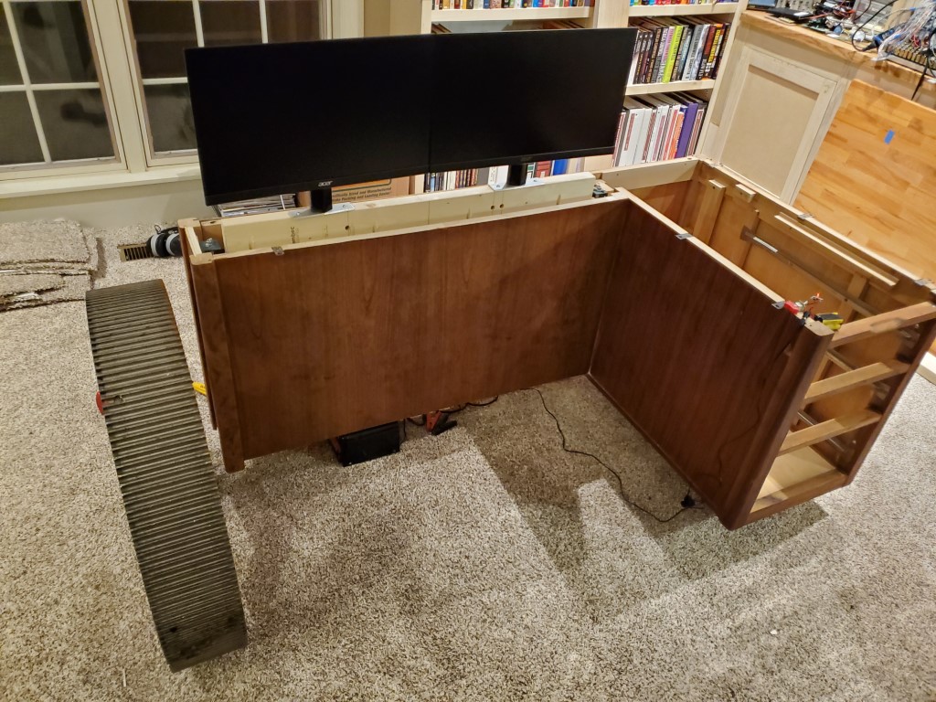
The last step was adding limit switches and rewiring – moving the toggle switch up runs the lift up until the positive switch is tripped, and moving the switch down runs the lift down until the lower limit switch is tripped.
Next up will be making the tabletop…
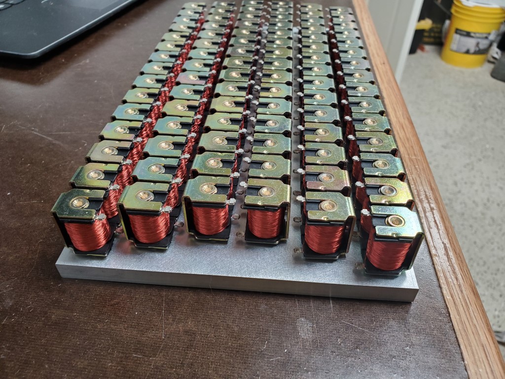
Piano Automation – Valve Manifold Complete
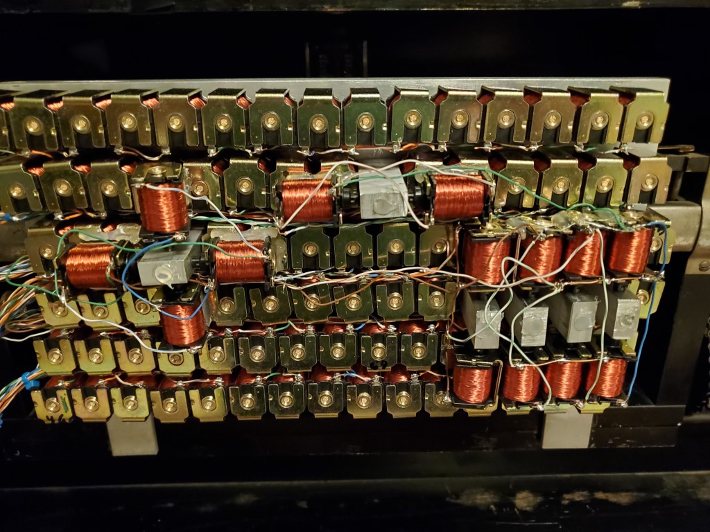
This weekend I had a chance to test the completed valve bank.
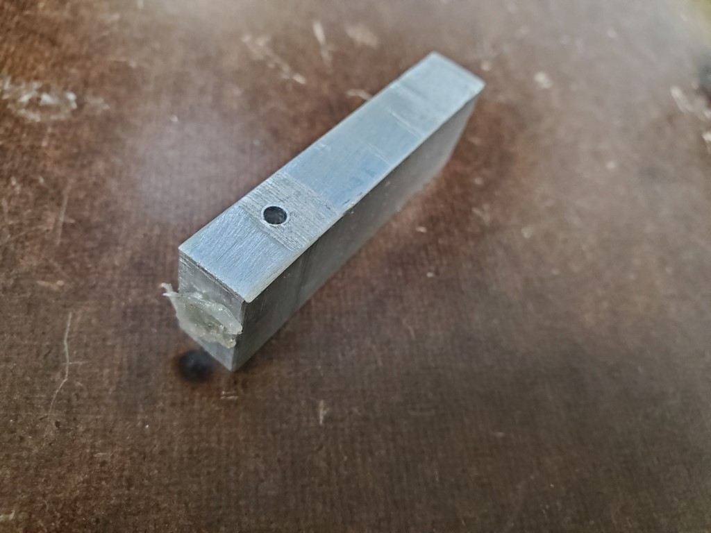
Testing revealed that some of the keys did not actuate with their corresponding valve open. On these keys when the valve (while turned ON/open) was removed from the manifold the key would strike immediately, pointing to lack of airflow through the valve as the cause. I can’t explain why this occurs on only some of the keys but the piano turns 100yrs old next year, so the inconsistency isn’t surprising. The piano could perhaps be adjusted to make these keys work the same as the rest, but I could more easily just provide more airflow via multiple valves per key – this is the approach I took. To connect multiple valves per key I created a few hollow standoffs that fit inside the valve holes in the manifold . The standoffs then have holes on their sides to allow connecting the extra valves on a 2nd layer above the rest. The end of the hole that was drilled to hollow the standoff was sealed with hot glue. Two valves solved the problem for most of the offending keys, but one extra special key required 4(!) valves in a ‘+’ configuration.

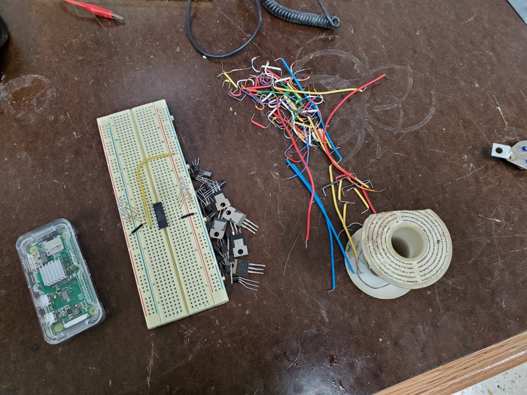
With the mechanical parts complete I’ve taken the first steps to construction of a raspberry-pi based controller that will use shift registers to power the solenoids. The raspberry pi and associated circuitry will be small enough to fit on the back of the valve manifold in the area where the paper roll would normally be. It has wireless connectivity and I plan to have it host a webpage where it can be controlled by phone/tablet. I’m bread boarding this first to prove the concept with one shift register, then once testing is complete I’ll create a circuit board to hold all 11.
Piano Automation Continued
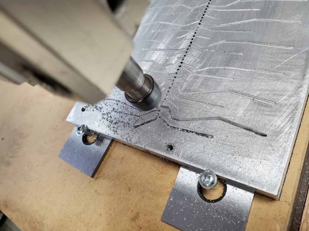
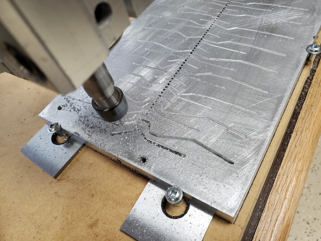
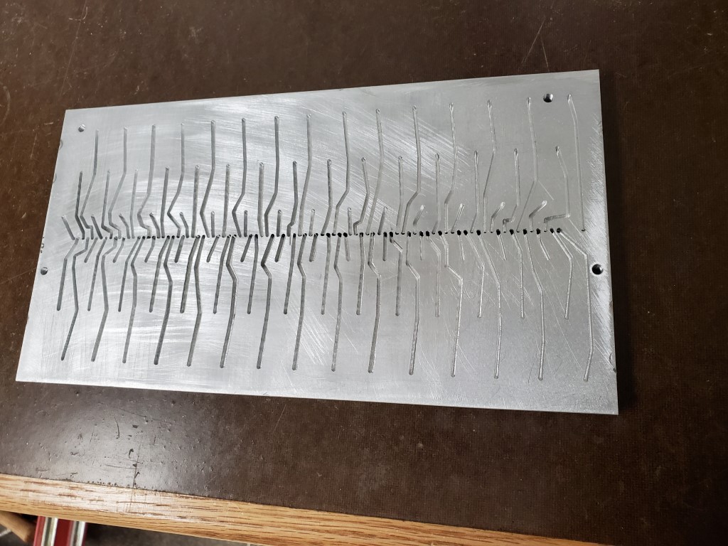
Over the past week I finished the lower valve manifold plate. The lower plate connects the row of holes on the piano tracker bar to the valves on the top plate. Obviously it would have been nice to just put the valves directly over each hole, but since the valves are much wider than the hole pitch I had to instead design the manifold with the valves arranged in multiple rows. Each tracker bar hole is connected to the valve above via passages that are routed into the bottom plate. The path of each passage was chosen carefully to avoid connecting to other valves/passages and to avoid running into the bolt holes that connect the manifold halves – each valve should connect to exactly one tracker bar hole. I let the CNC router do this work; it was relatively slow going with a 1.5mm end mill in aluminum but it turned out OK.
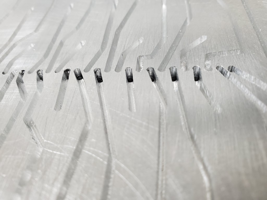
After the passages were milled I created a gasket using wide tape. The tape covers and seals the top of the passages and a hole punched at each valve location allows each valve to connect to its passage. The tape has enough compression that any imperfections in the plates will be sealed once the plates are bolted together. I also added a lip/shelf to the back of the manifold to hold it in vertical alignment against the tracker bar.
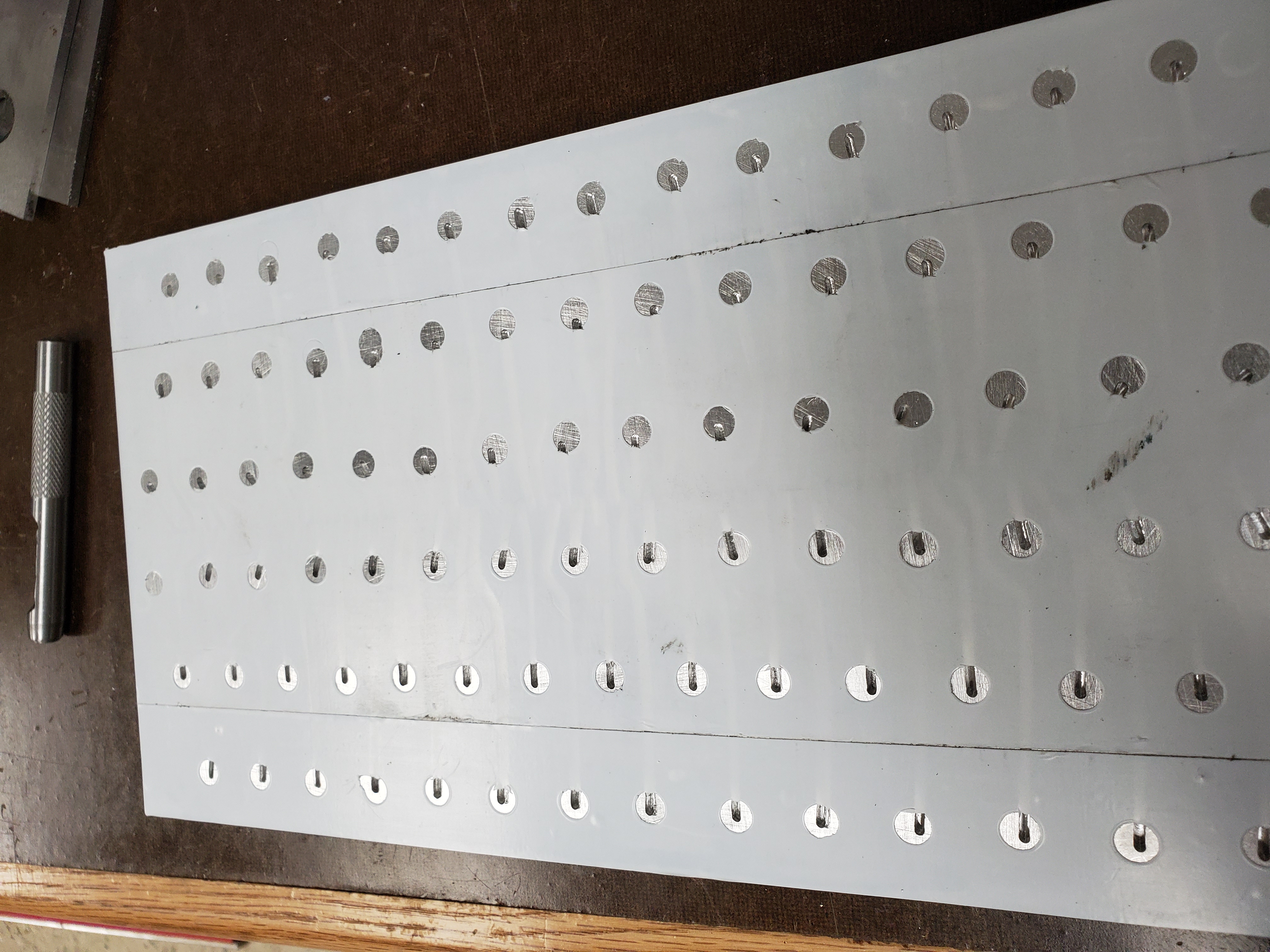
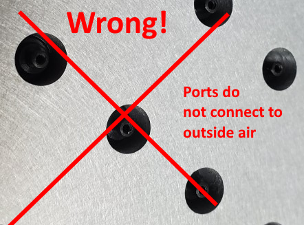
With the manifold ready, I connected it to the piano and tried firing the outputs. Results were not good, there was some vague correlation between outputs being on and notes being played but something was wrong. I had originally assumed the air passed all the way through the valves but closer examination revealed that they actually pass air from their stem to ports near the base of the stem. Since I had the entire stem/base of the valve mounted inside the manifold there was nowhere for air to flow when the valve opened. I re-made the top plate with smaller holes and re-installed the valves with only the stem in the manifold.

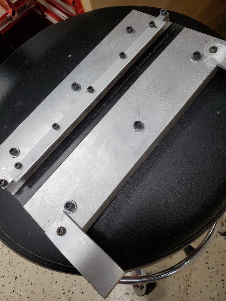
Remaking the top plate solved the valve problem but there were many dead notes due to air leaks at the tracker bar. I experimented with several materials to seal the tracker bar to the manifold and ultimately landed on thick rubber outdoor electrical tape as the best performing, though many leaks remained. I found that the tracker bar was not very flat and I was able to carefully bend it back. This helped considerably but leaks still remained. I found that the force needed to push the manifold against the tracker bar for a good seal had the effect of bowing the tracker bar away from the manifold in the middle, so I added a thin aluminum lip to the shelf on the back of the manifold. The lip is just thin enough to fit between the tracker bar and the wood cover behind it and it allows the manifold to hook over the top of the tracker bar and more positively hold the bar along the entire length of the manifold with enough preload on the tape to seal. This essentially solved the leak problem.
Currently there are ~12-15 keys that I’m tracking down problems with, this started from ~20 and was reduced by working through electrical/alignment problems. On the remaining dead keys I’ve ruled out problems on the piano side, problems with the lower plate, and any electrical problems; so next step may be replacing the valves themselves. It’s possible that those keys need more airflow, which would require milling their passages deeper and/or modifying the valves; hopefully it doesn’t come to that. Once they’re all firing though then the mechanical work on this is basically done and I’ll be able to shift focus to the control system side.
Piano Automation Begins
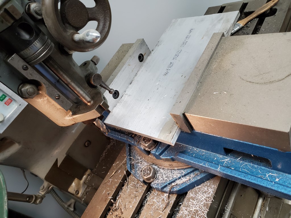
This weekend I designed and began fabrication of the parts needed for adapting the solenoid valves to the piano’s tracker bar. This adapter will consist of two 3/8″ aluminum plates. The top plate will have holes to accept the solenoid valves, and the bottom plate will have holes to interface with the piano’s tracker bar. Grooves will be machined into the bottom plate to create airs channel between the tracker bar holes and the solenoid valves above. The two plate will then be sealed together, covering the grooves; a similar construction technique as some carburetors. As long as the grooves are carefully routed, each valve should connect to exactly 1 tracker bar hole.
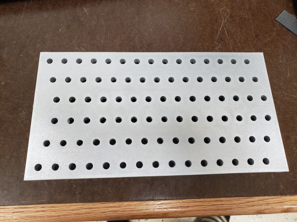
I cut the 3/8″x6″ plate on the band saw and then milled to final length. I used an edge finder to locate the plate edges, and then used the mill’s digital readout to position above each row/hole. For each row I took 2 passes, first spot drilling with a center drill and then drilling to size with a twist drill. 88 * 2 plates * 2 passes = 352 cycles of positioning the X axis and drilling a hole. Once all the holes were drilled I sanded sides to remove burrs from the holes and scratches from the rough plate.
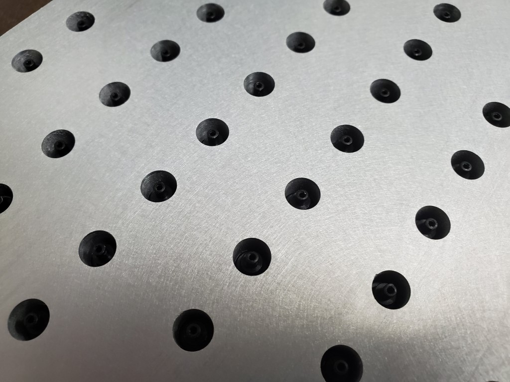
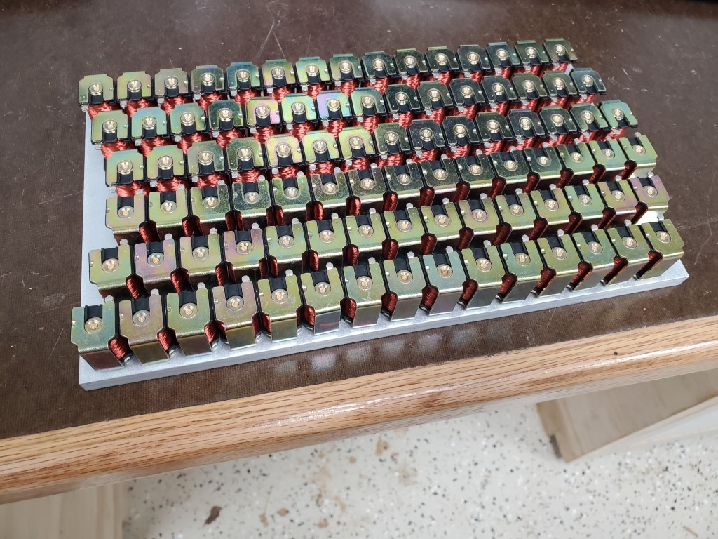
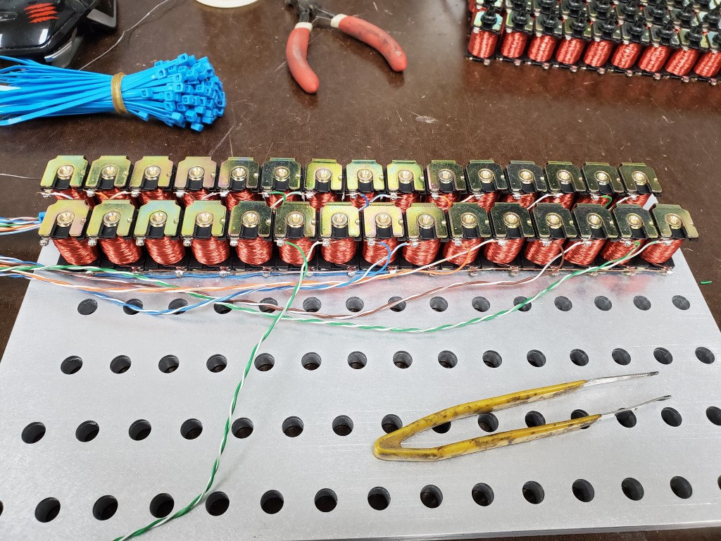
Next I installed and wired the solenoid valves in the top plate. The solenoid valves are an exact fit to the hole, but I added a bit of CA glue to ensure they stay in place. Wiring consists of scrap Ethernet cord that’s been stripped back; Every ~7 solenoids each share a common wire to reduce wiring, but it’s still ~100wires.
I’m happy with the results so far; this is by far the most precise thing I’ve made on the mill and everything is lining up perfectly. The next step will be to 3D model the grooves and convert these to paths to run on the CNC router. I’ve done some aluminum milling with it previously so it should work out OK, especially since it’s just cutting the shallow grooves – I wouldn’t have trusted the router to drill the holes as well as the mill did.