Saw Milling v2.0
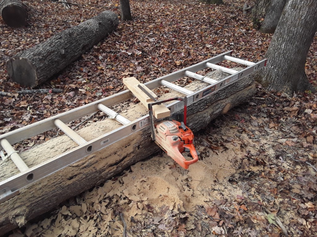
A while back, in anticipation of more log milling, I made a jig for holding the chainsaw level along the length of the cut. This is basically a homemade version of an ‘Alaskan Sawmill’, with a few changes. Since I processed last winter’s log recently it made room for another in the drying area, so I finally had a chance to test out the jig this weekend. For the first cut a ladder is secured to the top of the log to establish a reference surface.
I opted on not tie the reference block into the end of the bar, since I have a limited bar length. Because of this, I also couldn’t make the reference block adjustable without introducing too much flex. Instead, I set it at the maximum board width I may need, and for all thinner boards I’ll add more wood to the block or log to shim it. This also gives me the ability to cut from both sides for a log that’s up to ~2x the bar length.
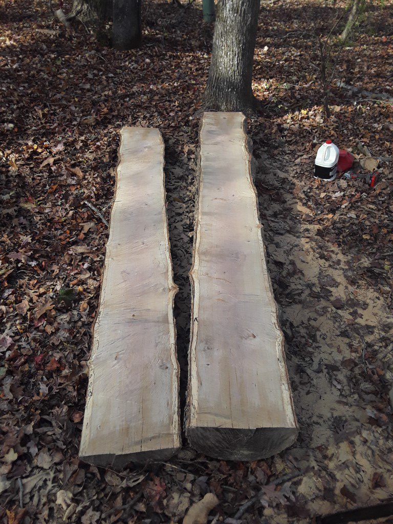
Altogether this test seemed to work great, the cut was extremely flat compared to the previous log that was cut free-hand. It was fairly slow-going though since I was using a standard chain; I have a ripping chain on order that should cut faster with the grain, I’ll install it before finishing this log.


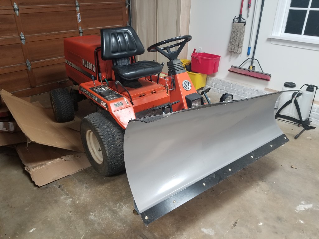
Kubota F2000 Snow Plow
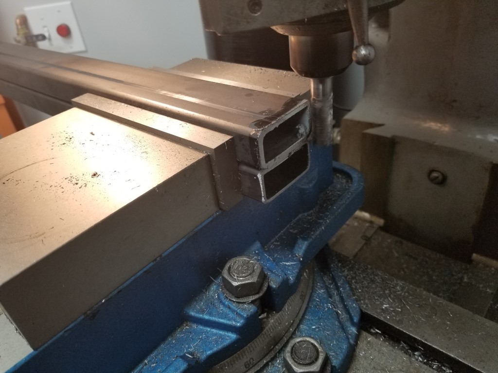
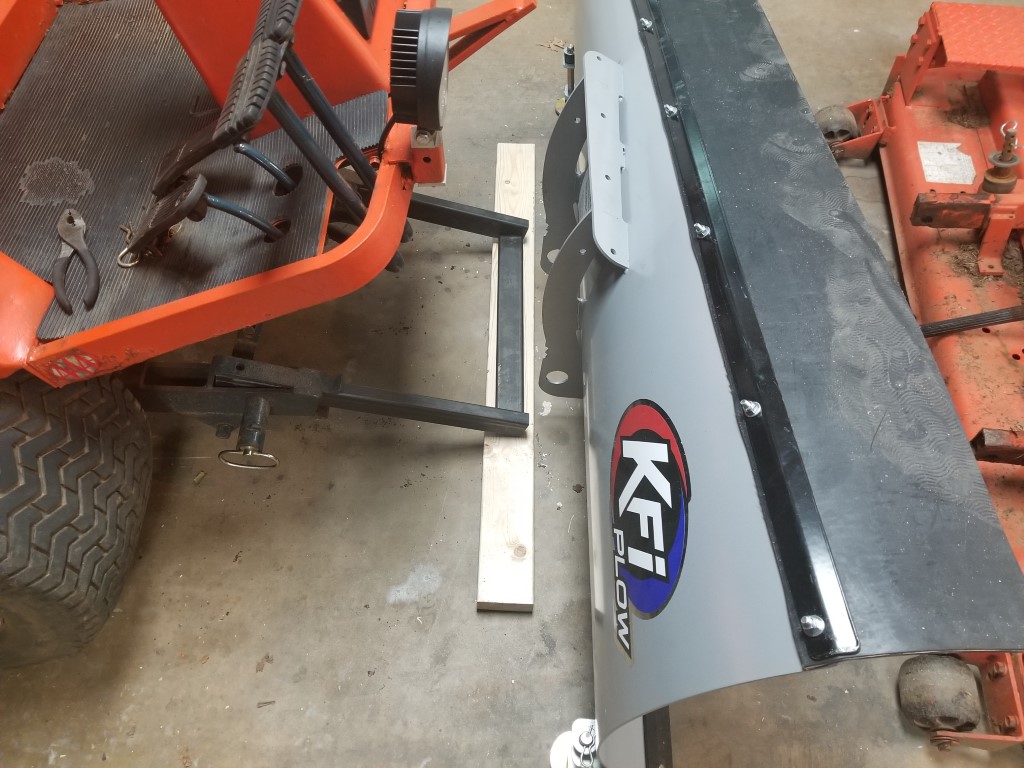
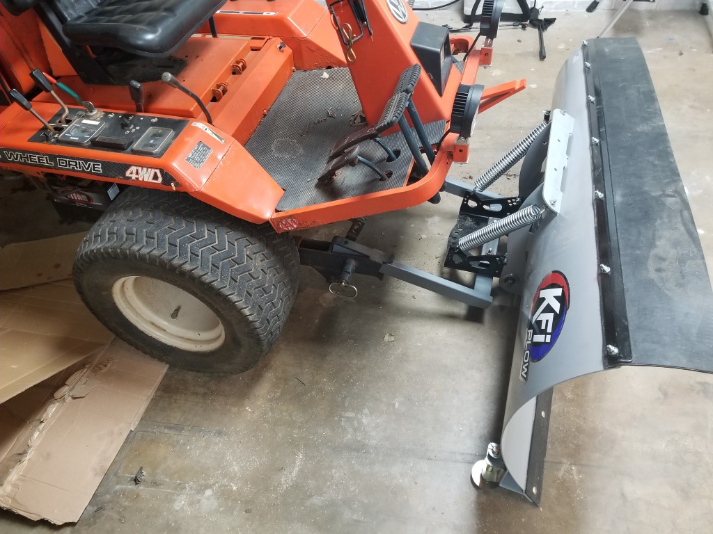
We don’t get much snow here, but when we do it takes a lot of shoveling to get out to the road. If conditions are just right we can be stuck for several days waiting for it all to melt. As a result I’ve had a mower/atv sized plow on my watch list since last winter. Recently a new open-box plow popped up that, after factoring in their free shipping, I got for basically scrap value or less. I think the reason for the low price was that it had originally been part of a kit, but all the mounting parts were missing. For my purposes that’s OK though – no one makes a kit specific to the F2000 anyways, so I was always going to need to fabricate the mounting parts myself.
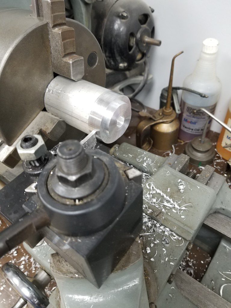
Making the mounting bar just consisted of cutting some 1″x2″ tube to length, squaring off the cuts on the mill, drilling holes for the pins, and then welding everything together. From there the plow’s base just clamped between the mounting bar and another section of tube.I made the clamping bolts fit just inside the plow base’s big hole so the plow can be rotated by loosening the bolts. Since the push bar connects to the standard implement mounting points, the plow can be raised/lowered the same way as the mower deck. I also needed to make some stepped bushings on the lathe to fit the plow base to the plow.
Kubota doesn’t list a tow/plow rating for the F2000, but it’s 4WD with a 3 cylinder diesel and built exactly the same as a ‘normal’ compact tractor, the only difference is that its seating position is spun around 180deg. For occasional plow usage I don’t foresee any issues. I may need to tie into the plow base’s rear holes for stability and to prevent unwanted rotation, but I’ll try it out first to see if this is necessary.
As part of the plow installation project I also went through the mower’s electrics and replaced a lot of corroded connectors with solder/heatshrink splices. It turns out the glow plugs hadn’t been working all along. With the glow plugs now working it starts a lot faster and in winter this will likely be a necessity to start at all.


Hacking the Player Piano – Part 1
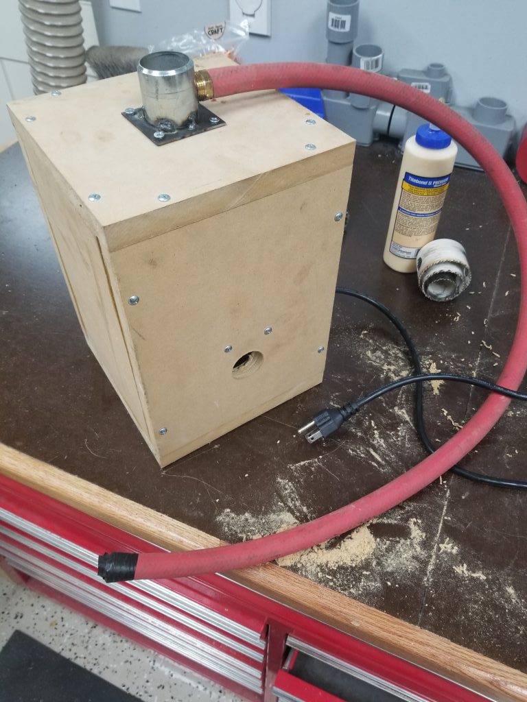
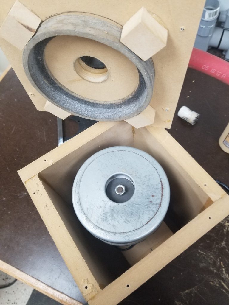
It was only a matter of time before this happened – the player piano (original post) is a real workout to play manually. Since it works on vacuum, I had set aside the motor from an old vacuum cleaner for potential use in powering the piano. Tonight I built a small box to contain the vacuum motor and connect it to the piano. The box is made from MDF, partly because I had scrap that needed to be used, and partly because it’s very heavy & sound absorbing. I made the big fitting by cutting/milling a square from scrap, I then bored a hole in it on the lathe and welded it to a scrap of pipe.
One very large hose goes to the manifold powering all the key bellows, and another smaller hose powers the vacuum motor for the tracker/scroll mechanism. I didn’t notice the smaller connection at first, so I had to go back and tap a fitting into the connection for the large hose; there’s still enough room for both to connect though.
Overall it seems to work great, this effort was definitely a quick proof-of-concept though and I’ll need to go back and fix/test a few things:
#1 – Motor controller to slow down the vacuum motor. Currently it has way more vacuum than is actually needed and slowing down should reduce noise from the motor.
#2 – Ensure cooling is OK. Especially after slowing the motor down I need to test that air flow is good enough to keep the motor consistently cool.
#3 – Mount in piano base and complete further noise insulation.
#4 – Tee hoses (and potentially add check valves) so that manual operation still works.
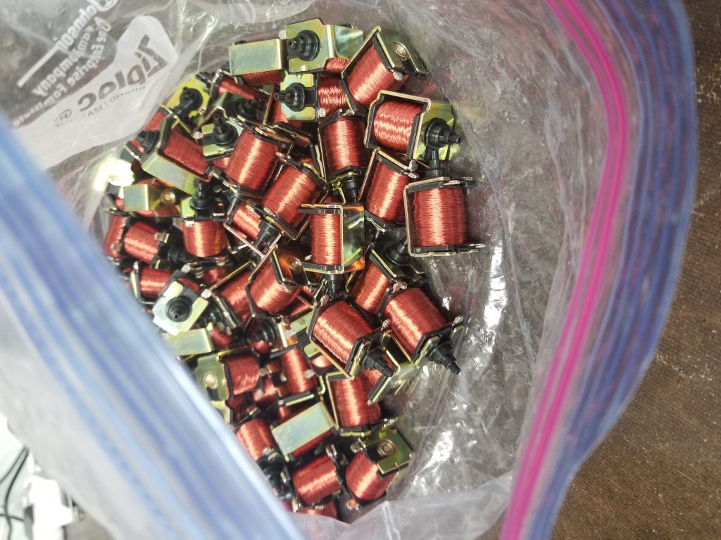
Beyond that I do have plans to eventually (could be tomorrow, could be in 5yrs) automate the player mechanism using some small pneumatic solenoids I found on ebay. These would tee off of each line from the tracker bar and when they open it would simulate a hole in the paper passing by. With this it would then be computer controlled and able to play anything. By default these are off/closed, so the paper mechanism would still work fine, in computer-controlled mode I’d just need to block off the tracker bar holes with some tape.

Dust Collection
This weekend I installed the shop dust collection system. The system consists of several parts:
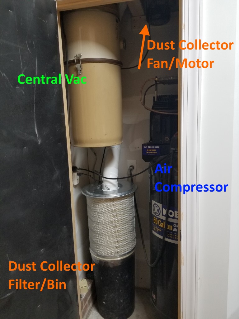
Fan/Motor: I repurposed a portable dust collector fan I’ve had for a while that’s been underutilized (collecting dust, but not as intended). Space is limited in the mechanical room so since the fan won’t need easy access I mounted it high up above the air compressor near where the dust collector pipe enters the mechanical room.
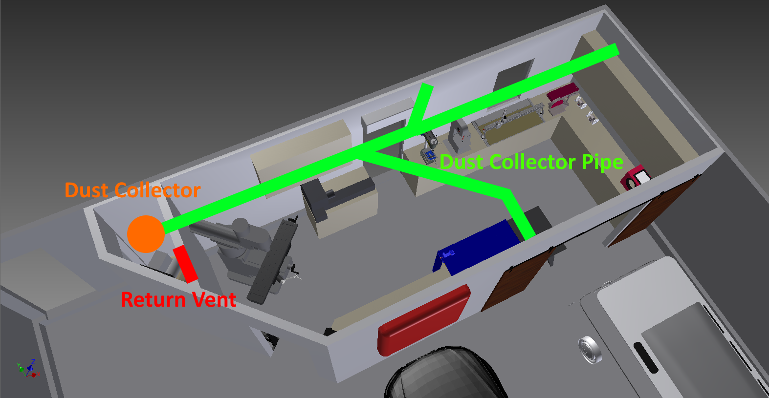
Pipes: 4″ PVC DWV pipes; there are a few branches leading to the different tools. I tried to keep the overall length as short as possible and the bend radius’s large.
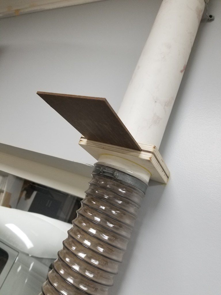
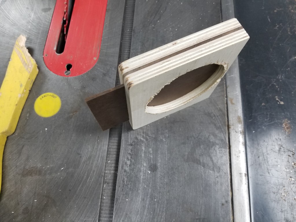
Blast Gates: The blast gates control the air flow though the system by blocking off unused branches. I made these with 1/2″ plywood and 1/4″ hardboard. Circle cutouts were made on the lathe to match the pipe outside diameter exactly.

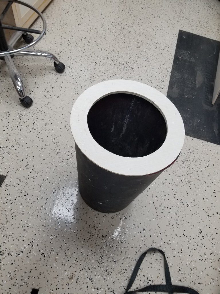
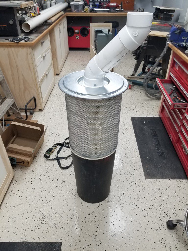
Filter and Collection Bin: The portable dust collector came with a light canvas bag that restricted the air flow massively while still allowing fine particles to escape. To improve this I replaced the bag with a semi truck air filter mounted to a trash can. The theory is that air will exit the filter and larger dust/chips should fall into the trash can below. There are purpose-built dust collection filters available, but the costs are much higher for these and the semi truck filter has the same specs; different economies of scale. To mount the filter to the bin I made a plywood ring, for now they’re just taped together but I may add latches at some point. The design may need some tweaking; I’ll know more after it gets further use, but for now the airflow is excellent.
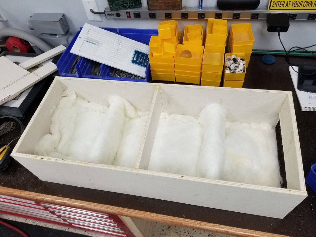
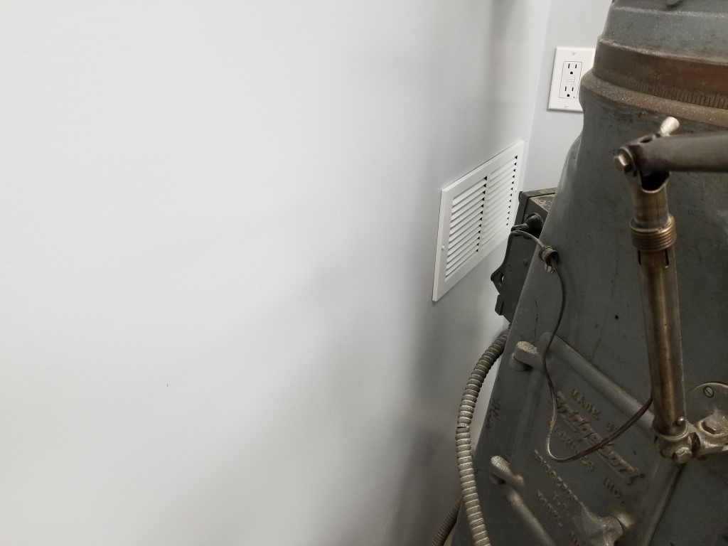
Return Vent: Having the collection bin in the mechanical room created a problem; the mechanical room is well sealed for noise reduction, so there was nowhere for the air exhausted from the filter to go. For heat/air to be retained in the shop, the exhaust air needed to return to the shop via a vent. Since I also wanted to keep the mechanical room noise level as low as possible this meant the vent needed to be sound proof. I built a sound proof vent by creating a 3ft long box and offsetting baffle plates inside of it. The sound has to reflect a dozen or more times off of the baffle plates; at each reflection it gets absorbed some by a fiberglass lining. The air, however, is able to snake around the baffles and find its way out. The inlet to this vent also points directly at the floor away from the sound sources. Somehow after adding this vent the mechanical room noise is actually noticeably quieter than when it was completely sealed. I think this may have had to do with the air pressure changes resonating in the previously sealed room, whereas now any fluctuations are equalized through the vent.
Control: For now control of the system is via a remote control outlet (repurposed from controlling the vacuum at the old shop), at some point I may integrate some low voltage switches with the blast gates so the motor will turn on as soon as any gate is opened.
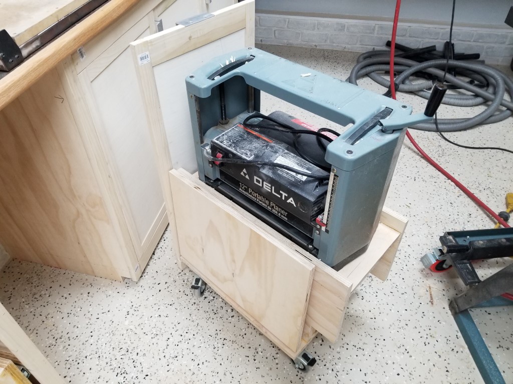
Planer Cart
(I’ve had this built for a while now, but I’m catching up on documenting shop progress tonight)
A while back I got an old Delta ‘Portable’ power planer at a garage sale; it’s helped out in a few projects already so I thought it deserved it’s own spot in the shop design. The planer requires a fair amount of space for it’s infeed and outfeed to keep the material flat, however the planer isn’t used enough to justify keeping it out on the workbench permanently. I also wanted to avoid the need to lift it out of a cabinet, so with this in mind I came up with the cart below that integrates with the cabinets. The cart rolls on double-locking casters and has folding infeed/outfeed tables that align with the planer’s table when upright. I used ‘drop leaf’ style hinges/supports to allow the tables to lock in place.
The ‘dead’ space inside is currently holding the router and router bits; I may convert this to a drawer at some point. When the cart is stored it just looks like any ordinary cabinet door.


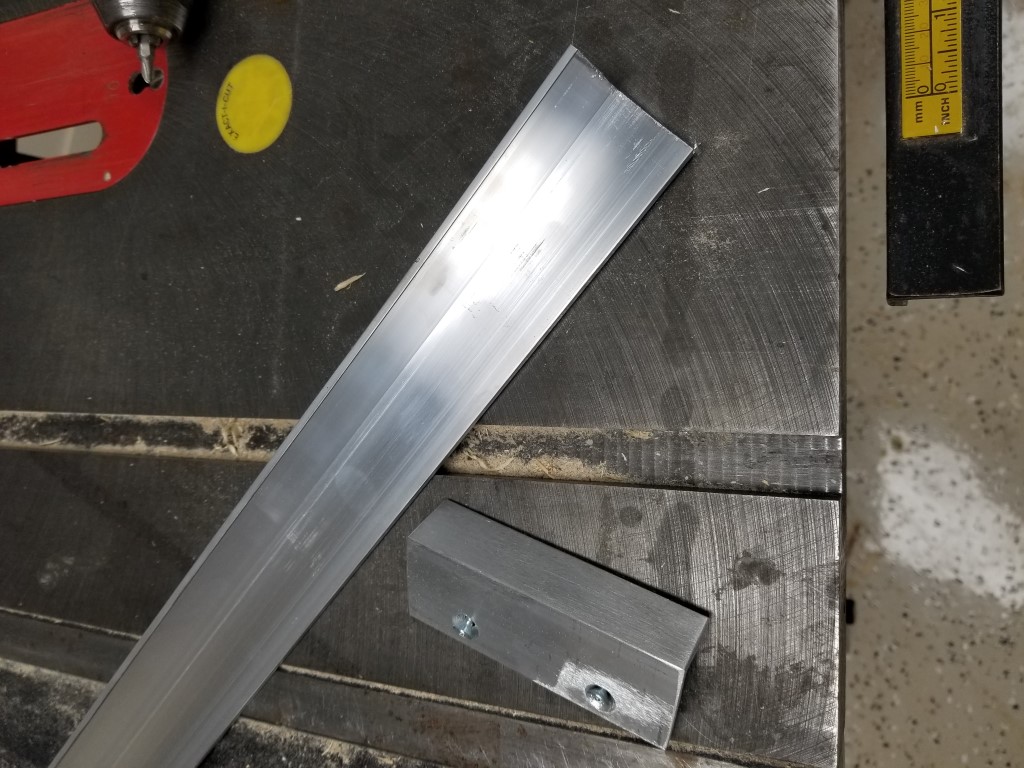
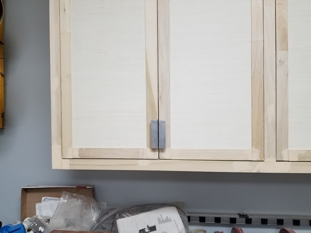
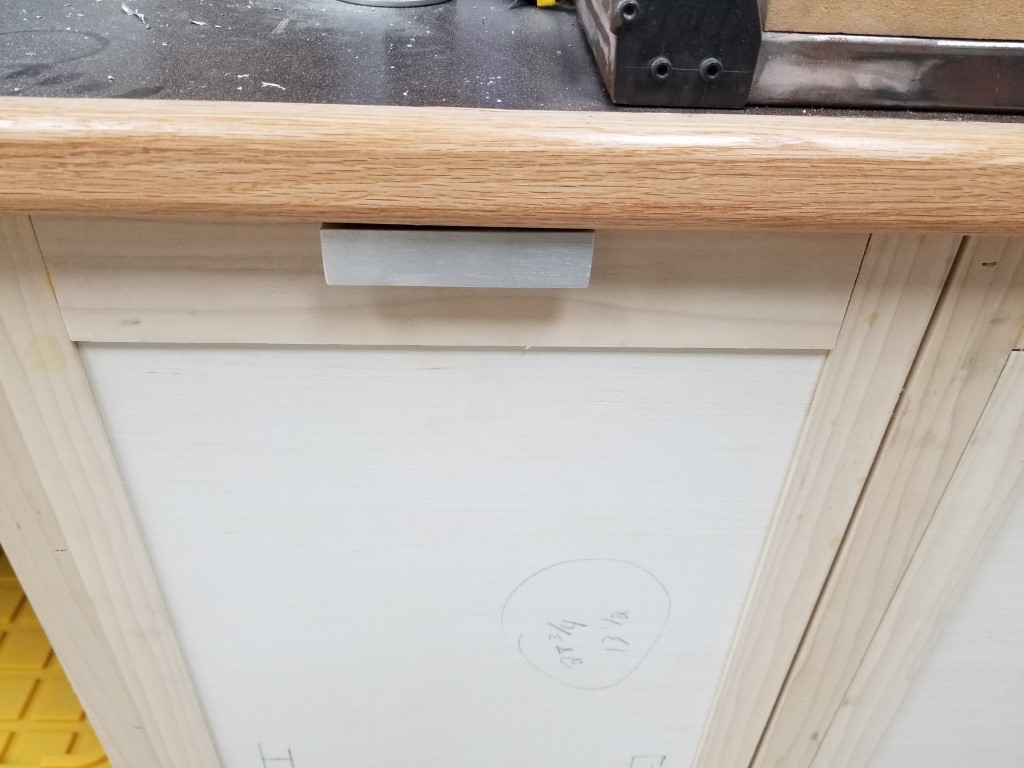
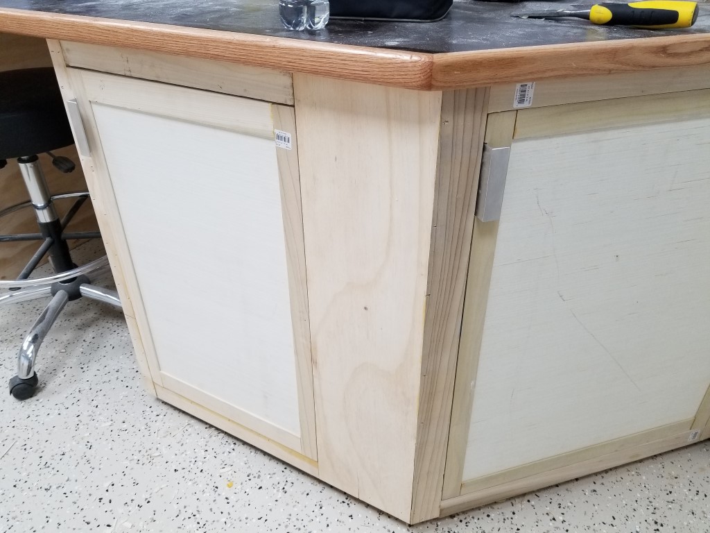
Cabinet Handles
Over the last few nights I’ve been working on handles for the cabinets. The handles are 4″ sections cut from 1.5″ aluminum angle. Before cutting to length I ripped ~1/2″ off of one side of the aluminum so the handles weren’t too wide. This was my first time cutting aluminum on the table saw, it was very quick and effective but also shot scalding hot aluminum chips in every direction and sounded like a Pterodactyl being fed through a wood chipper.
Since I may add/change cabinets in the future I wanted to make sure that I wasn’t locked into a particular brand/model of handle that could be discontinued, by making my own with standard materials this isn’t a problem and the cost was also kept to a bare minimum.
Once all the sections were cut to length I sanded the rough edges and drilled/countersunk holes on the drill press. I made a quick fixture with clamps and wood blocks to get the holes consistently located. To attach the handles to the cabinets I chiseled out a 1/8″ recess and then attached the handles flush with the door edges.
I’m undecided on whether these will keep their current ‘brushed’ looking finish or whether I’ll polish or paint them. I’ll decide that when the time comes to finish/paint the cabinets.
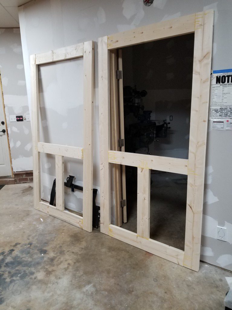
Sliding Doors
The shop floor plan allows for a large opening between the ‘far’ end of the shop and the auto repair/bus area. This will allow tools to be easily shared between both spaces; during a big auto project the repair bay can become an extension of the workshop. The opening is also big enough to bring in the front or rear of a vehicle if ever needed. When auto projects aren’t underway though I’d like to have doors cover this opening to prevent dust/mess from wood/metal project leaving the shop area and to save on shop heating/cooling costs.
The size of the opening presents a problem – swinging doors would have to swing ‘out’ of the shop to avoid hitting cabinets, and the large sweep would require moving anything parked on the garage side out of the way temporarily, kind of a hassle. To avoid this problem, sliding doors made the most sense.
The shop build project is being run with the materials cost set to minimum and the end-product quality set as high as is practical. This sounds unrealistic but is actually possible with the trade-off being time; it’s not a problem though since I count this as hobby time and there’s no particular deadline. The sliding doors are a great example of this – sliding doors and hardware are outrageously expensive compared to the raw materials cost. Building my own also gives me full control, in this case I wanted to avoid the farmhouse/barndoor/rustic look in favor of cleaner traditional/modern look. Over the last few weekends I’ve built the doors and tracks below, key points:
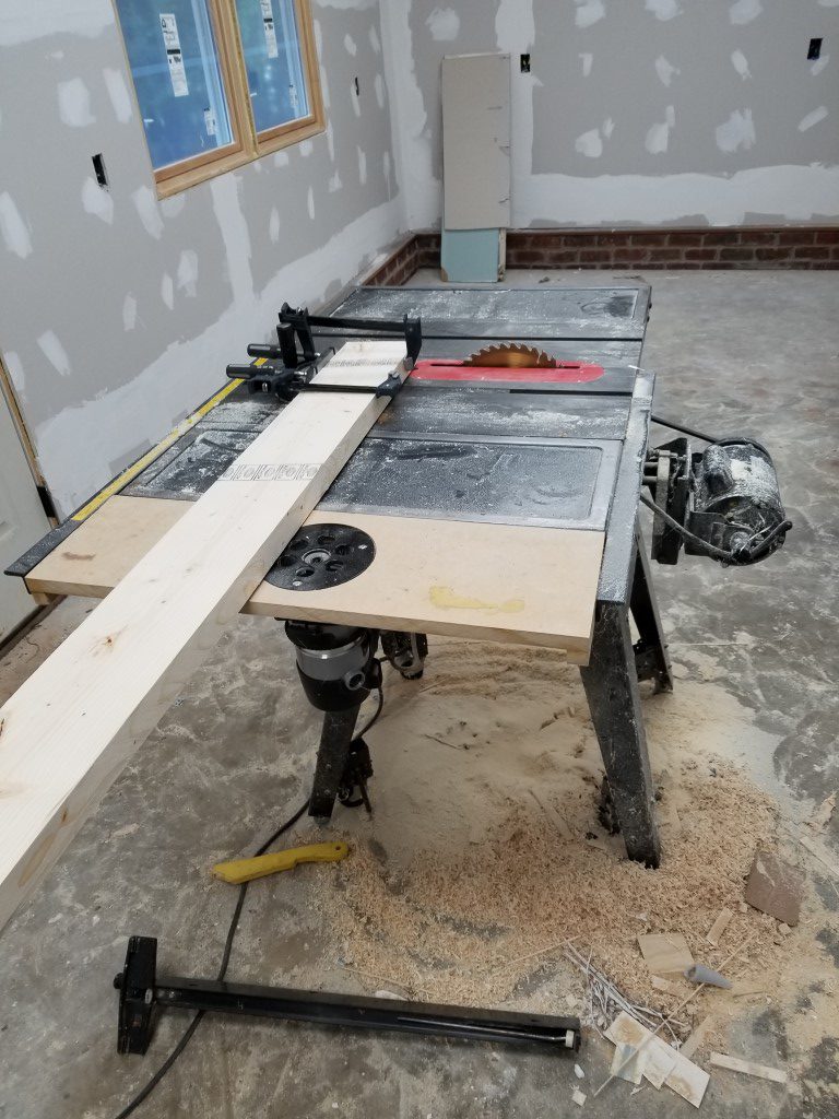
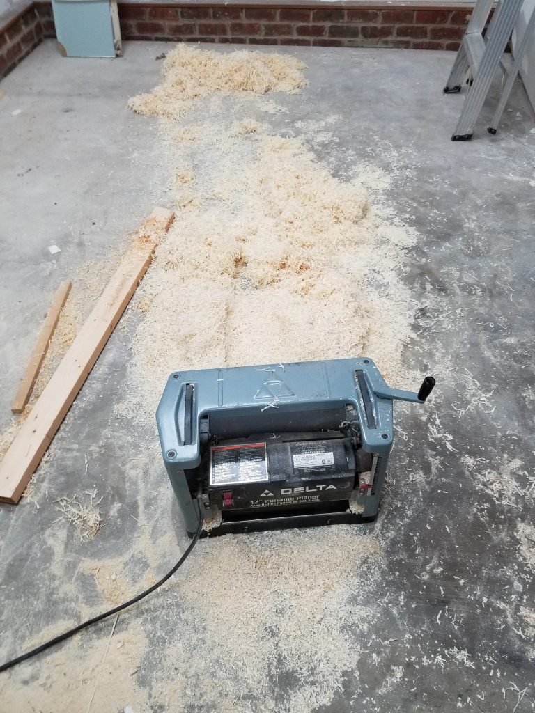
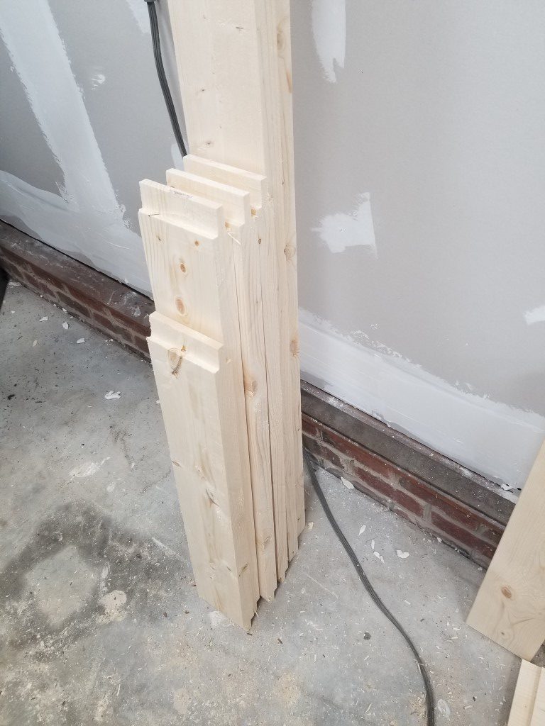
- Door frames from 2×6’s, planed down to standard 1 3/8″ door thickness
- Mortise and tenon joints connect frame pieces (tenons via table saw dado stack, mortises via router and chisel)
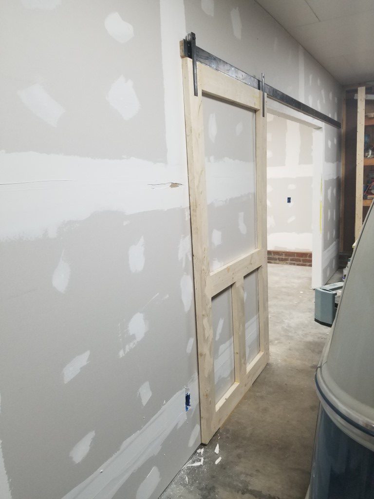
- Slide rail is two 3/16″ x 3″ x 10′ flat bar sections welded in the middle.
- Door bracket pins turned and threaded on lathe then welded to brackets.
- Aluminum rollers turned on the lathe, held to the brackets using standard 608 skate bearings.
- Brackets recessed into door frame and secured to the doors with studs welded to back side for a completely smooth front.
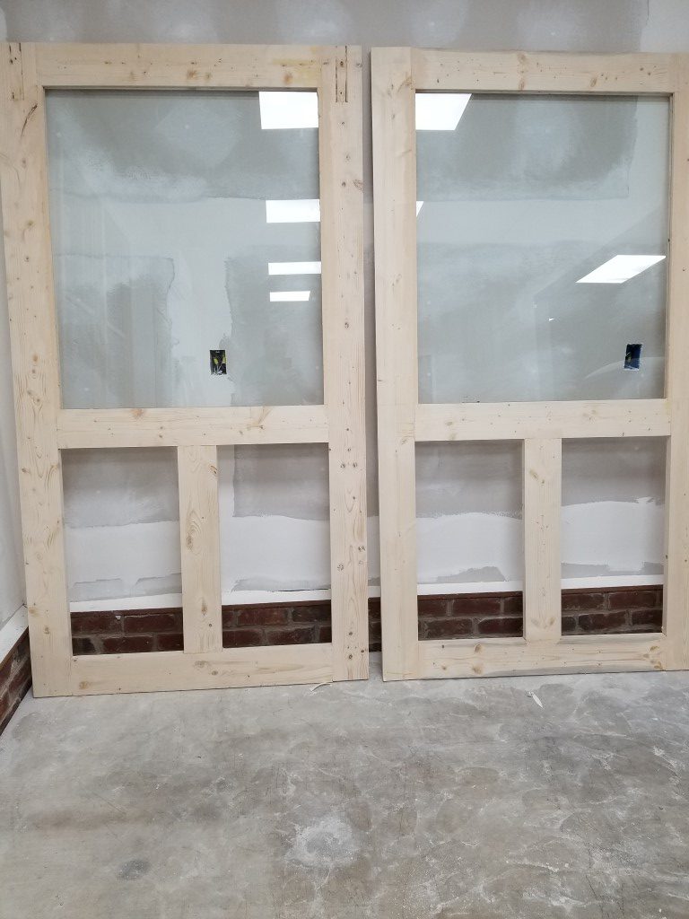
- 1/4″ Tempered glass sourced from local glass shop.
- Groove along bottom of door and small bottom bracket keep door located against the wall and limit inward overtravel.
- Roller to door top spacing and roller flange width prevent door from lifting/falling off rail.
There’s a good bit of finishing work still left, but I’m happy with the results so far.


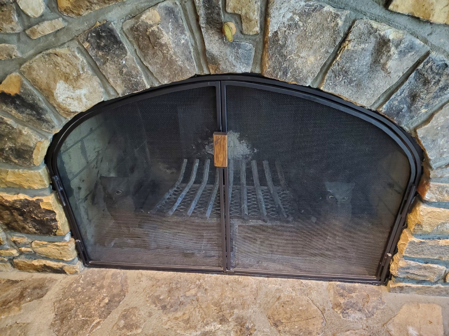
Fireplace Screen
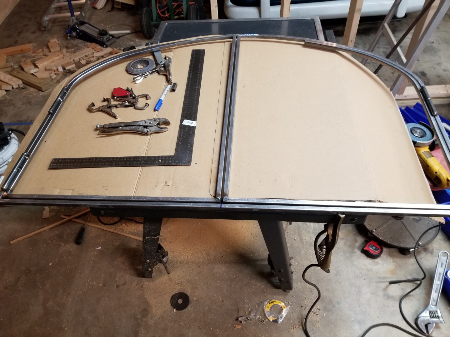
The new place has an open stone fireplace which presents two problems: #1 When there is no fire, the cats could access it and track soot and ashes around, and #2 when there is a fire there’s no protection from sparks, shifting logs, etc. The previous owners had a free-standing screen – this wasn’t left behind and didn’t address either problem well, so I decided to make a custom screen/door to enclose the fireplace. This started by bending an outer frame from 1/2″ square tube to fit the inside of the fireplace opening. I did this in several segments and welded them together.
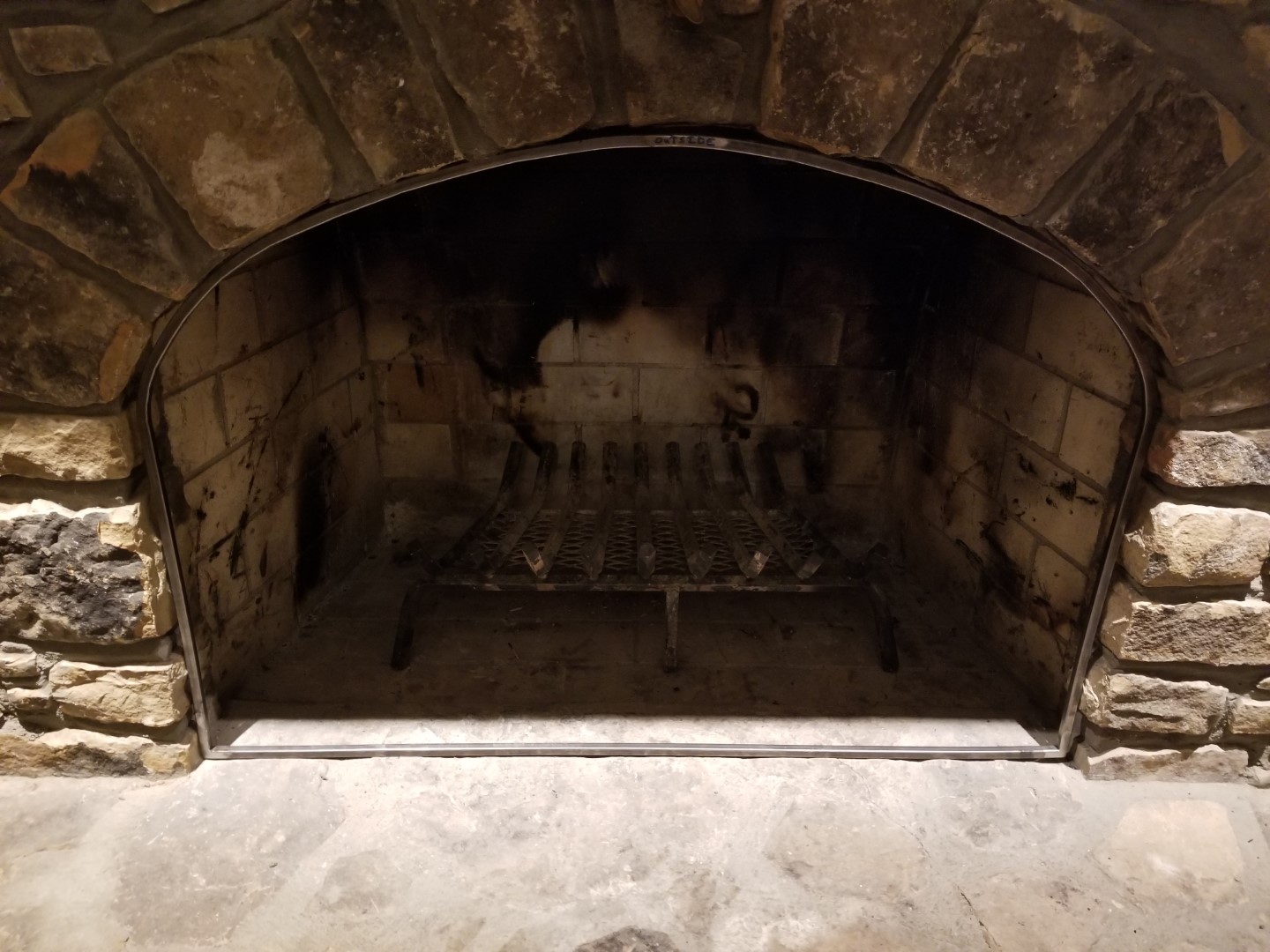
Once the outer frame fit well I made two doors to fit inside. The doors attach to the frame via hinges I made from scrap steel tubing and round bar – when fully open there’s just enough room to lift the doors off the hinges if ever needed for cleaning/maintenance.
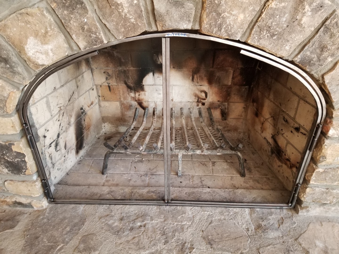
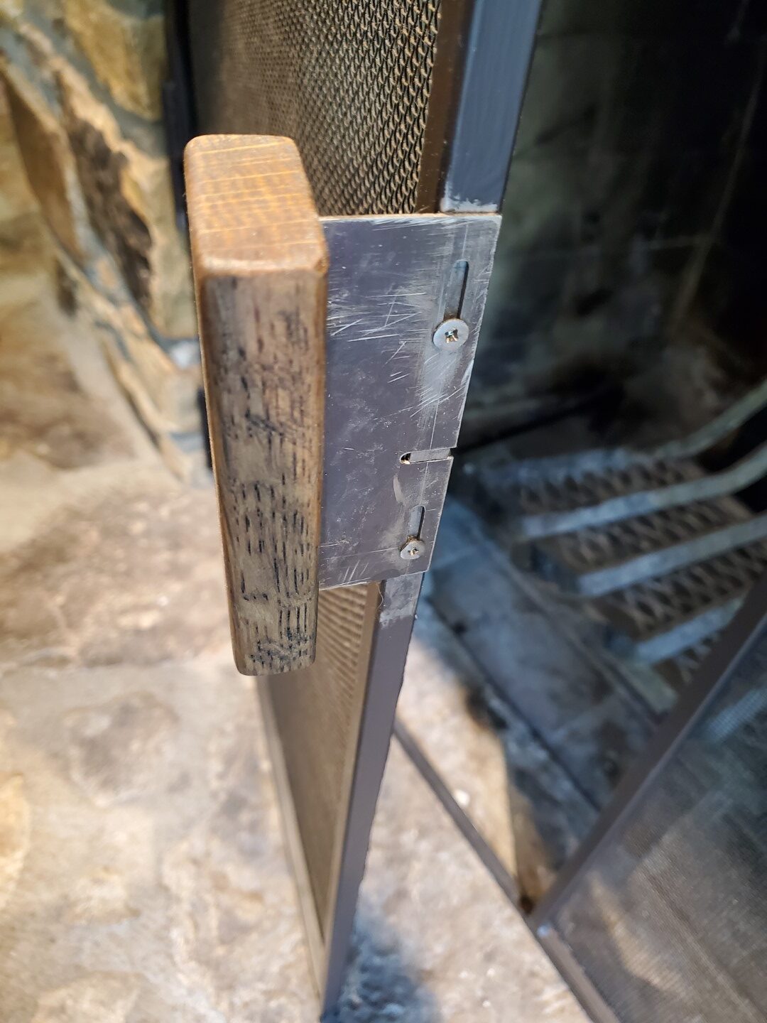
The left door locks to the bottom of the frame via a round bar that slides up/down inside the door frame. I made a tab on the end of the bar that protrudes through the frame and engages with the handle that’s attached to the frame with slots; it also has a tab to keep the right door latched in place. Since stone is irregular there were inevitable gaps, these were filled by tracing the gap onto cardboard and then these strips of cardboard were used as templates to cut out sheet metal strips. The sheet metal strips were secured to the back of the frame with self-taping screws; since the surfaces are rough this also locked the frame in place. The sheet metal was then sealed to the stone with furnace cement and all of it painted with high temp paint.
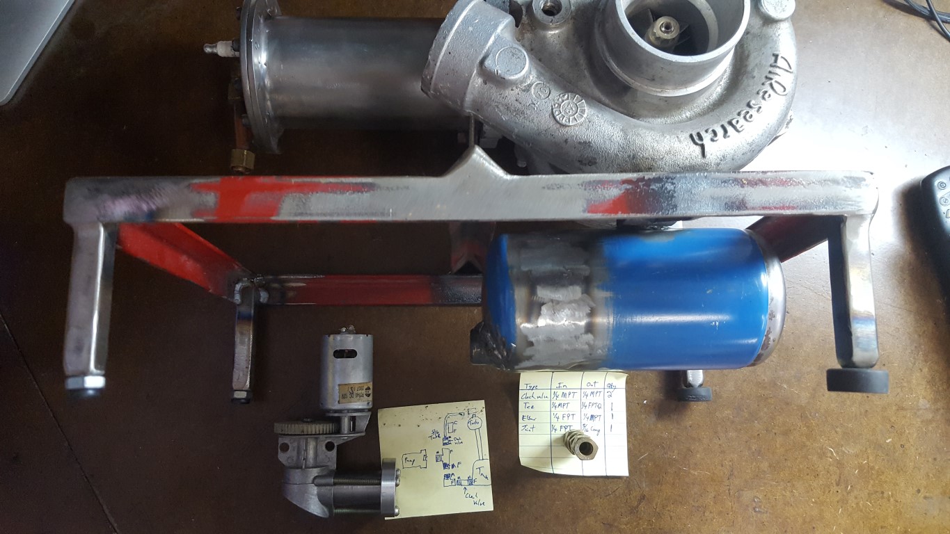
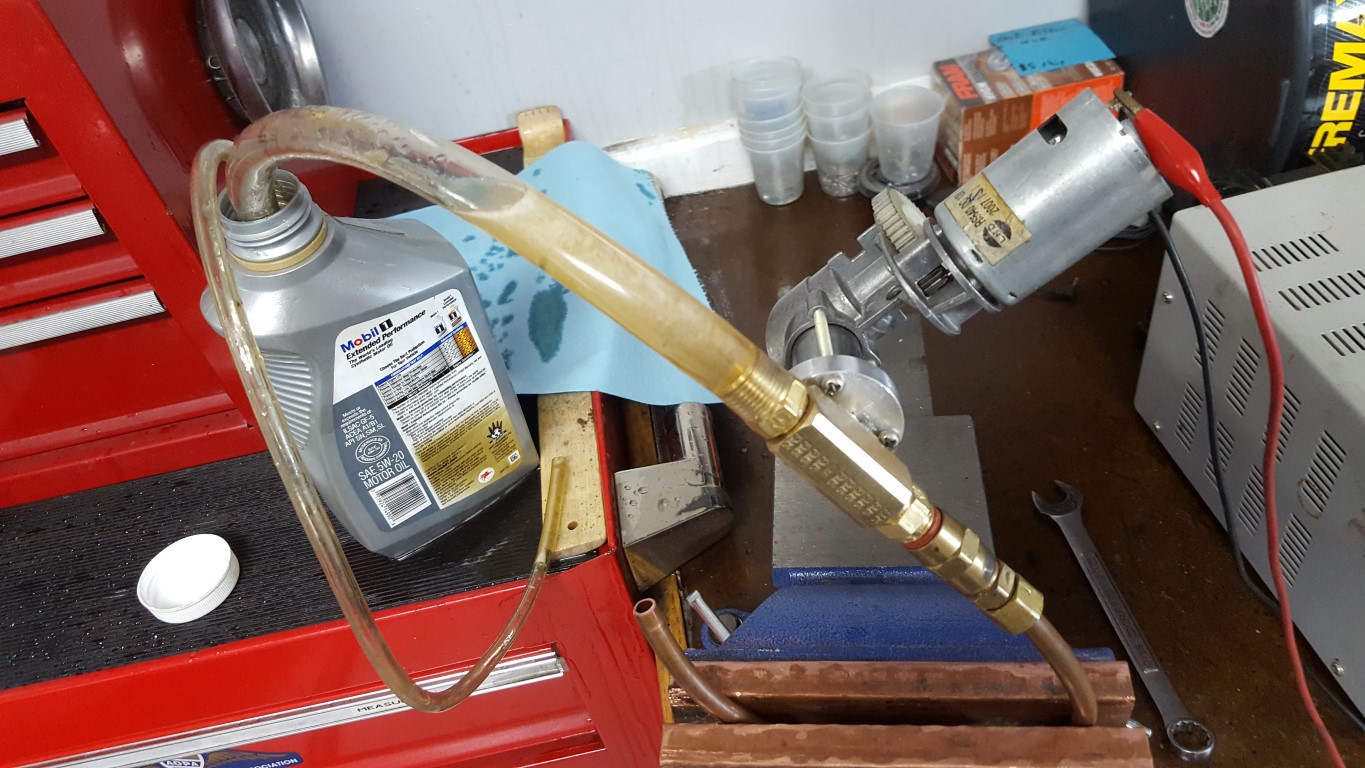
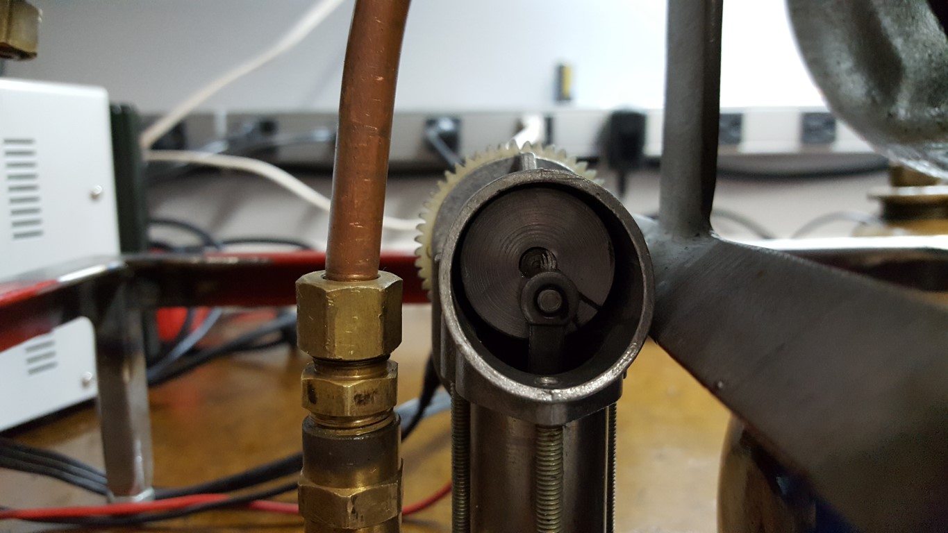
Jet Engine Oil System – Test Run
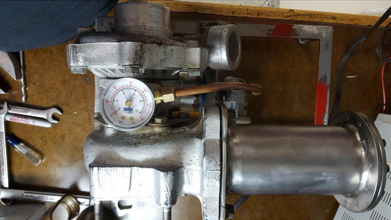
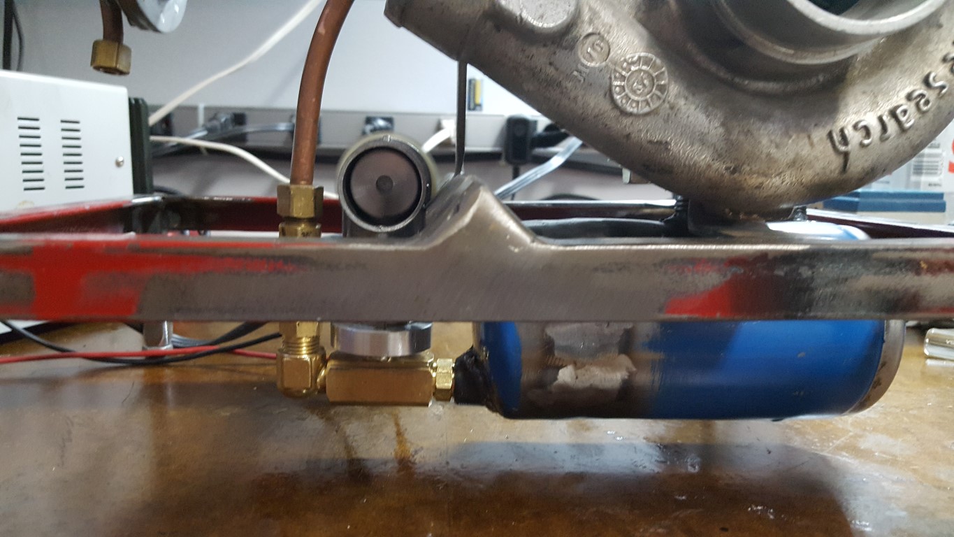
Tonight I tested the oil pump – it worked so well that the pressure blew off one of the plastic tubes I was using for testing and sneezed oil over everything. After I cleaned up the mess I connected it into the system and did another test run. The extra resistance of the oil passing through the turbo bearings caused the pump to stall out on the first attempt. The pump was originally designed to move air, so it’s not surprising that oil was too much of a load. To remedy this I made a new crankshaft for the pump on the lathe with as short of a ‘throw’ for the piston as possible. With the shorter throw, the pump is moving less oil per rev which reduces the load and prevented the motor stall. After this change it successfully ran continuously and held an average pressure in the system of about 75PSI, right about where it needs to be. To keep things simple I don’t have a bypass or pressure regulator in the system; because of this the pressure gauge flutters with each pump stroke but this doesn’t hurt functionality.
The motor draws about 5A, at 12V this is ‘only’ 60Watts and is about the same or even a bit less than when it was an inflator pump. Since it will now be running for longer time periods though I need to keep an eye on the motor temperature. I also need to protect the plastic gear from the (eventual) heat of the combustor above. To address both of these problems I’ll likely make a heat shield for this area as well as add a cooling fan.


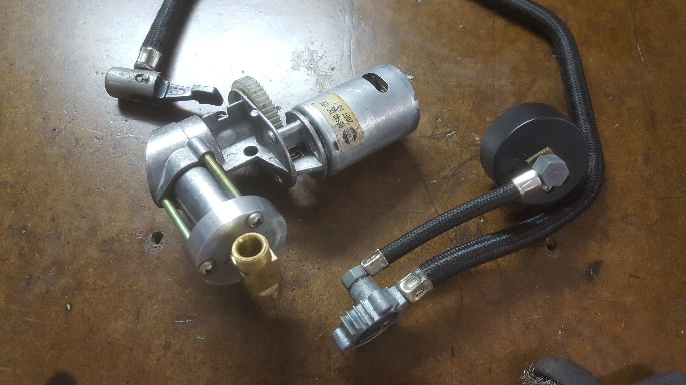
Jet Engine Oil System
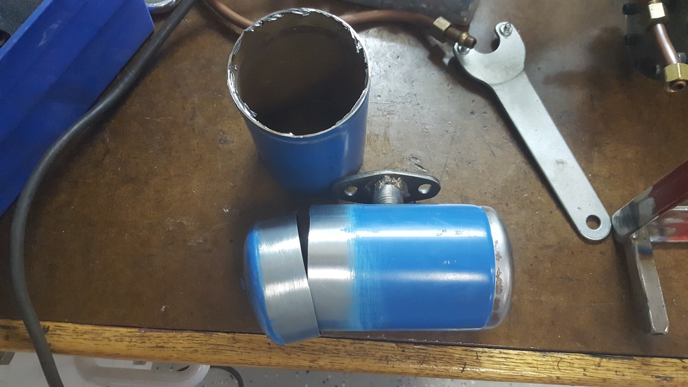
This weekend I resumed work on the jet engine project. When I last left off I had just completed the frame and mounted the turbocharger/combustor. I had also fabricated an oil tank out of an old propane tank and mounted it under the turbo, but had hit a bit of a wall with what to do for an oil pump. There are electric oil pumps available, but basically all of them would be overkill for this application. Also, since this is a hobby I’d much rather put in the time to make something custom vs paying for parts. Turbocharger jet engines have been done by many others, my approach with this is to see how compact and well packaged I can make one – that doesn’t happen by bolting together a bunch of off-the-shelf parts.
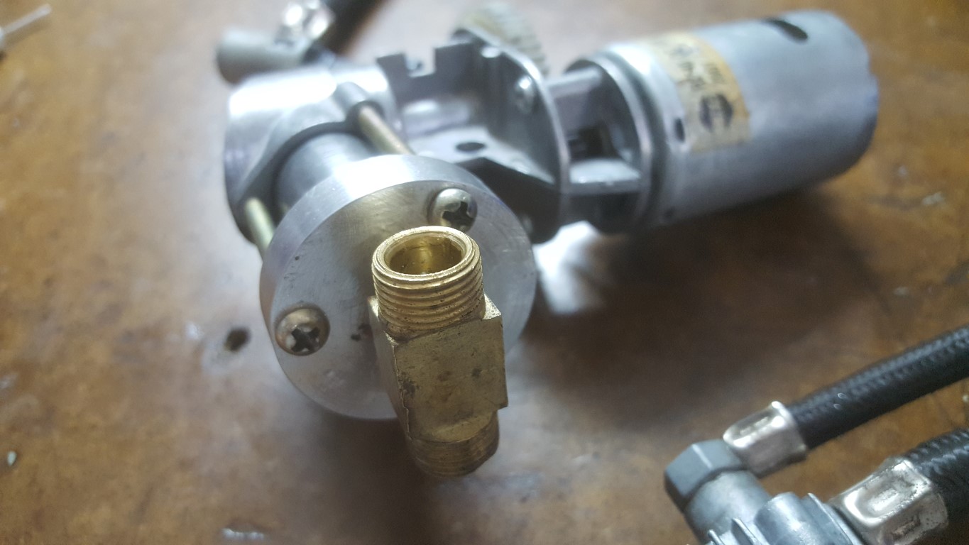
I had considered using the bus’s old oil pump, but this created more problems than it solved (connection of inlet/output pipes would be a challenge as would driving it and selecting a motor). Today after a taking a fresh look at it I realized that an old 12V tire inflator pump that I had could be adapted to work. The plastic casing had broken, but the ‘guts’ were all metal and should hold up to oil pump duty. The only problem was that the cylinder head of the pump had no way of connecting an inlet pipe – being designed for air, it just drew in air from a small hole. To fix this, I made a new cylinder head on the lathe with one large hole in the center. A tee fitting screws into the head and I’ll put a check valve on each side. This larger single-hole head should also help compensate for the increased load of pumping oil, much thicker than air. Once I start running oil through it I may have to make some tweaks to avoid overload (lower voltage, thin oil, etc) but this at least gives a path forward for experimentation.
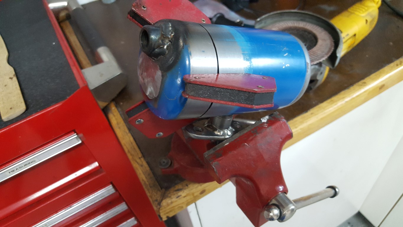
I also shortened the oil tank to make more room underneath for other support systems and made a threaded port on the lathe to weld into the tank to connect the oil pump. The welds aren’t the greatest looking, but are leak-free and that’s what matters – they should clean up OK after some grinding. For now the whole project is in fabrication mode, but once everything is in place and working I’ll go back and do body/paint work on all the parts to make it look nice too.