E-Ink Bank Calendar
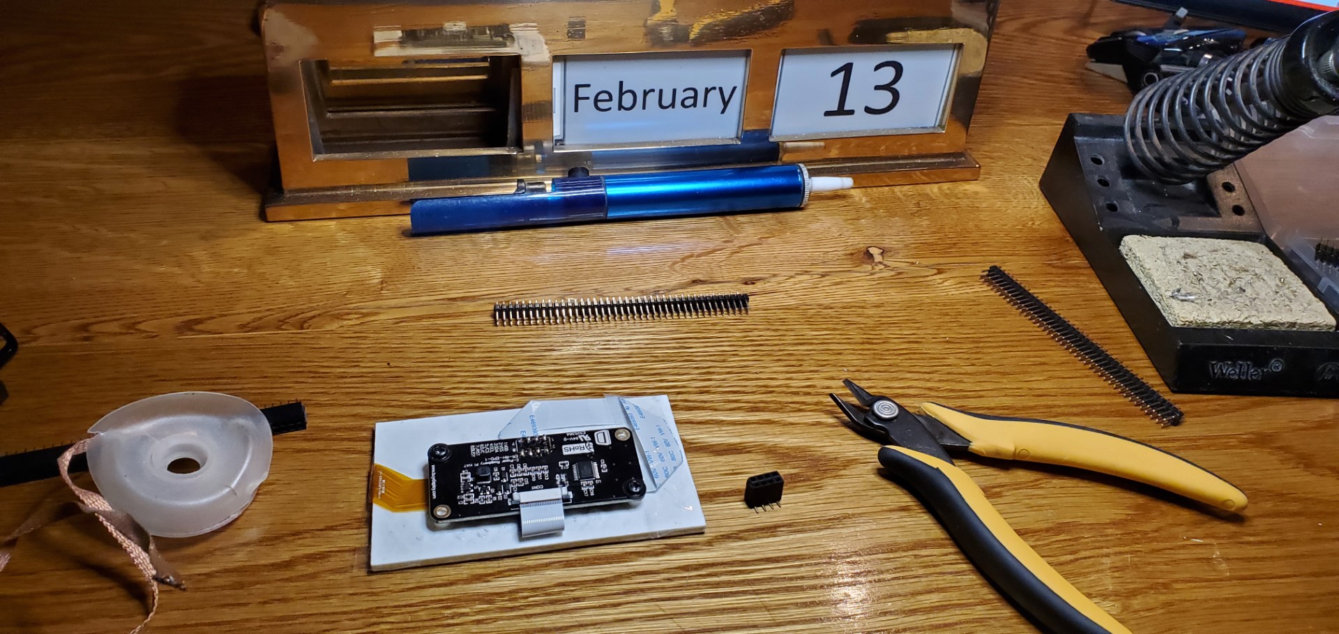
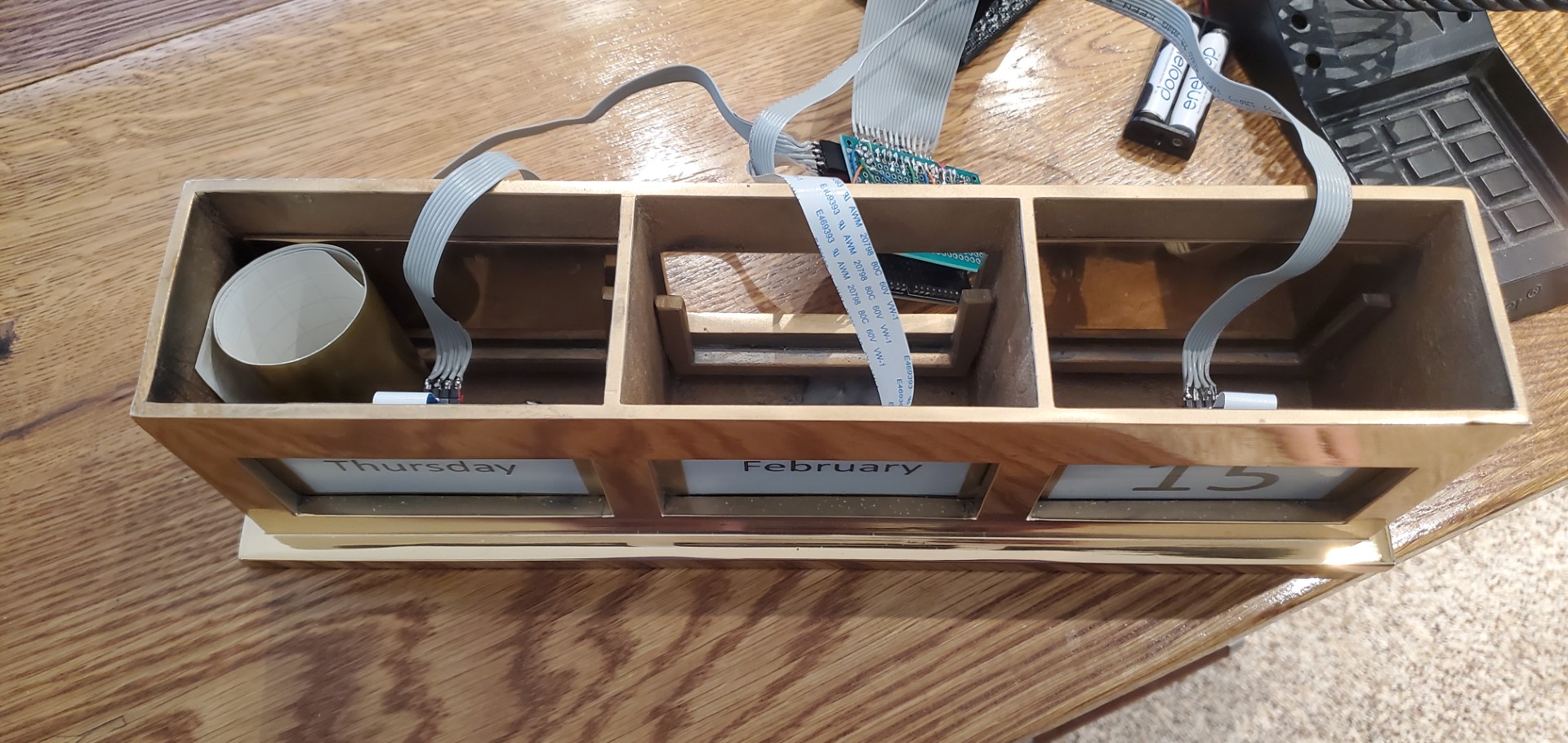
I was recently given a brass calendar frame that normally holds a collection of small cards corresponding to the date. The top lifts off and the cards are re-arranged to display the day’s date. I decided to automate it with the following:
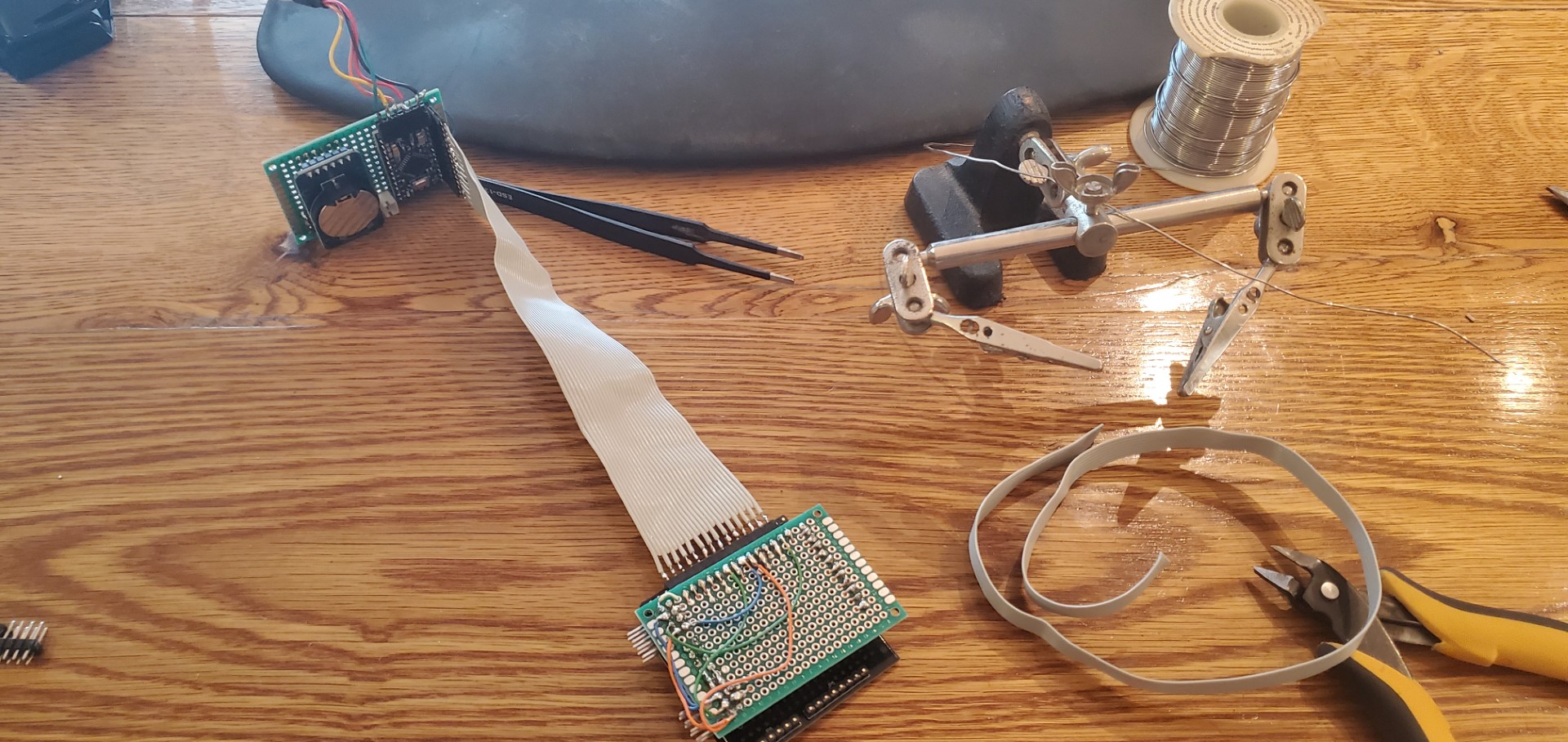
- Arduino Pro Mini, ATmega328P microcontroller board (1x) Main controller for the system, runs the code integrates everything else.
- DS3231 Realtime Clock module (1x). This keeps track of the time/date. It has its own small battery to stay running while main system power is off.
- 3.7″ Epaper displays(3x).
- Epaper connector board (2x) – mainly just a breakout board for the epaper display’s ribbon cable, but it also handles signal buffering and making a few weird voltages that the epaper display needs.
- Epaper interface board (1x) – same as the connector board, but also has onboard SPI RAM and MicroSD card slot.
I’ve designed many various electronic circuits/devices, but this is the first I can recall where the power budget matters a lot. The power usage would always be low with these devices, but I wanted to avoid a scenario where it’d need a wall wart plug – the goal is for it to run a reasonably long time, a year or so, on a rechargeable battery. The magic of the e-paper displays (other than having the image very close to the surface, looking more like real paper than a display) is that they can be completely powered off and still retain their image; that’s a huge head-start to low power usage. This left the micro-controller as the main risk for power consumption, however with careful use of interrupts I think I’ve optimized this. The sequence, which happens every night at midnight, is:
- DS3231 asserts its alarm pin
- The alarm pin is connected to an interrupt on the ATmega328P which has been configured to wake the microcontroller and begin code execution.
- The microcontroller communicates with the DS3231 over I2C to read the new date and resets the alarm for the next midnight.
- The microcontroller reads the SD card to lookup graphics corresponding the 1st display based on date, this is read into RAM and then shifted to the epaper display. This repeats for each display. (The controller inside each display goes through its own routine for the physical screen update that causes the screens to flash Black/white several times)
- The microcontroller goes back to sleep mode, no code execution and extremely low (almost no) power usage until next midnight.
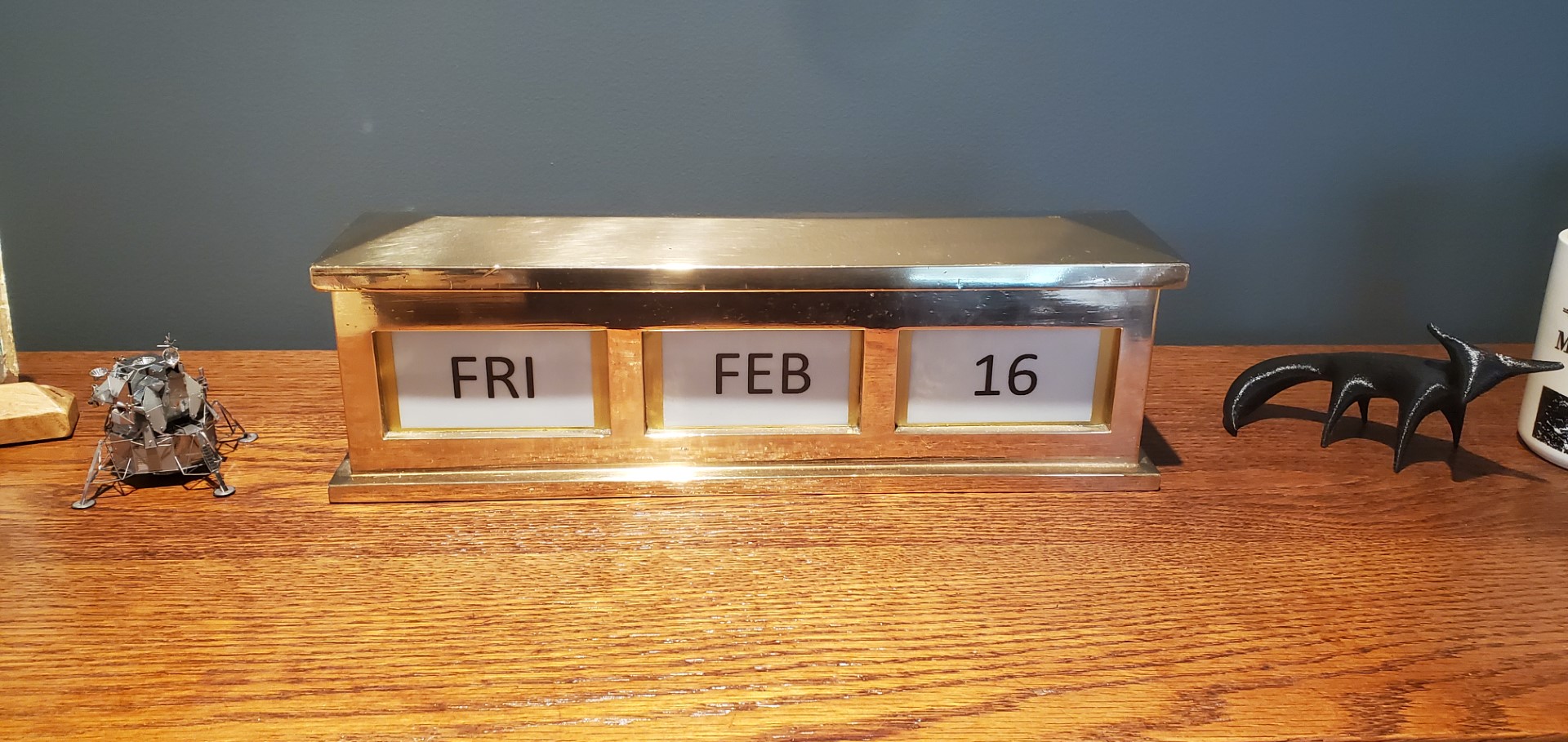
With this sequence it’s very nearly off the vast majority of the time, only the small clock battery on the DS3231 module keeps it going; then everything else only wakes up for a few seconds at midnight to update the screens. Time will tell how efficient this is, but it should be as good as theoretically possible. The DS3231 battery is meant to hold the time for ~10yrs, when the main battery is depleted the screens will stop updating but time won’t be lost – proper date will be displayed on the first update after a recharge without any need to set the time/date.
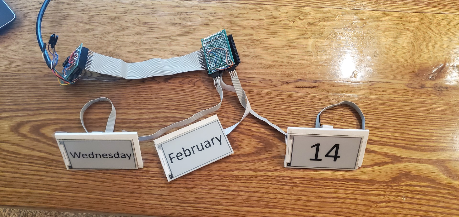
The software for writing to the epaper displays leans heavily on the example provided with the displays, but the example assumed only a single display. Since I had limited IO pins and there was no need to update displays simultaneously I modified the library to accept a display index for each function. With this, I was able to put everything on the same SPI bus and share the SD/RAM between all displays, the library just only asserts the chip select line for the display being updated during the overall update sequence.
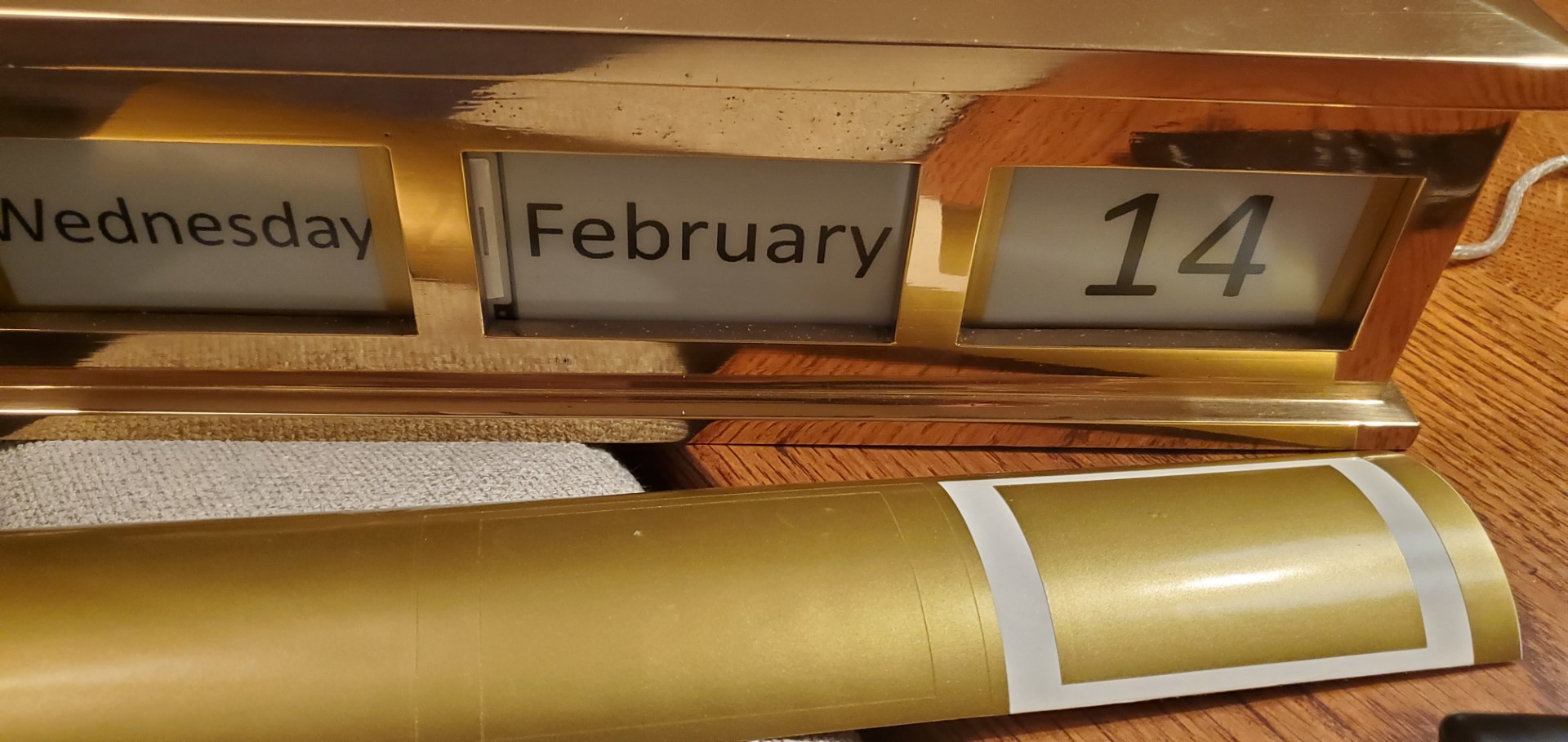
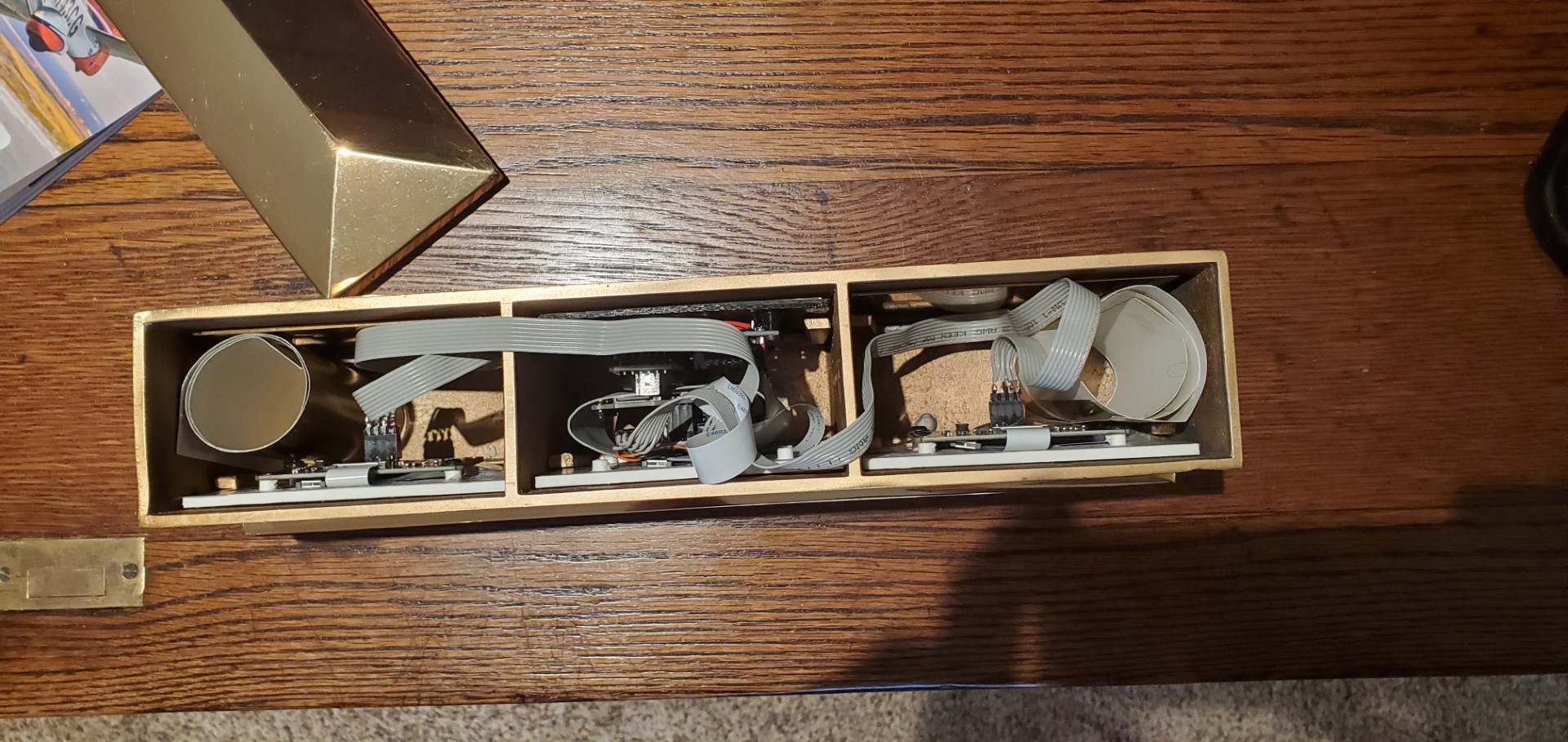
Mechanically, each display is mounted to a 3D-printed plate that pads out the display to the right dimensions, the plate also has screw bosses where the connector boards are mounted. Although the display sizes were very close to the right size, it was unavoidable that some non-displayable area of the panels showed through the front of the calendar frame. To make this look better I made some vinyl frames in a metallic brass/gold color to cover these margins.
(Note: Dates don’t necessarily correlate with actual time/progress since the date was adjusted many times during testing. I also tried several different fonts/styles before deciding on the “FRI FEB 16” format.)
| CPU PIN | Function | Connection |
| 0 | Serial Prog | Prog cable |
| 1 | Serial Prog | Prog cable |
| 2 | ClkInterrupt | RTC |
| 3 | RAM CS | Epaper #1 |
| 4 | EPD2 CS | Epaper #2 |
| 5 | ClkReset | Pushbutton |
| 6 | DateDown | Pushbutton |
| 7 | DateUp | Pushbutton |
| 8 | EPD2 Busy | Epaper #2 |
| 9 | SD CS | Epaper #1 |
| 10 | EPD1 CS | Epaper #1 |
| 11 | MOSI | Epaper all |
| 12 | MISO | Epaper all |
| 13 | LED/CLK | Epaper all |
| 14 | EPD RST | Epaper all |
| 15 | EPD1 Busy | Epaper #1 |
| 16 | EPD DC | Epaper all |
| 17 | EPD3 CS | Epaper #3 |
| 18 | SDA | RTC |
| 19 | SCL | RTC |
| GND | GND/VSS | all |
| VCC | VCC | all |
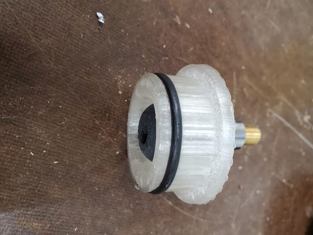
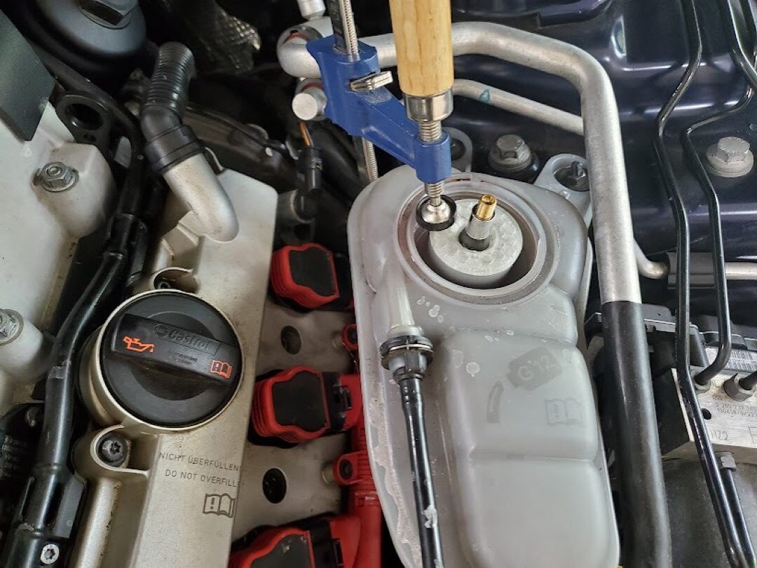
S4 Coolant Leak Tool
I noticed a small coolant leak on my car recently. It wasn’t clear where it was coming from, only that it was somewhere in the front and only occurred after running for some time. To help troubleshoot this I created a 3d printed adapter that interfaced a tire schrader valve to the coolant tank, sealed with an O-ring. An F clamp held this adapter in place and I pressurized the coolant system to a few PSI. This lead to the discovery of a bad O-ring on one of the coolant crossover pipes at the supercharger, which was easily fixed.
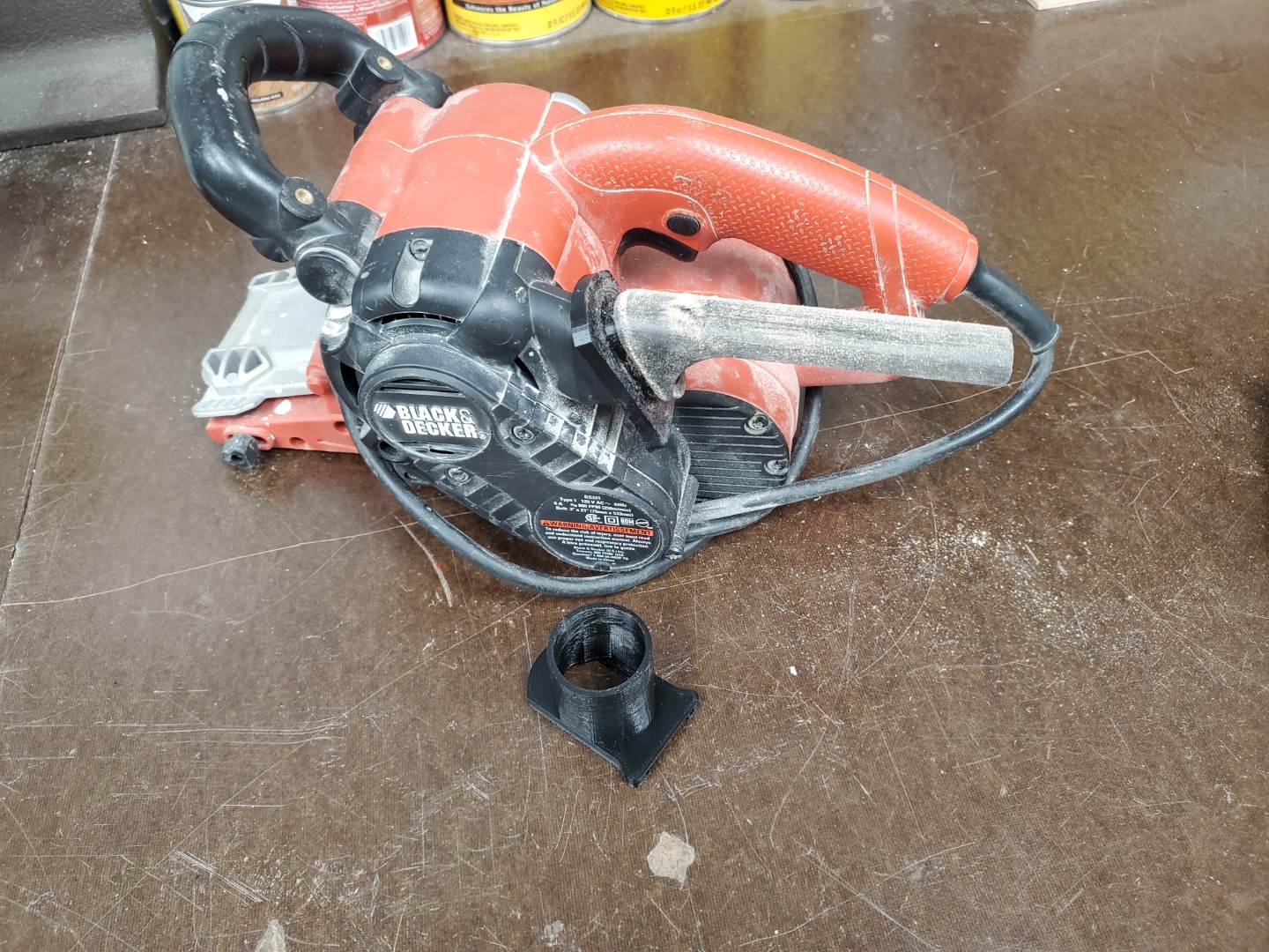
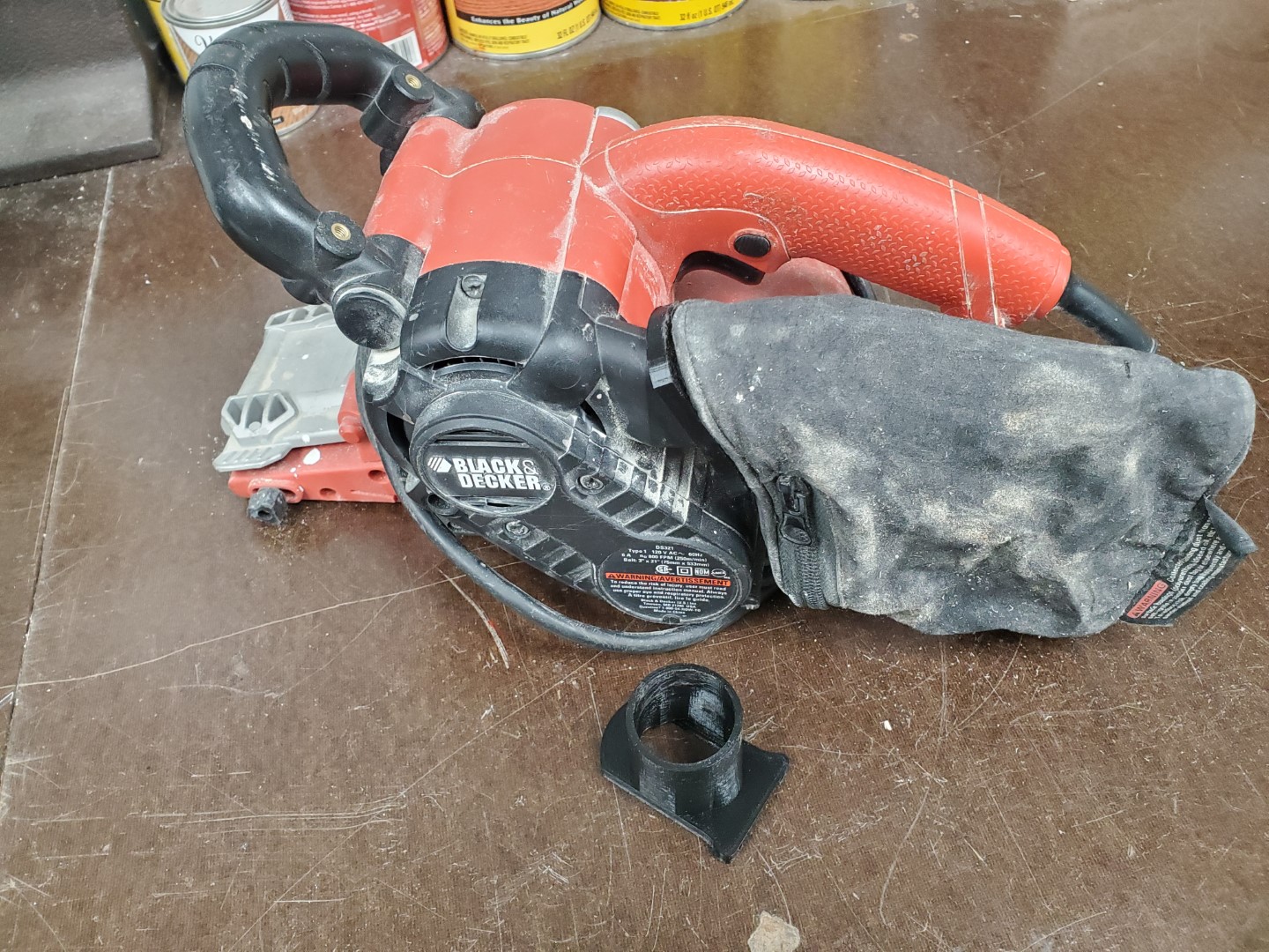
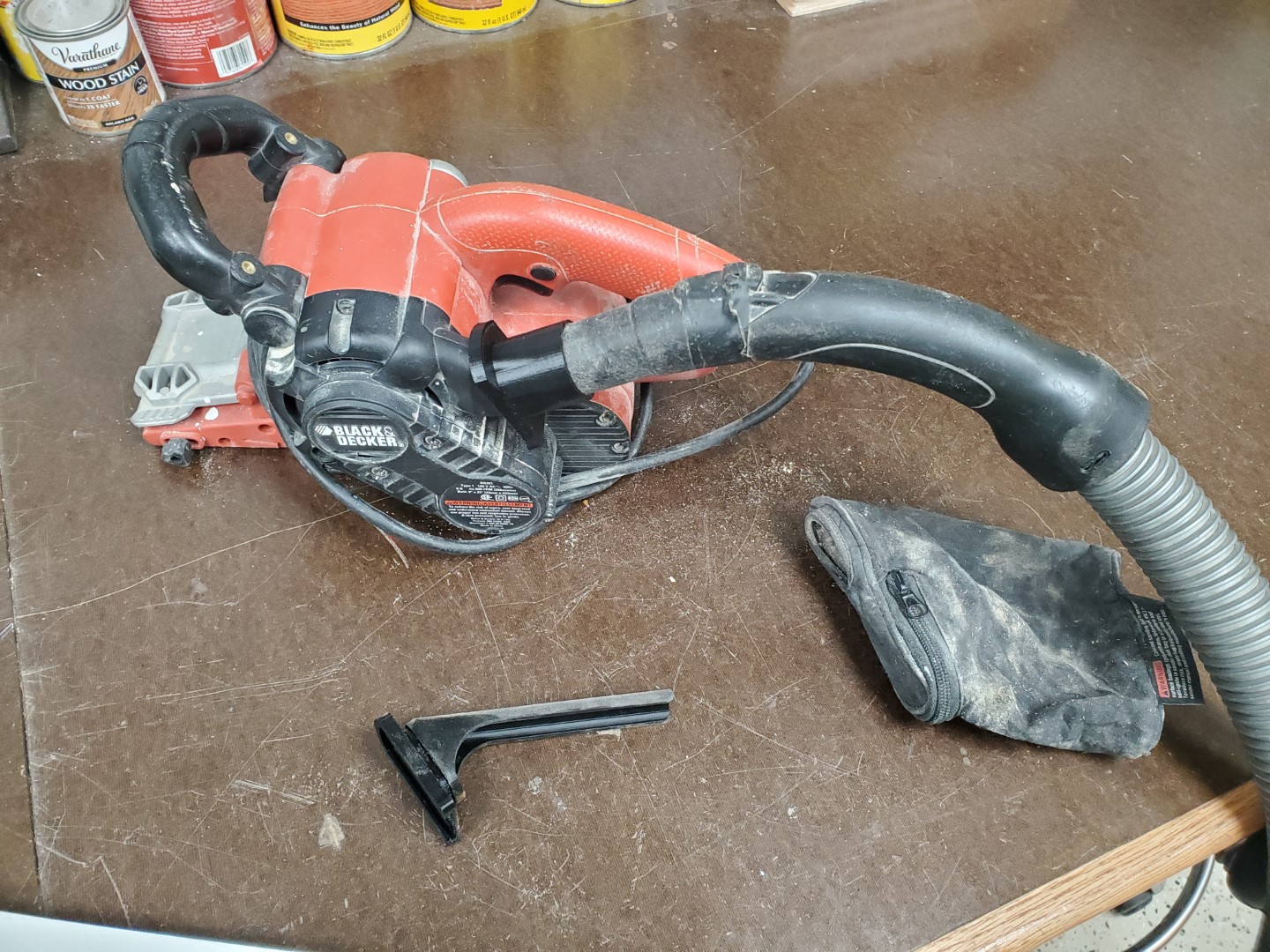
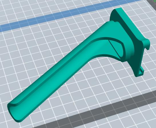
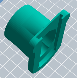
Belt Sander Fix
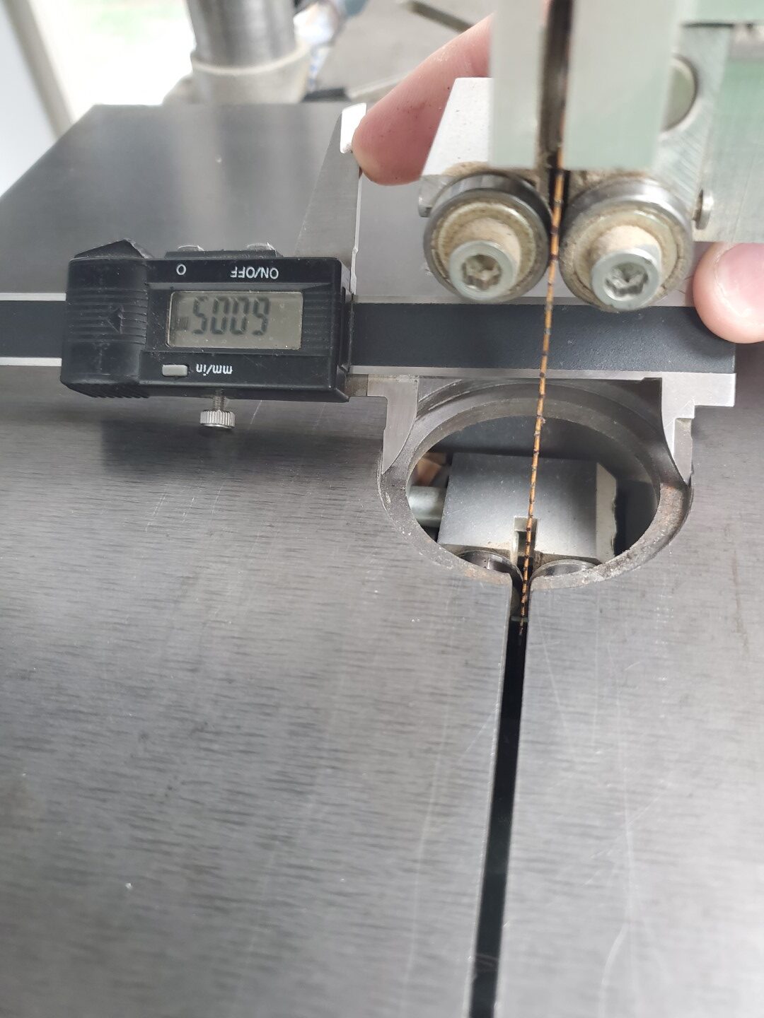
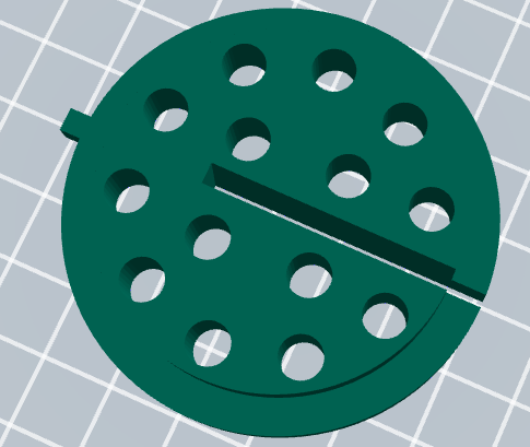
Bandsaw Insert


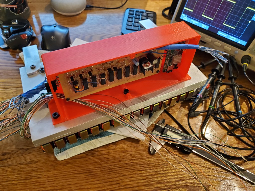
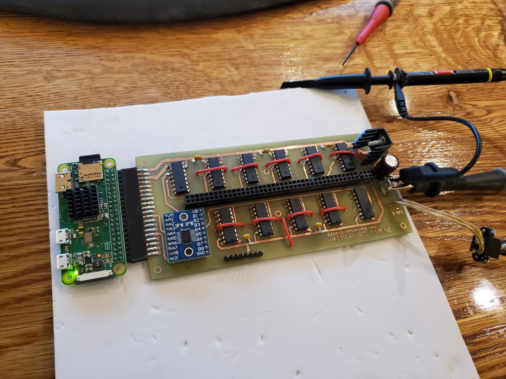
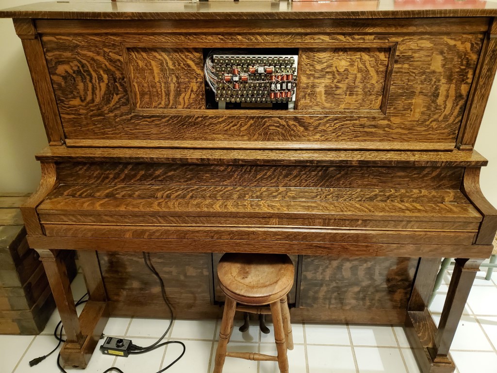
Piano Automation – Valve Control Board Build and Test
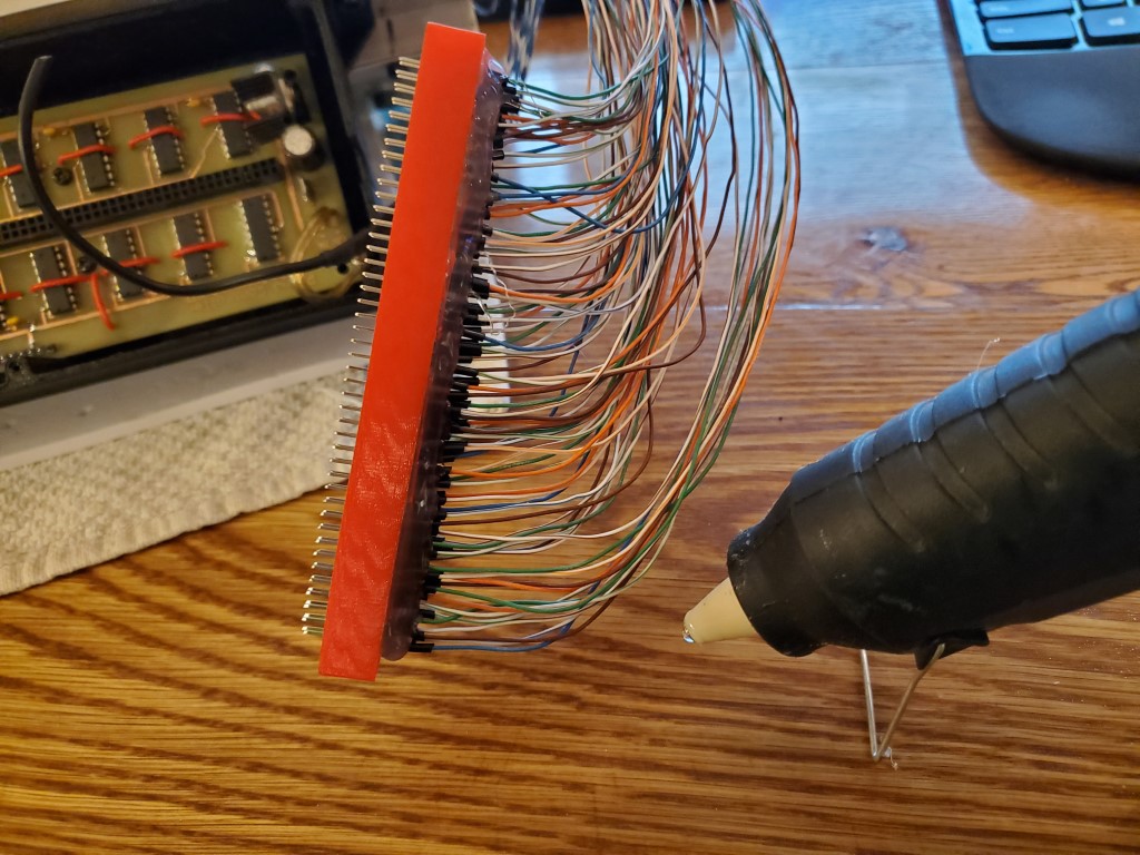
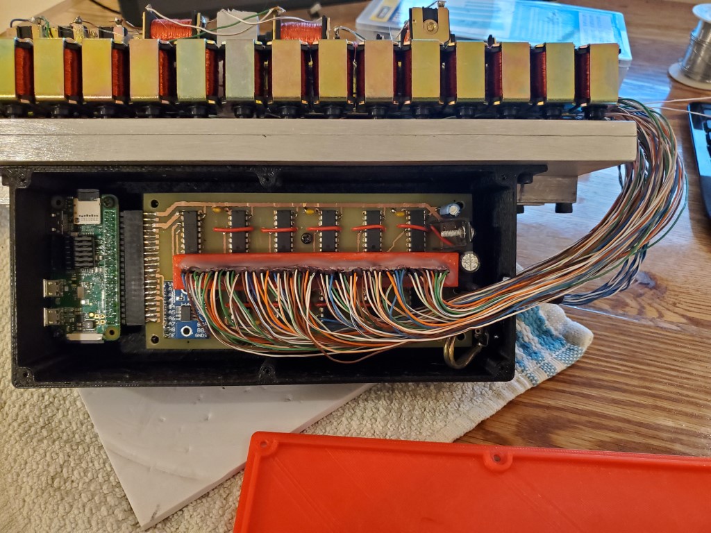
Last weekend I got around to populating and testing the piano valve control board. Unfortunately it did not work when initially powered on, I was able to track this down with a scope to problems with the level shift circuit between the pi and the shift registers. Rather than troubleshoot this farther I ended up re-designing and re-etching the board to replace my transistor array level shifter with an off-the-shelf level shifter sub-board. I also took this opportunity to #1 redesign the solenoid wire connections so that a pin header connection could be used rather than having the wires directly soldered to the board and #2 add a connector to the edge of the board to use the pi’s pin header connection.
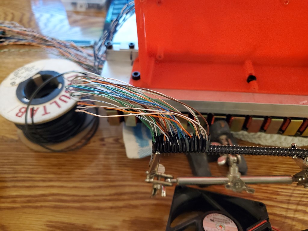
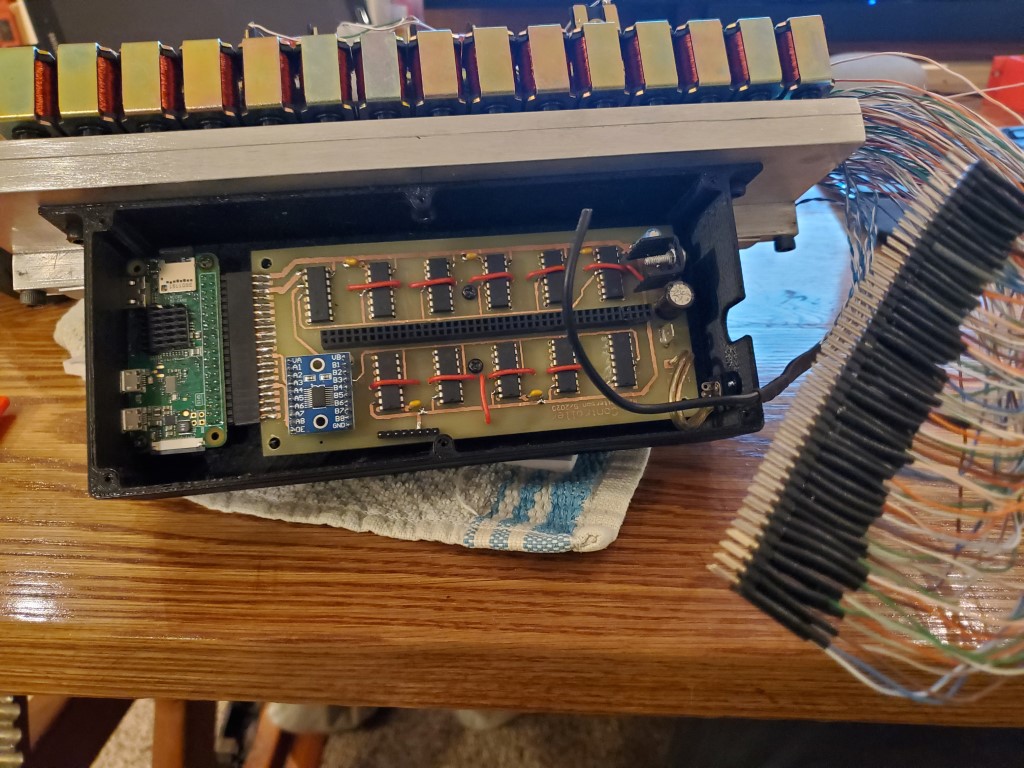
In the mean time I had also created a 3d printed enclosure to hold the board on the back of the valve bank. This was important as it allowed the final solenoid wire lengths to be determined and I soldered all the solenoid wires onto a pin header. I also 3d printed a support ring to stabilize the pin header and hot glued it all together to act as a single strain relieved connector.
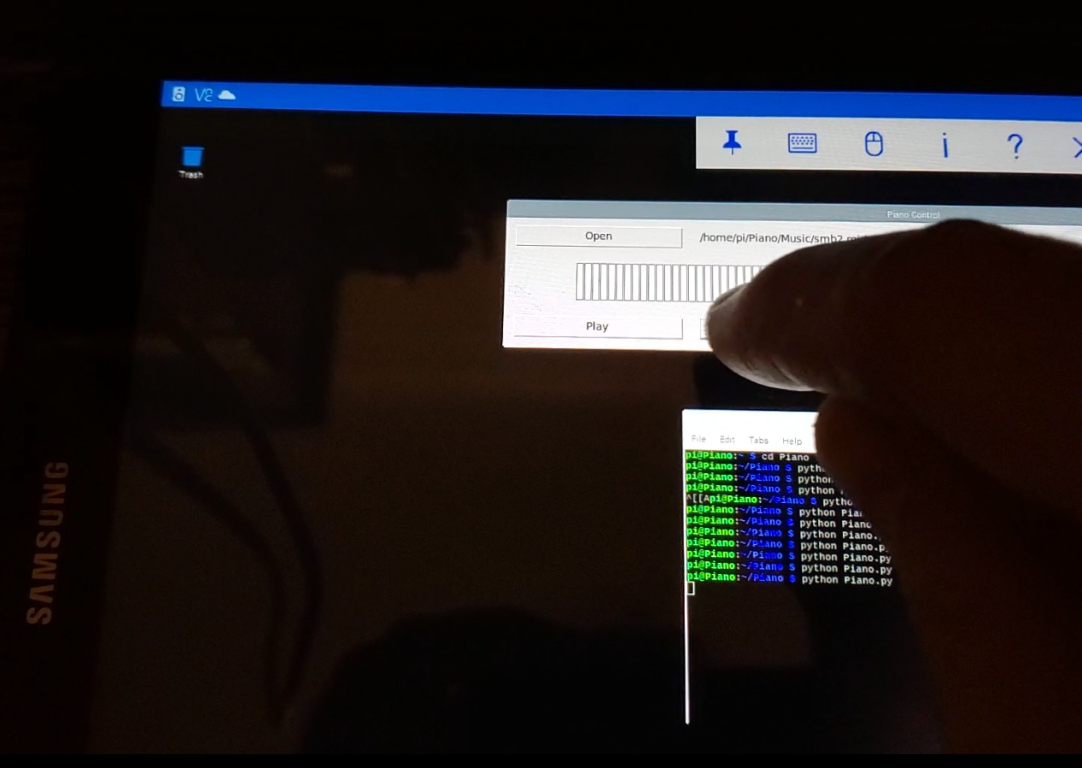
This weekend I was able to finish and test the re-design. All channels seem to be working OK and I’m able to control the piano keys individually from a tablet using a python script. I have some python scripts working that successfully decode the MIDI files, but I haven’t connected the dots between this and the hardware yet, that’ll be the next step along with hopefully adding a web interface.