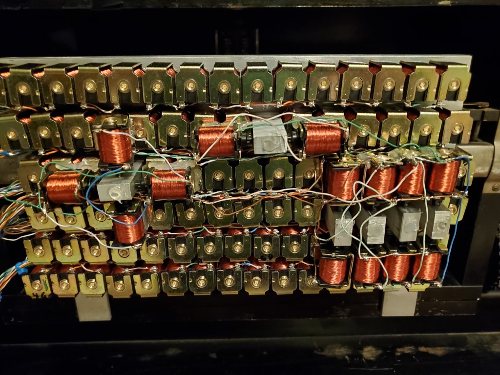
This weekend I had a chance to test the completed valve bank.
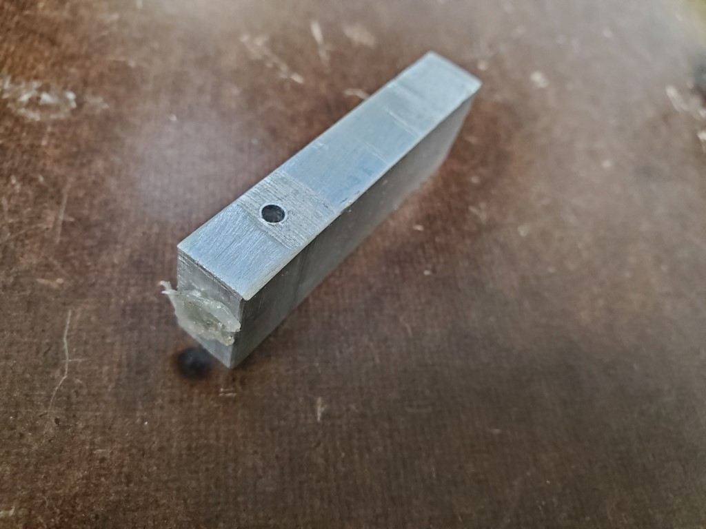
Testing revealed that some of the keys did not actuate with their corresponding valve open. On these keys when the valve (while turned ON/open) was removed from the manifold the key would strike immediately, pointing to lack of airflow through the valve as the cause. I can’t explain why this occurs on only some of the keys but the piano turns 100yrs old next year, so the inconsistency isn’t surprising. The piano could perhaps be adjusted to make these keys work the same as the rest, but I could more easily just provide more airflow via multiple valves per key – this is the approach I took. To connect multiple valves per key I created a few hollow standoffs that fit inside the valve holes in the manifold . The standoffs then have holes on their sides to allow connecting the extra valves on a 2nd layer above the rest. The end of the hole that was drilled to hollow the standoff was sealed with hot glue. Two valves solved the problem for most of the offending keys, but one extra special key required 4(!) valves in a ‘+’ configuration.

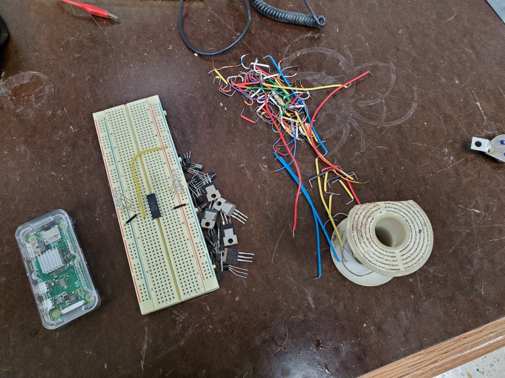
With the mechanical parts complete I’ve taken the first steps to construction of a raspberry-pi based controller that will use shift registers to power the solenoids. The raspberry pi and associated circuitry will be small enough to fit on the back of the valve manifold in the area where the paper roll would normally be. It has wireless connectivity and I plan to have it host a webpage where it can be controlled by phone/tablet. I’m bread boarding this first to prove the concept with one shift register, then once testing is complete I’ll create a circuit board to hold all 11.