

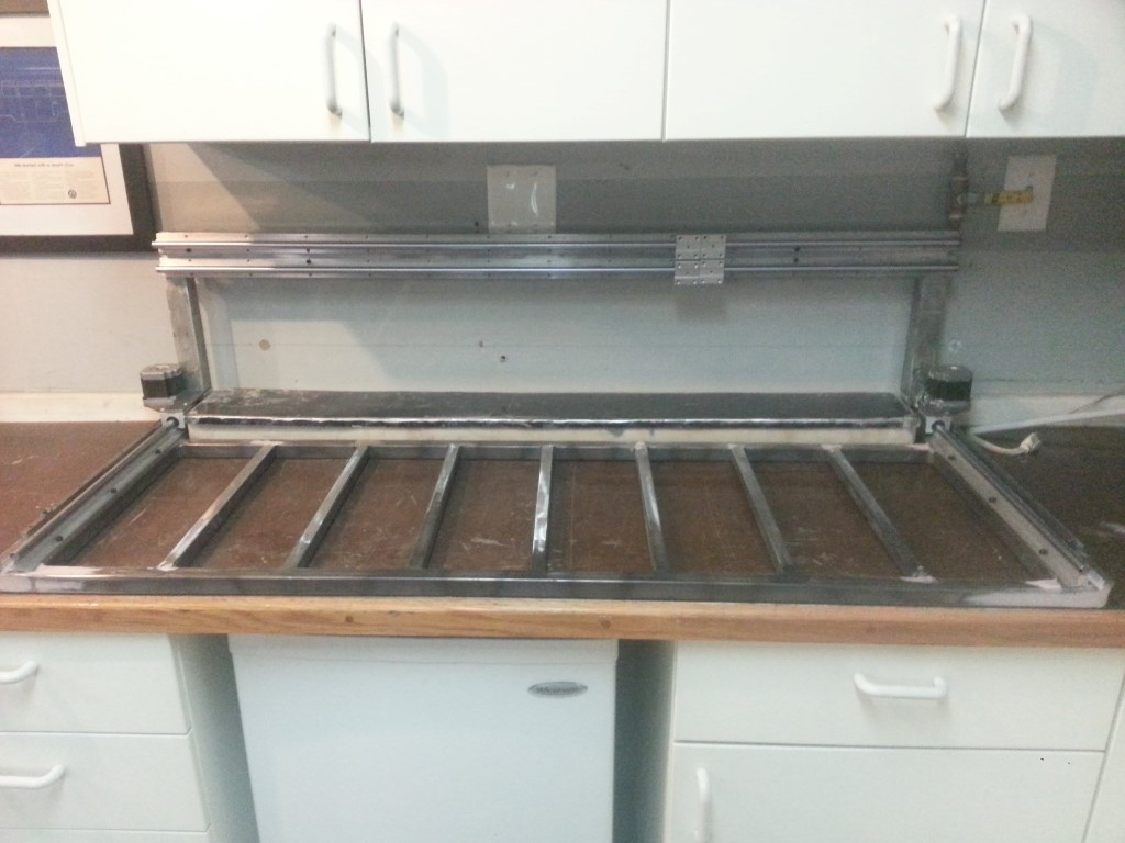
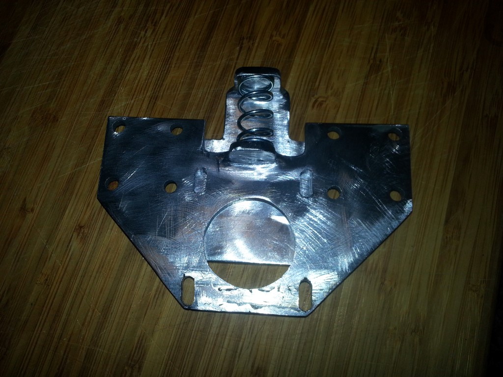
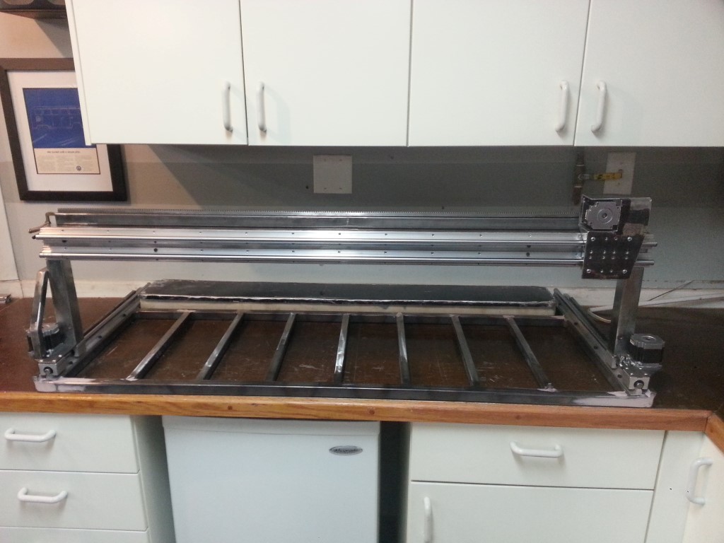
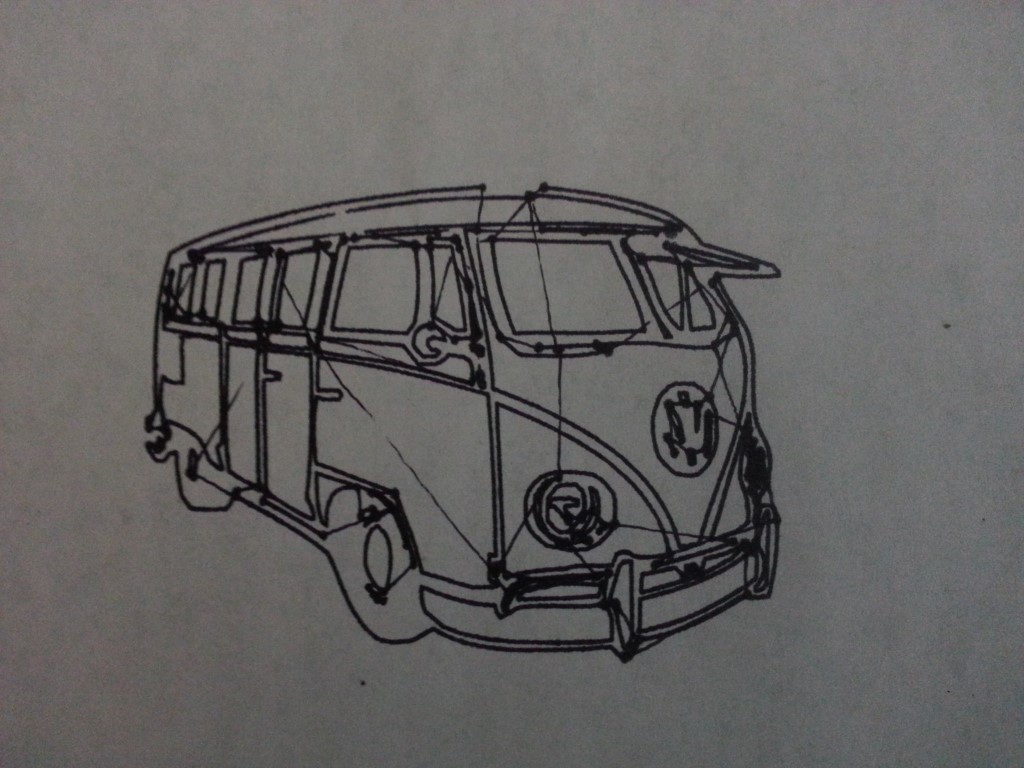
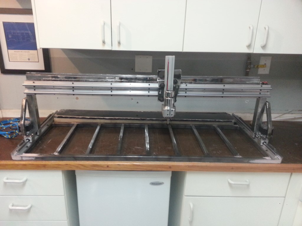
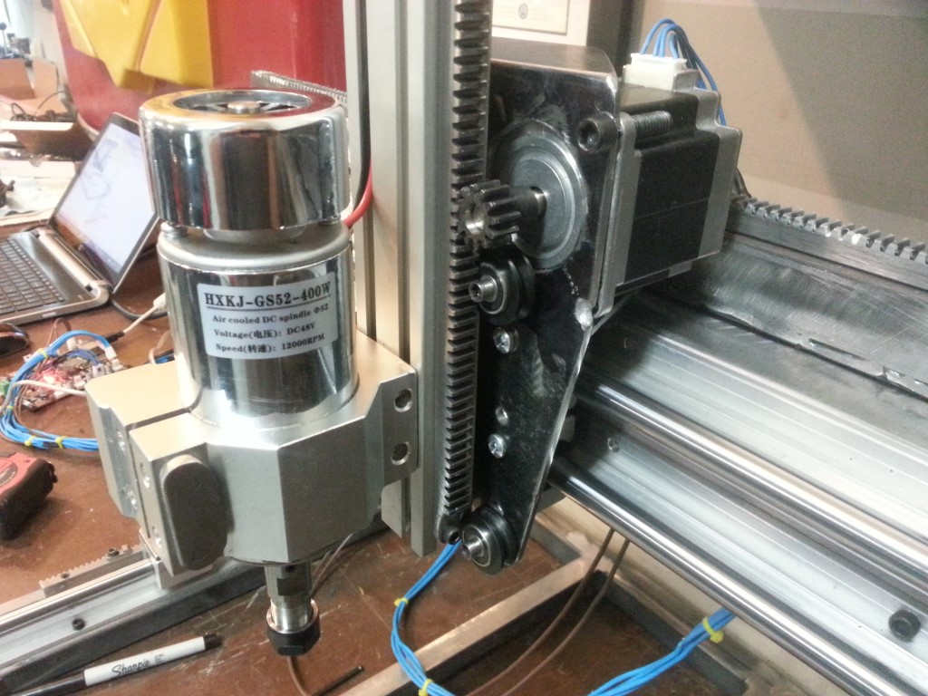
It’s been a while since I’ve updated, and I’ve gotten a lot done during this time. I modified the gantry motor plate (one of them at least) to include a spring tensioner and also added some diagonal braces to the gantry columns; the gantry now runs even smoother and with little or no backlash. I then added the Y axis guides, fabricated the Y axis motor carrier and Y rack support. Once I got all the Y parts together I was able, for the first time, to test coordinated motion between axes by clamping a pen to the Y axis. The results of this testing were great. It drew very accurately with the pen, the drawing path even occasionally required overlapping the same pen line later in the program; it was able to follow the existing lines exactly. The only thing it couldn’t do was lift the pen, since the Z axis wasn’t installed…
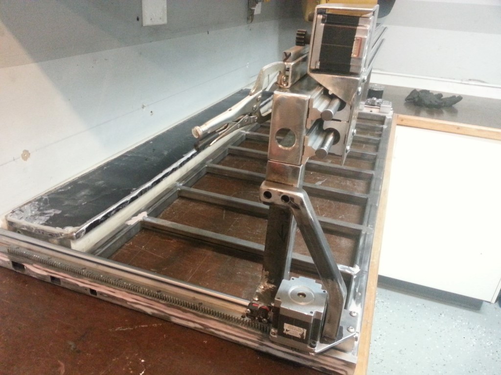


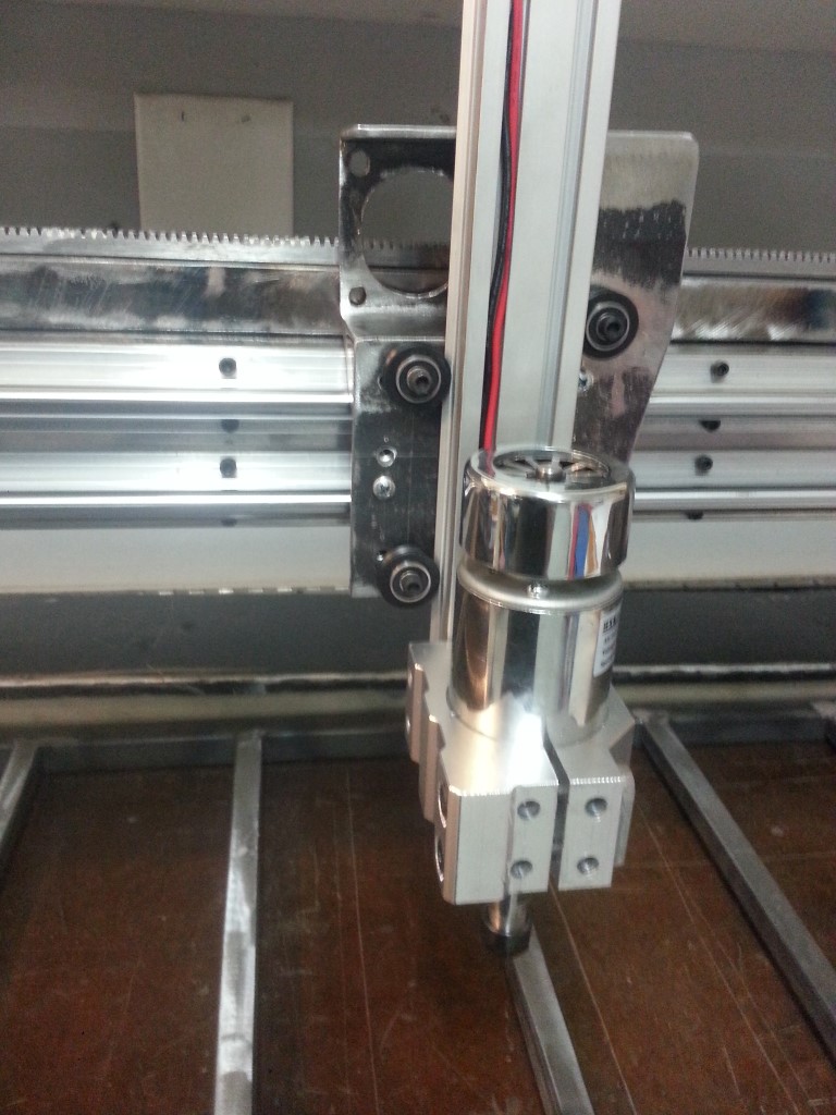
…So after I eventually finished playing with plotting images I began work on the Z axis. The biggest challenge with this was attachment of the spindle mount; the spindle mount is one of the few metal things (other than the motors/guides/racks) that I didn’t fabricate from scratch; despite this I still needed to do some fairly extensive machining/modification to get it attached to the Z extrusion in a very secure but still adjustable way. With the spindle mounted to the Z extrusion the remainder of the work was just some minor drilling, tapping, and cutting. The Z rack is a lot longer than it needs to be for the amount of travel Z has; it was the last rack section to get cut so the extra length is just the leftover/spare, it fits on the extrusion so no sense cutting it off.

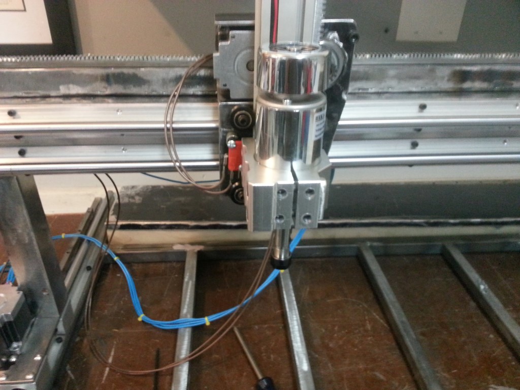
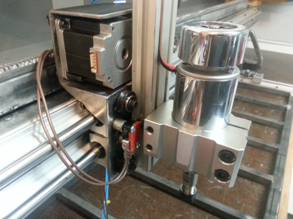
Sometime during initial gantry testing I fried the Z axis motor driver on the smoothieboard when moving the gantry by hand with the drivers off. Z wasn’t even connected during this but my guess is the spinning gantry motors fed back through their drivers onto the supply bus; Z happened to be the weakest and it fried with a snap & flash. Because of this I was actually testing the Z axis with the Y driver. I have an external stepper driver on the way and once it arrives I should be able to move all axes at once and really see what it’s capable of. Next Steps:
#1 – Finish electrical enclosure fabrication
#2 – Modify other gantry motor plate to include spring tensioner
#3 – Final fabrication of cable management, cosmetic covers, etc.
#4 – Disassemble, body work, prime, paint
#5 – Final reassembly & wiring
