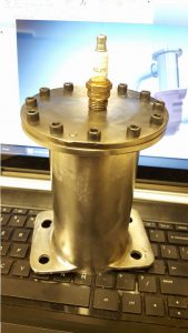
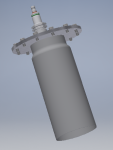
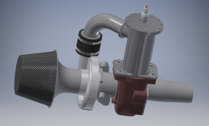
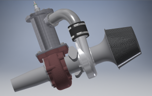
The jet engine combustor is now mostly complete, all that’s left for it is to #1 drill/tap for the spark plug and fuel injector(s) and #2 add an intake duct for compressor air. I’ve also mostly completed the 3D model – there aren’t many straight lines or surfaces on it, remembering all the 3D modeling tricks to make this was a lot of fun. I even went a bit overkill with the model – I may not actually build a bell mouth intake, screen, and/or jet tube.
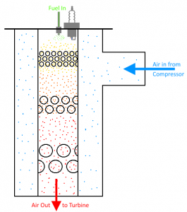
The biggest looming challenge is deciding on a hole pattern for the flame tube. It’s critical that the flame tube holes are in the right places to correctly ‘hold’ the flame through various engine speeds, particularly while starting. If there are too many holes the air will mix too readily and the flame will be blown out, not enough holes and the engine will starve for air and not achieve self-sustaining operation. This is the biggest area for experimentation on the system and it’s why I made the flame tube easily removable from the combustor, modifications may need to be made.
Beyond that, everything else is just basic design, fabrication, plumbing, and wiring:
- Finish 3D module including stand w/ various support systems
- Oil system (Oil tank, oil pump, electric motor)
- Fuel system (This will be propane at first for simplicity and safety, but provisions may be made for future use on Diesel/Kero/JetA)
- Starting system (Air jet strategically aimed at compressor wheel)
- Ignition system (old ignition coil excited by a power transistor pulsed by the control system)
- Electrical design, construction, and programming for instrumentation & control system (tachometer, temperature sensors, etc)


