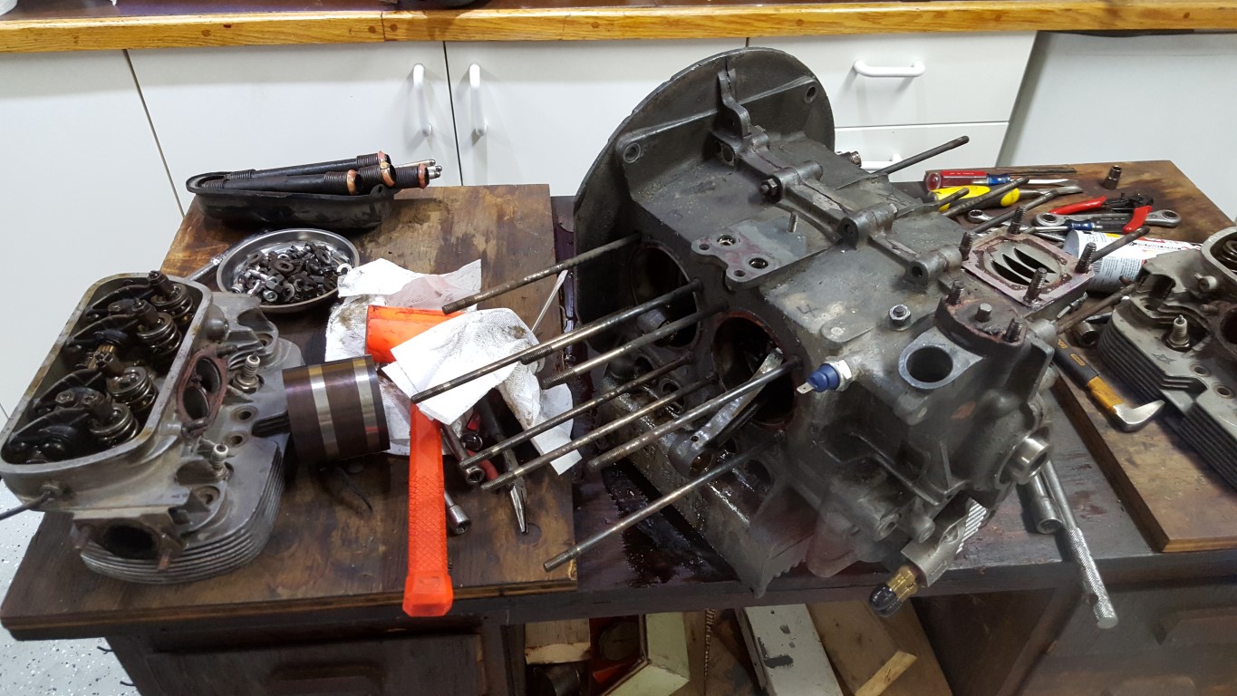
Bus Engine Rebuild
A slight change of direction with the transmission rebuild. I was looking forward to going through the transmission and readjusting everything to make it work again, but to get more speed I would have needed to swap out the ring/pinion gear as well as 4th gear. The cost for these gears separately was not too much different from the cost of a rebuilt transmission that included these gears. Because of this, there’s a rebuilt transmission on the way that already has the ‘correct’ gearing. Since this is a hobby I normally don’t think about time too much, but this also buys me a lot of time that gives me a chance to instead go through the engine while I’m waiting for the transmission to arrive.
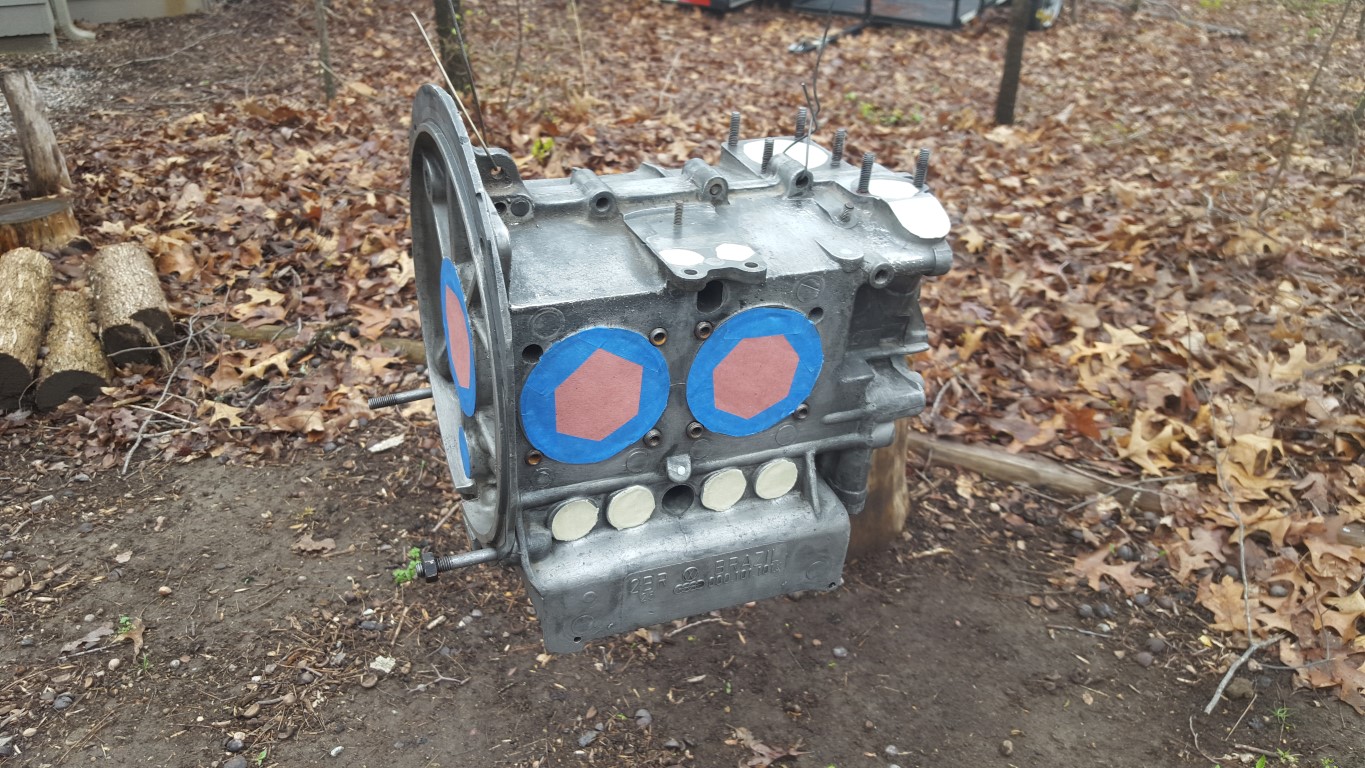
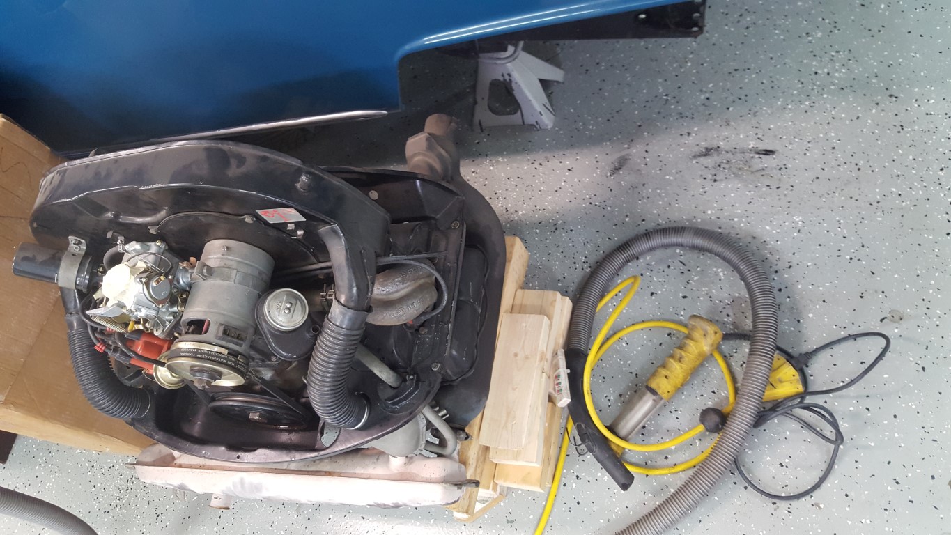
I started going though the engine this weekend. There wasn’t anything necessarily ‘wrong’ with it, but it was put together somewhat hurriedly prior to having the bus at the wedding; I’ve since had a chance to second-guess a few things I did, especially with balance. I stripped it down to the case and this time gave it thin coat of black paint; heat has been an ongoing issue and changing the color to flat black will actually improve heat dissipation slightly. Overall everything looked good, bearing wear looked normal.


VW Bus Transmission – The Sequel
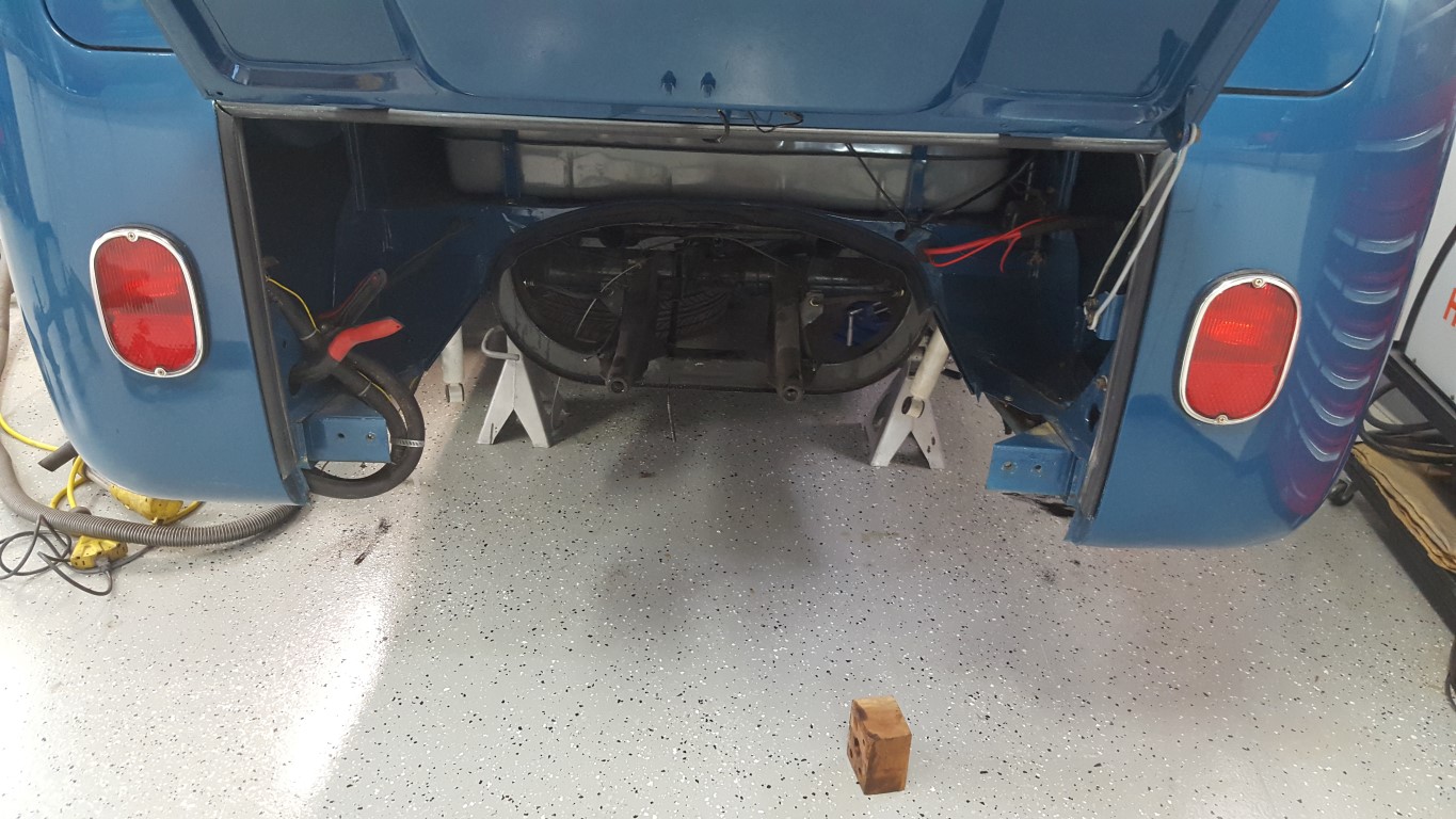
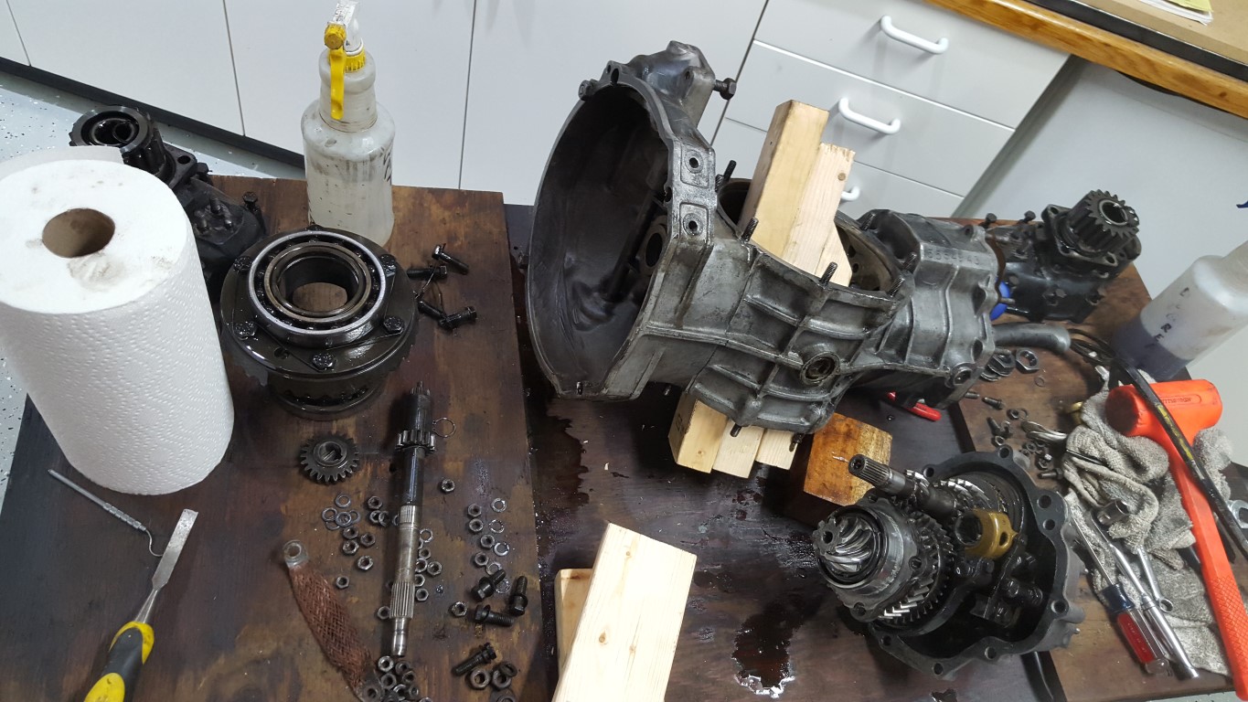
This weekend I finally pulled the engine and transmission from the bus – each time I’ve done this I’m amazed at how few connections there are and how relatively quickly it goes. The goals for this effort are to figure out what happened that caused the breakdown last year as well as fix the problems that had been occurring since the original ‘rebuild’ (more of a clean and reseal). These problems included:
- Immediate pop out of 1st gear and inability to hold in gear. This effectively meant no 1st gear, requiring always starting in 2nd gear.
- 4th gear popped out under load, but could be held in place by a bungee cord. This worked, but is a really inconvenient way to drive and would eventually cause excess wear on the shift forks and slide gears.
- Gear oil leaking from center. This should be an easy fix, I didn’t originally realize the paper gaskets used for the reseal were not treated; using gasket sealer this time should solve this problem.
- Too slow. Currently the bus red-lines in 4th gear somewhere in the low-to-mid 60MPH range, which mostly rules out interstate travel. More flexibility to do longer trips and even to more easily run errands locally would be nice to have. The engine is a little bigger than stock and should be able to handle the higher load, but gearing changes will be needed to get the RPM’s down.
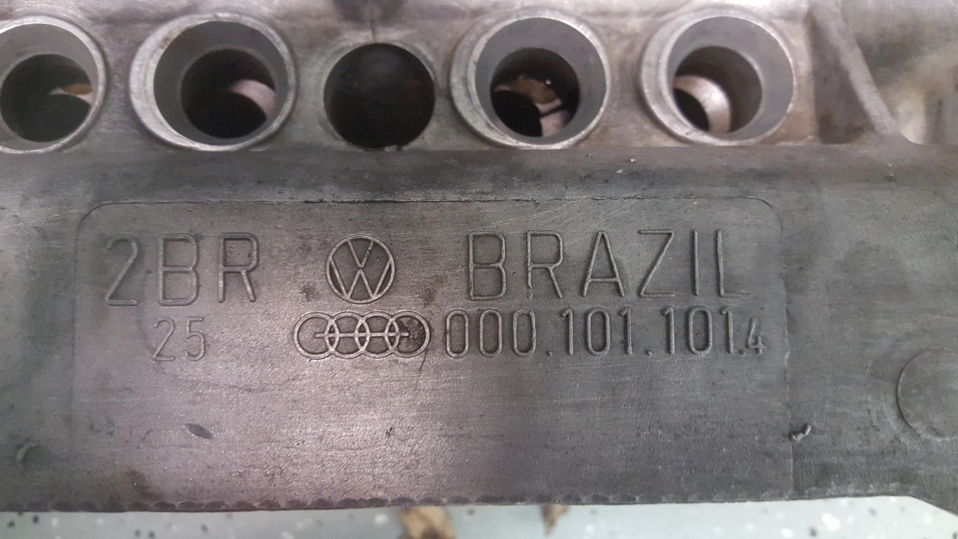
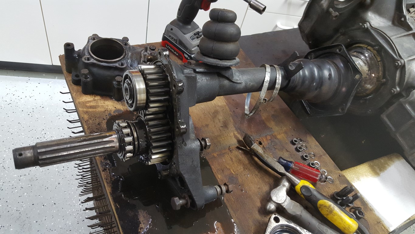
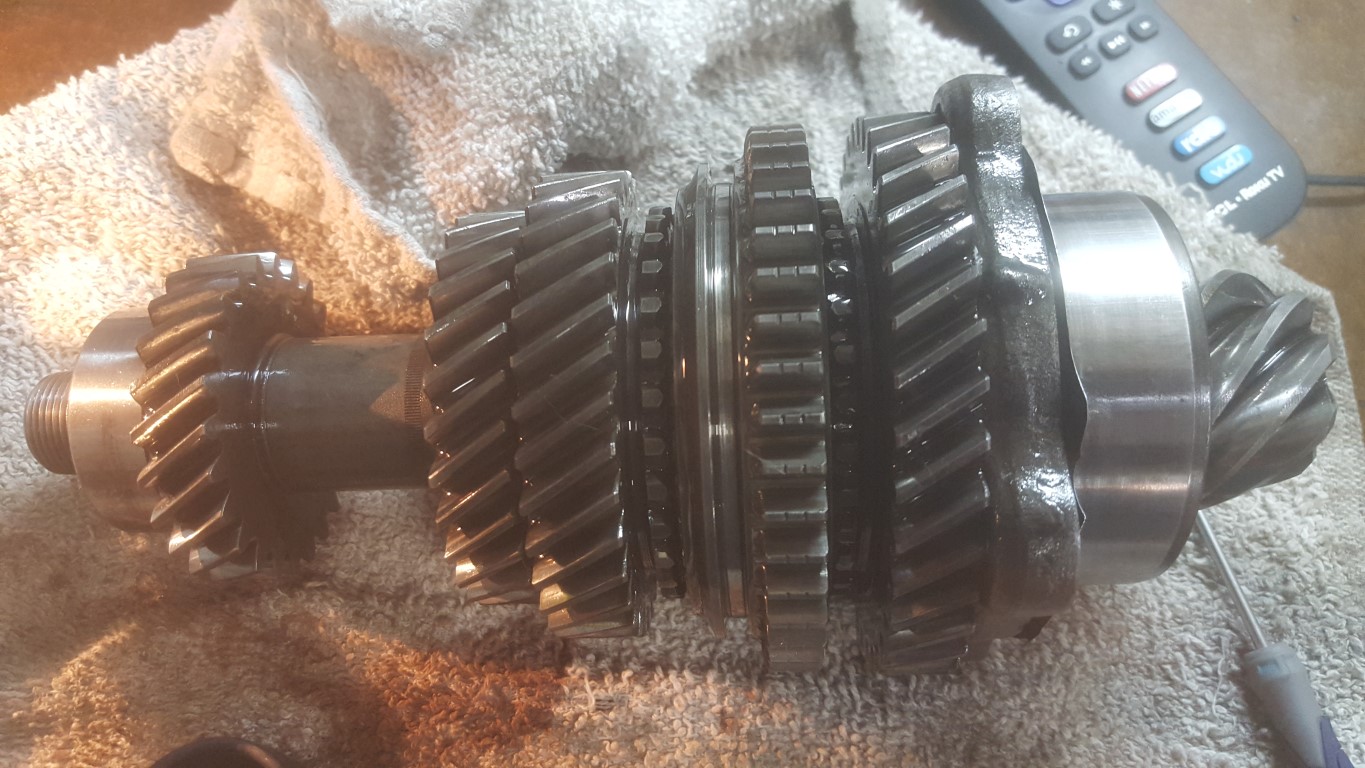
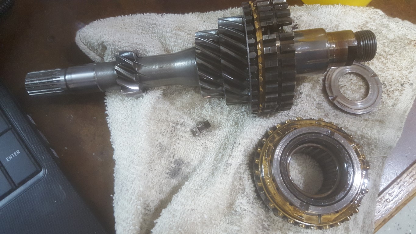
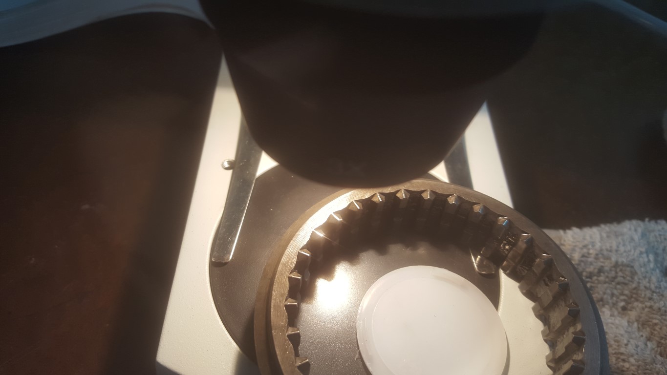
I started disassembly and found that the internals seem to be in incredibly good shape, the teeth show little or no wear even looking under a microscope. All the gear ratios match what would be expected for a ’67 bus except 4th – for some reason it has a 0.88 ratio rather than the 0.82 ratio that would be expected. The 0.88 4th gear would be consistent with a beetle transmission, so I think this information combined with the amazing internal condition tells me that the transmission was replaced with a new or re-manufactured beetle transmission (while keeping the bus axles and reduction boxes) at some point very late in the bus’s history. The top speed would have dropped dramatically after this change and perhaps this contributed to it being parked semi-permanently in the early 80’s.


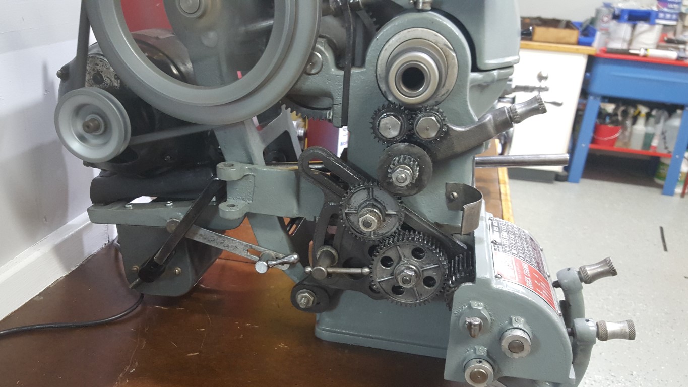
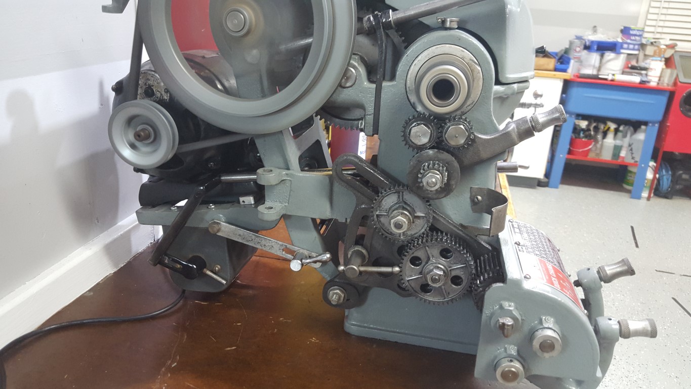
Atlas/Craftsman Lathe Reversing Switch – Finished
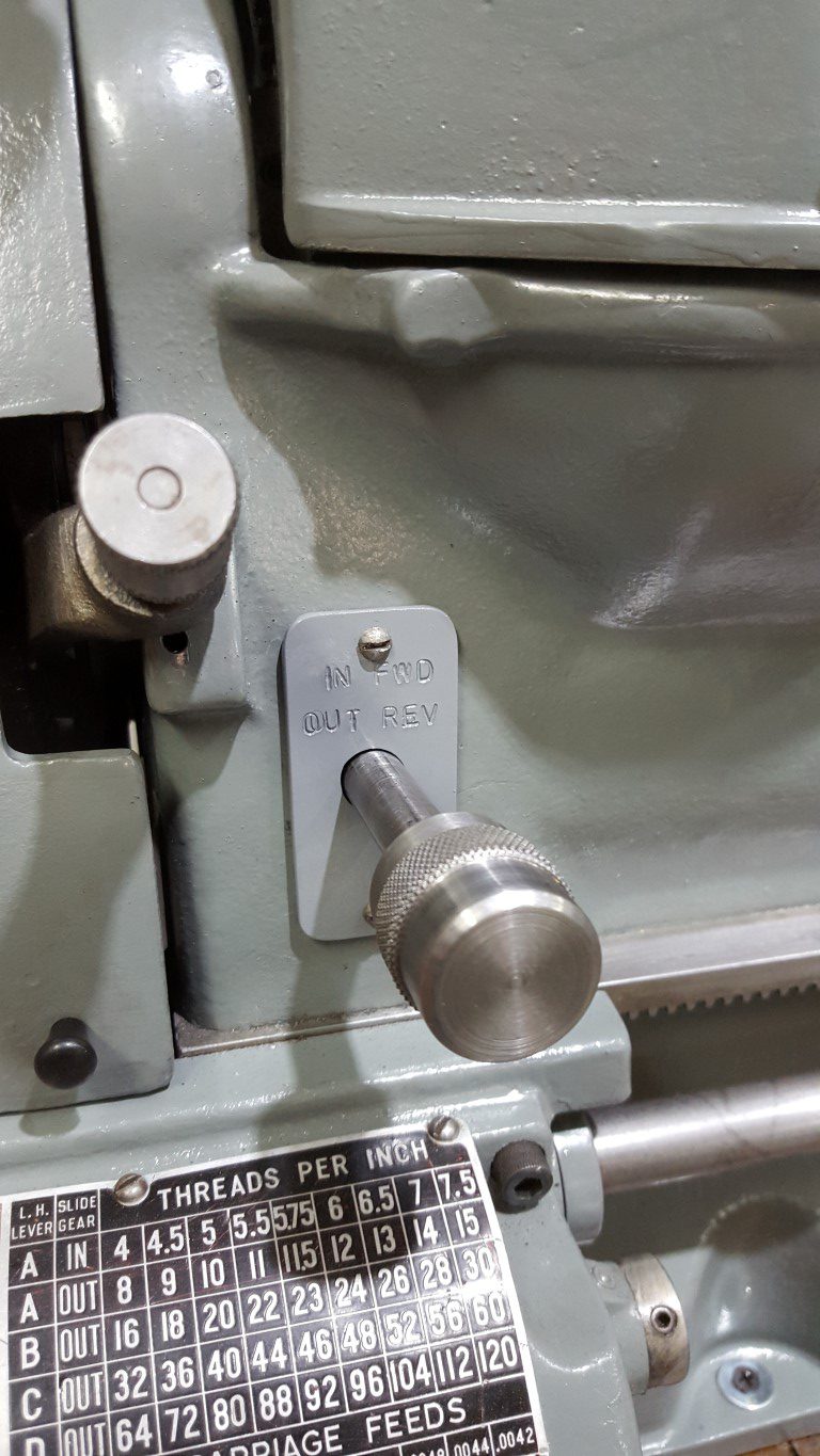
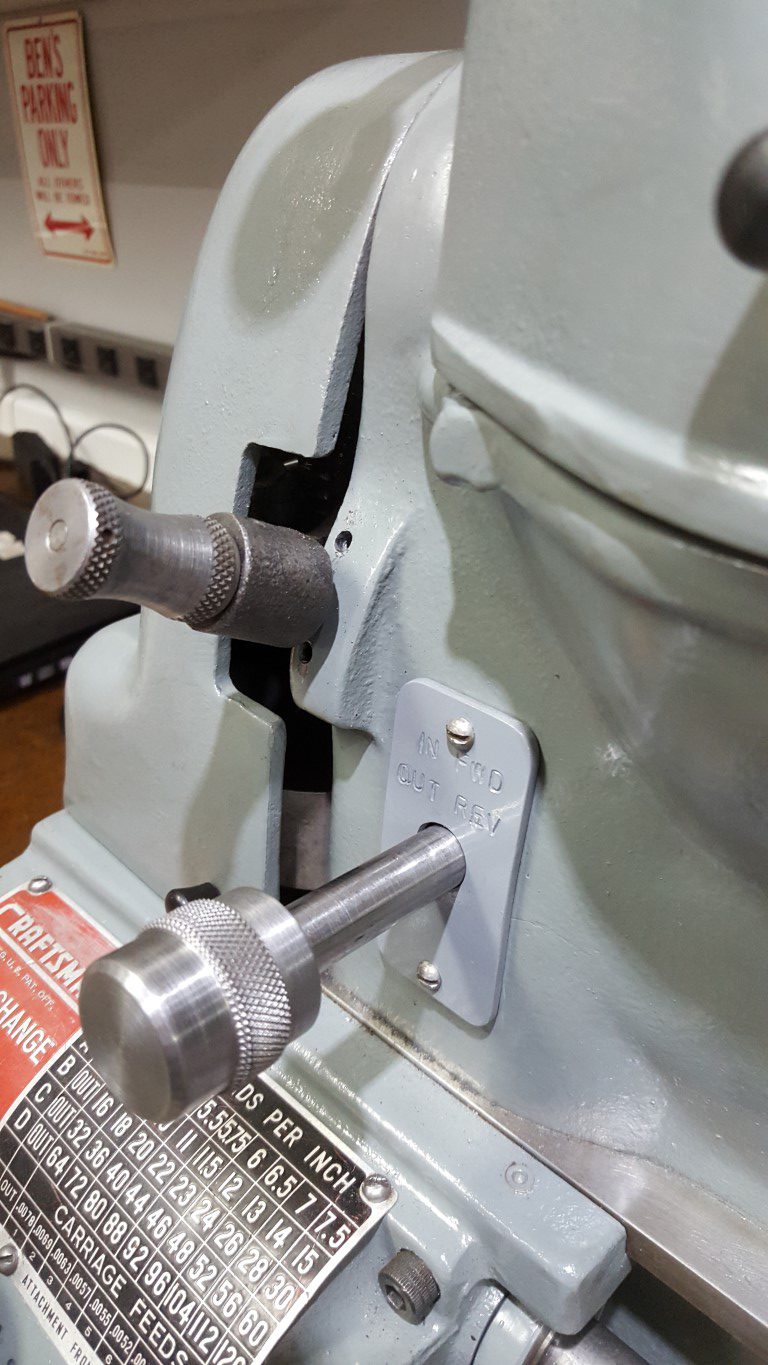
Tonight I finished up the lathe reversing switch linkage by stamping and painting the cover plate and making a knurled knob that roughly matches the others on the lathe. The lathe allowed the inside diameter of the knob to be bored precisely enough to get a good interference fit on the shaft – no need for any fasteners.

Atlas/Craftsman Lathe Reversing Switch
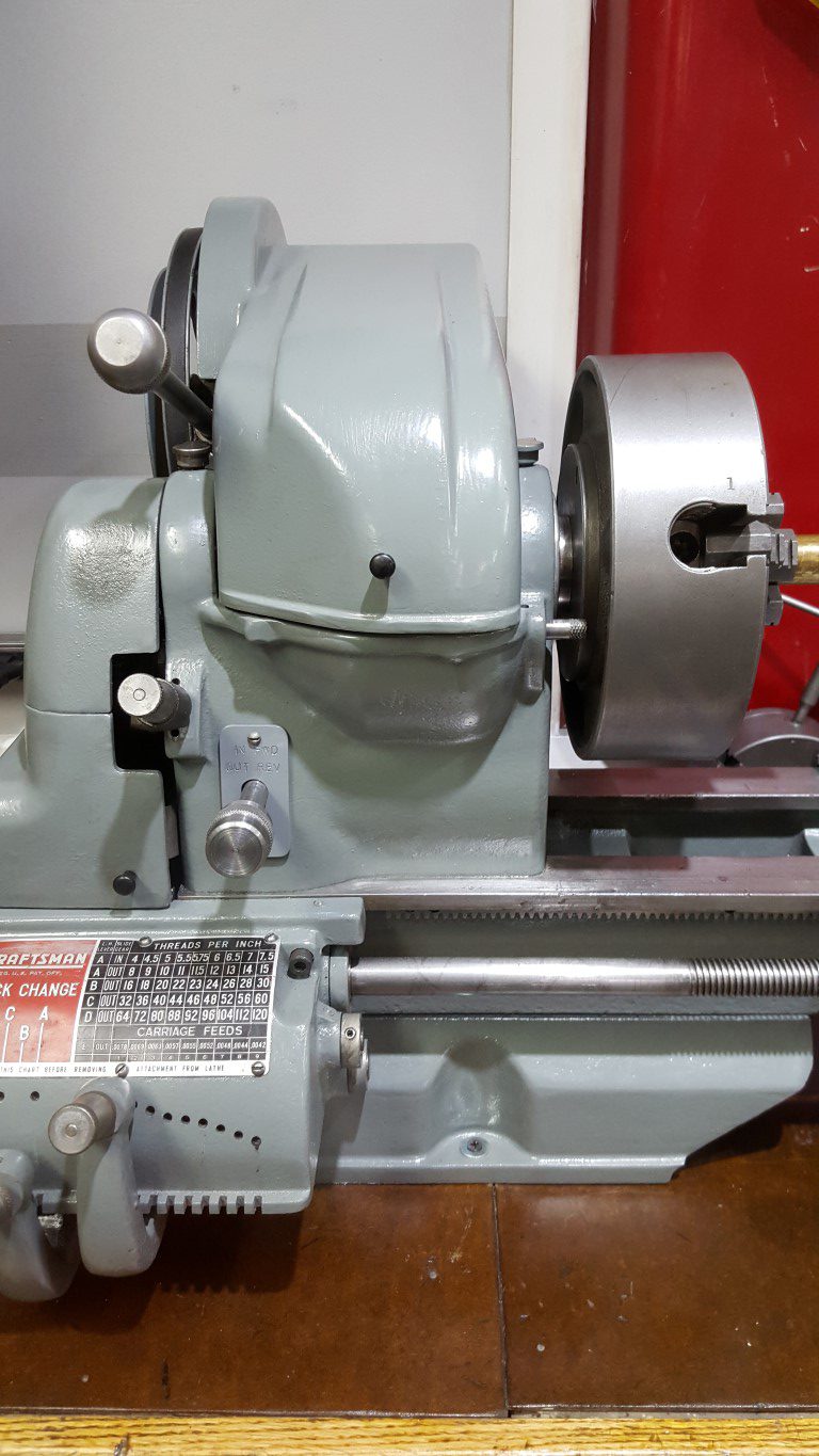
Originally the Atlas/Craftsman lathes spun in only one direction; because of this they came with only an On/Off switch integrated into the lathe’s headstock. At some point in my lathe’s past the On/Off switch was removed and a reversing ‘drum switch’ added. The drum switch gives the flexibility to spin either directions for special uses (cutting metric threads, power tapping, etc) however it’s it’s too big to fit in the lathe’s headstock.
The previous owner had the switch mounted on a wooden arm extending up from the lathe’s workbench; re-using this idea would work but since I’ve moved the lathe to the shop countertop the arm would need to be rebuilt and I also don’t like the aesthetics or the need to reach over the spinning work to turn it on/off. Another option would have been to mount the switch under the lathe base, however for the carriage to clear the switch would require raising the lathe – it was already at a good working height and raising would effect stability/rigidity as well as being susceptible to dripping oil. Lastly, it could have been mounted just anywhere on the ‘outside’ of the lathe (on a guard door, past the tailstock, etc) – none of these locations seemed great and overall this just seemed like giving up.
So what I ended up doing over the past few nights was locating the switch in the only volume of space just big enough for it, under the motor. This location has the added benefit of making the wiring short and simple. As-is, this is of course very inconvenient, but I chose it with creating a linkage in mind. The addition of the linkage allows the original On/Off switch hole to be utilized (previously this was just an open hole), puts the control in a convenient place, and makes it look like it was designed this way. The linkage was a challenge and took a few iterations to get right. It consists of a 1/2″ OD steel tube that runs through the headstock, supported by two metal plates I fabricated. At the end of the tube I welded on a nut to accept a bolt that bolts on another arm I fabricated. The arm has a bolt welded through it that engages with a slotted lever welded to the drum switch’s lever. The resulting contraption actually works very smoothly: pushing IN runs the spindle forward, pulling OUT runs it reverse, and returning to center is Off. All that’s left to do is create a matching knob and mark/paint the switch plate.