

Stepper Motor Testing
The racks, pinions, and power supply arrived yesterday and I setup a trial run to verify the motors would have enough speed/torque with the selected gear ratio. First, I bored a few thousands out of the pinions to allow a press-fit onto the stepper shafts. Next I pressed the pinions onto the stepper shafts; luckily the steppers have a hole in the back of the case that allowed me to support the other end of the motor shaft so that no force went through the motor bearings. I then verified the pinion/shaft run-out with a dial indicator; all except one were well under a thousandth. I was able to bend the one with a few thousandths run-out to match the rest; there was no way to protect the motor bearings during this process though so hopefully I didn’t cause any longevity problems.
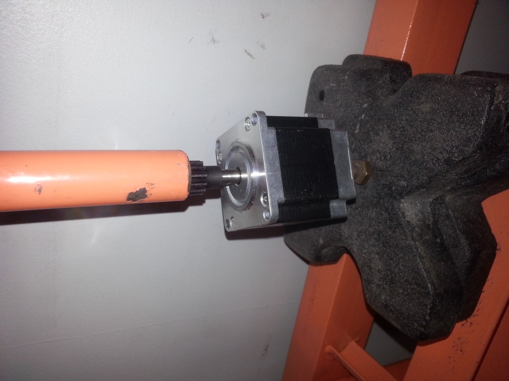
Once all the pinions were in place I cut the racks to final length and modified the Smoothieboard electronics and configuration files to accommodate a 2nd (and inverse rotation) motor on the X axis. I then wired it all up and began testing. It all seems to work great and I was getting what seems to be plenty to torque all the way up to 1200in/min. The rack also seemed to have very little backlash, even over a range of different engagement depths. I don’t have any good way to measure the torque, so I just pushed against the rack by hand with a force that I assume is far greater than the moving/cutting resistance. So it remains to be seen if 1200in/min will be the actual speed; I also verified there is even more torque at lower speed, so I can always slow it down if need-be. Speed will probably be limited more by the spindle/tooling/material anyways.
CNC Machine Planning Pt2
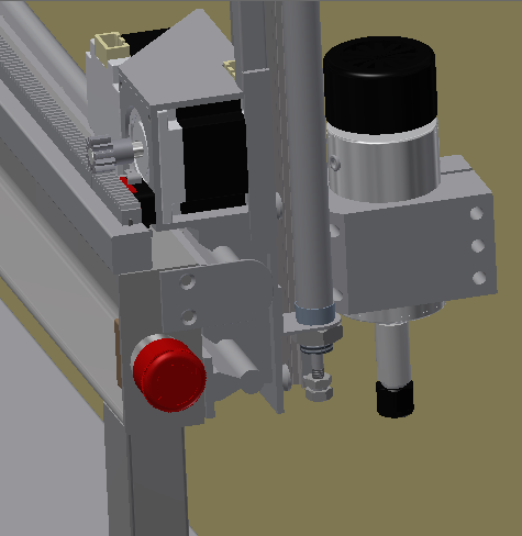
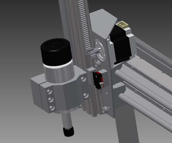
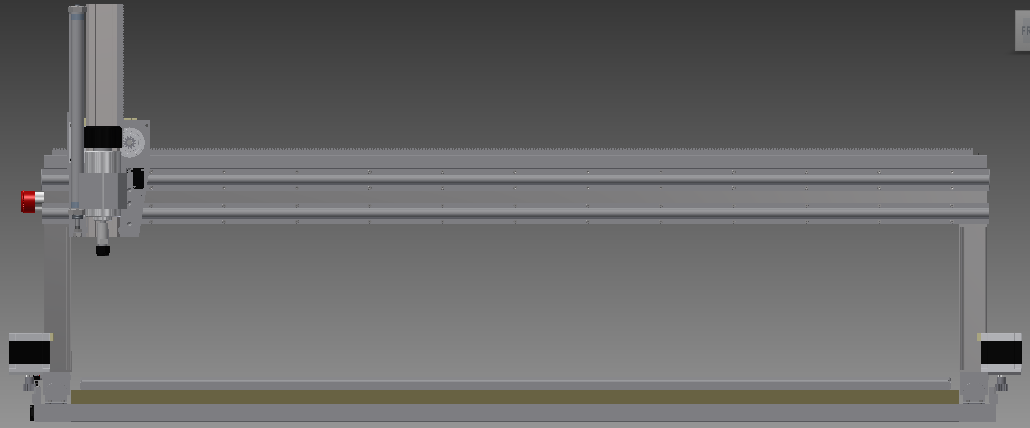
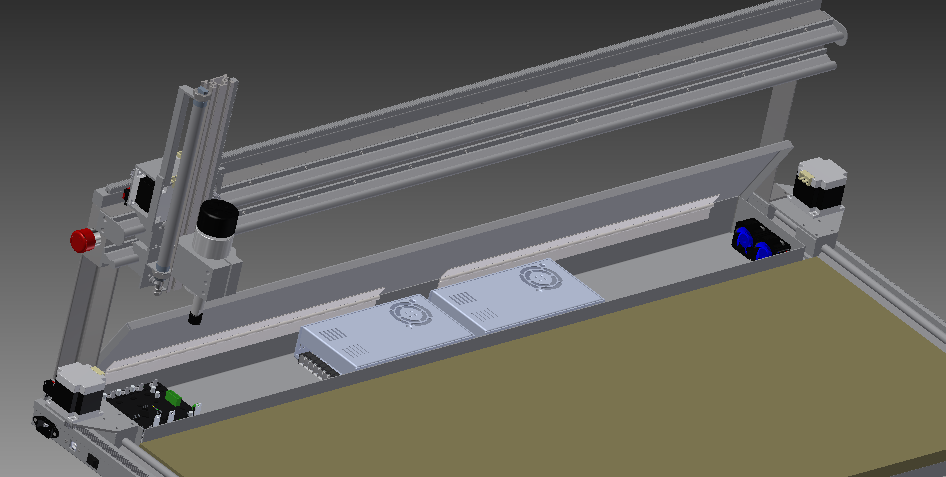
Since the last update I’ve completed the machine design and ordered a majority of the metal and mechanical parts. Some of the components’ 3D models (smoothieboard, power supply) were available online, which saved some time, but I had to model the majority from scratch. The design uses all the actual part dimensions to ensure there won’t be any part interference and that the range-of-motion will be OK. Getting the dimensions right so that there is no interference while also not having any wasted travel is actually much harder than it looks and a lot of time was spent perfecting this. As a result, the clearances are fairly tight, but this machine is meant to be as compact as possible so this is intentional. The overall usable table size worked out to be 48″x18″, with a machine footprint of 52″x24″. Some design highlights:
- Strategically placed bolted connections to allow for adjustment of squareness and rack/pinion mesh.
- Minimize weldment complexity and dimension criticality. It will still require a lot of attention during fabrication, easily the most dimension-critical thing I’ve fabricated.
- X rails flush with the back of the table to allow for future expansion.
- Parts will be held to the table with temporary clips screwed into a sacrificial fiberboard table;when the fiberboard becomes too full of screw holes it will be replaceable. The spindle centerline will be able to reach every part of the table to allow it to be surfaced flat.
- The electrical enclosure occupies the rear area that is unreachable by the spindle. Unfortunately the height of the power supplies makes the enclosure higher than the table surface, so if the machine needs to be temporarily expanded I’ll have to build up the table surface over the enclosure and sacrifice some Z travel. This won’t be a big problem though since the type of things I’d do in ‘expanded table mode’ wouldn’t require much Z anyways. (Making the base taller would have fixed this, but since it’s going to live on the workbench all the time I’d rather keep the base as flat as possible)
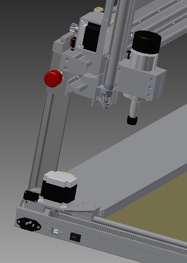
- Z axis uses a standard extrusion; this will give the most flexibility with mounting different tools
- I included a provision for a pneumatic cylinder in the design to counter-balance the Z axis. This will allow the Z axis weight to be precisely offset by adjusting air pressure. I’ll wait and see how it works though before deciding to either add this, a gas strut of the same size, or nothing.

CNC Machine Planning
I’ve had on my list for a long while now that when the bus was ‘done’ I’d get back into hobby electronics/robotics. I can’t think of a better way to kick this off than by creating a CNC machine; it’s a fun project on it’s own but will also make many of the miscellaneous fabrication tasks for projects of all categories (hobby/bus/home) easier, faster, and of much higher quality.
Design Requirements:
#1 – More or less fit within a 4ft wide by 2ft deep x 20in tall area; allowing it to live full-time on the garage workbench without being in the way. Also attempt to minimize deck height and park moving axes flat against the back wall for the same reason.
#2 – Be able to cut 4×8 material if needed. (Does not conflict with #1, design just needs to allow for future temporary extension & relocation)
#3 – Initial build will be a router, but the design needs to be flexible enough to support future tool types (3D printer extruder, drag knife, low power laser, etc)
#4 – Accurate enough for #3; maybe +/- 10 thou?
#5 – Rigid enough for #’s 3 & 4, but not to the extent that it becomes an immovable object like a Bridgeport.
#6 – Faster than a snails pace but speed isn’t all that important, not a production line machine.
#7 – Reduce cost to the lowest possible while maintaining good quality. Utilize all welding/machining/painting skills learned in other projects to build mostly from raw materials to save cost. Utilize “off-the-shelf” components in creative ways.
As far as machine configuration goes, the choices are: Delta, Cartesian, or SCARA. I made a quick sketch of the simplest forms of each below. Although the delta configuration is currently very popular in the 3D printing world, I immediately ruled it out as being incompatible with my size and tooling requirements. A SCARA configuration was very tempting as it could fold itself up into one corner when not in use. I had to rule it out though because the geometry is just too weird for my liking, all limits and resolution are polar; in other words the resolution changes with distance away from the base and the machine limits are circular instead of rectangular. This left me with the tried-and-true Cartesian configuration.

I’ll base the controls on the open source SmoothieBoard project, which itself is based on the open source GRBL (pronounced ‘Gerbil’) project. I’m confident I could have designed/built/programmed this all myself from scratch and it would have worked, but wouldn’t be quite as good as a well developed community-based project and I’d rather just focus on getting the overall project up and running. The SmoothieBoard will directly drive at least three 2A stepper motors (X/Y/Z), and perhaps also a 4th motor working in parallel with one of the others depending on the mechanical design.
I’m dusting off my old student copy of Autodesk Inventor and beginning on the mechanical design now. It’s still very much in the initial stages and I’d rather build it digitally 20x and physically once, so it may take a while to perfect to the point of beginning construction. Currently some of the brainstorming questions are:
Machine frame?
Black Pipe: +Cheapest Option, +Cast Iron good at damping, -Bad Tolerances, -Weldability Questionable
Mild Steel Tubing: -/+ Good middle ground between other two options?
Aluminum Extrusion: +Quick assembly, +Good Tolerances, -Expensive, -“too easy”/looks-like-an-erector-set
Drivetrain?
Rack & Pinion: +McMaster has decent looking sets for reasonable cost, +Easy to extend, -Backlash
Ballscrew: +Low Backlash, -Even the ‘cheap’ ones are expensive, -Impossible to extend temporarily
Belt or Chain: +Simple to experiment with ratios, -Difficult to extend temporarily, -Stretch/Backlash
Linear Guides?
Homemade: +Design Flexibility, -Requires complex fabrication of slides w/ small bearings
Bought: +Known-good performance, -Expensive, -Limited length/size options
Is there a 3rd option? Possible to buy slides to use with some nominal tubing size?
Winter Update
Aviation: Winter is here and with it has come lots of overcast weather that’s no good for flight training, slowing progress quite a bit. In total I’ve now soloed 6-8 times and have started working on cross-country training. Cross-country flying adds many new elements: flight planning, talking to Air Traffic Control, radio navigation, visual navigation by waypoints, etc. All this has to be done while still flying the plane, so it’s definitely a challenge. Currently targeting to have my FAA checkride sometime before April.
Bus: Winter also puts a damper on bus driving since I don’t have the heat connected yet. On the last drive before the temperature dropped I had a big loss in power every few minutes and had to pull over and idle before power came back. I haven’t looked into it yet but this seems consistent with a clogged fuel filter; I was expecting the first filter to go quickly since it’s filtering out all the rust/varnish/trash from the fuel tank that sat for 30 years. I probably could swap the filter and have it going again but I think this is a good opportunity to now pull the engine/trans again and go through it with a fine-tooth comb with the goal of getting it smoother/quieter/stronger to enable longer trips. No immediate plans to do this, probably when the weather warms up.
Tech Projects: I just ordered a float valve to automate refilling the Keurig, I’ll post pictures of how that goes. Also I’m getting interested in making a small CNC machine; I’ve had this on my long-term to do list for a while but recently component prices have dropped substantially so I’ve started the planning process.
