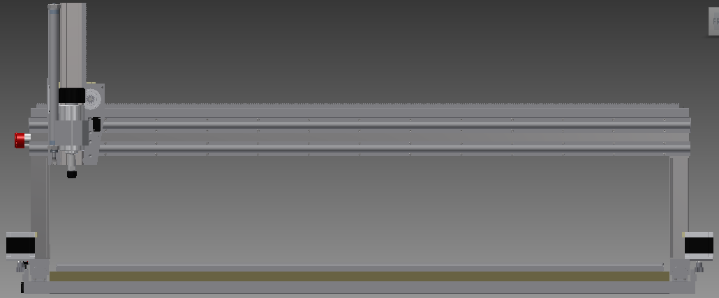
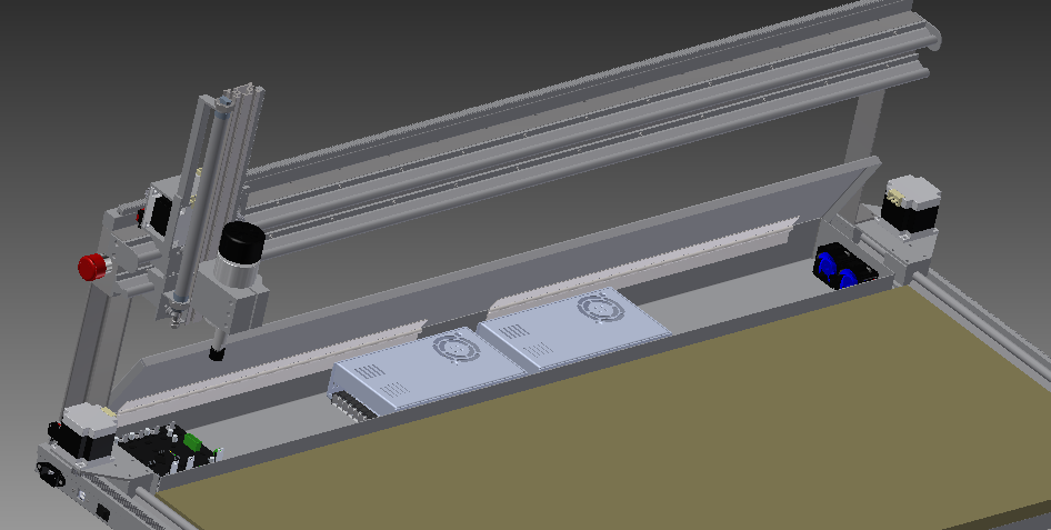
Since the last update I’ve completed the machine design and ordered a majority of the metal and mechanical parts. Some of the components’ 3D models (smoothieboard, power supply) were available online, which saved some time, but I had to model the majority from scratch. The design uses all the actual part dimensions to ensure there won’t be any part interference and that the range-of-motion will be OK. Getting the dimensions right so that there is no interference while also not having any wasted travel is actually much harder than it looks and a lot of time was spent perfecting this. As a result, the clearances are fairly tight, but this machine is meant to be as compact as possible so this is intentional. The overall usable table size worked out to be 48″x18″, with a machine footprint of 52″x24″. Some design highlights:
- Strategically placed bolted connections to allow for adjustment of squareness and rack/pinion mesh.
- Minimize weldment complexity and dimension criticality. It will still require a lot of attention during fabrication, easily the most dimension-critical thing I’ve fabricated.
- X rails flush with the back of the table to allow for future expansion.
- Parts will be held to the table with temporary clips screwed into a sacrificial fiberboard table;when the fiberboard becomes too full of screw holes it will be replaceable. The spindle centerline will be able to reach every part of the table to allow it to be surfaced flat.
- The electrical enclosure occupies the rear area that is unreachable by the spindle. Unfortunately the height of the power supplies makes the enclosure higher than the table surface, so if the machine needs to be temporarily expanded I’ll have to build up the table surface over the enclosure and sacrifice some Z travel. This won’t be a big problem though since the type of things I’d do in ‘expanded table mode’ wouldn’t require much Z anyways. (Making the base taller would have fixed this, but since it’s going to live on the workbench all the time I’d rather keep the base as flat as possible)
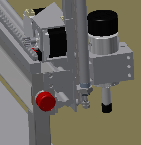
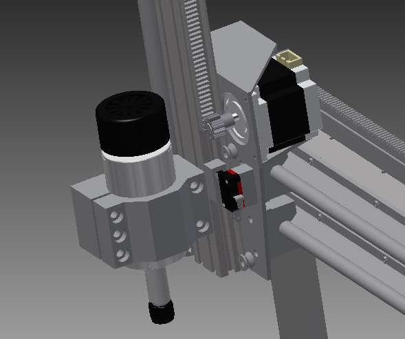
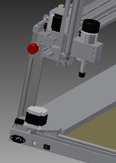
- Z axis uses a standard extrusion; this will give the most flexibility with mounting different tools
- I included a provision for a pneumatic cylinder in the design to counter-balance the Z axis. This will allow the Z axis weight to be precisely offset by adjusting air pressure. I’ll wait and see how it works though before deciding to either add this, a gas strut of the same size, or nothing.