E-Ink Bank Calendar
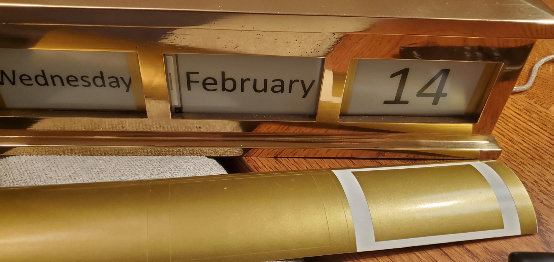
I was recently given a brass calendar frame that normally holds a collection of small cards corresponding to the date. The top lifts off and the cards are re-arranged to display the day’s date. I decided to automate it with the following:
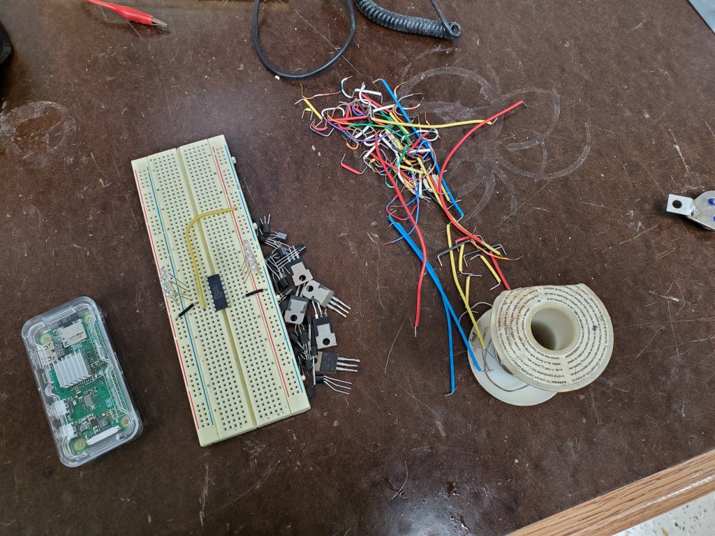
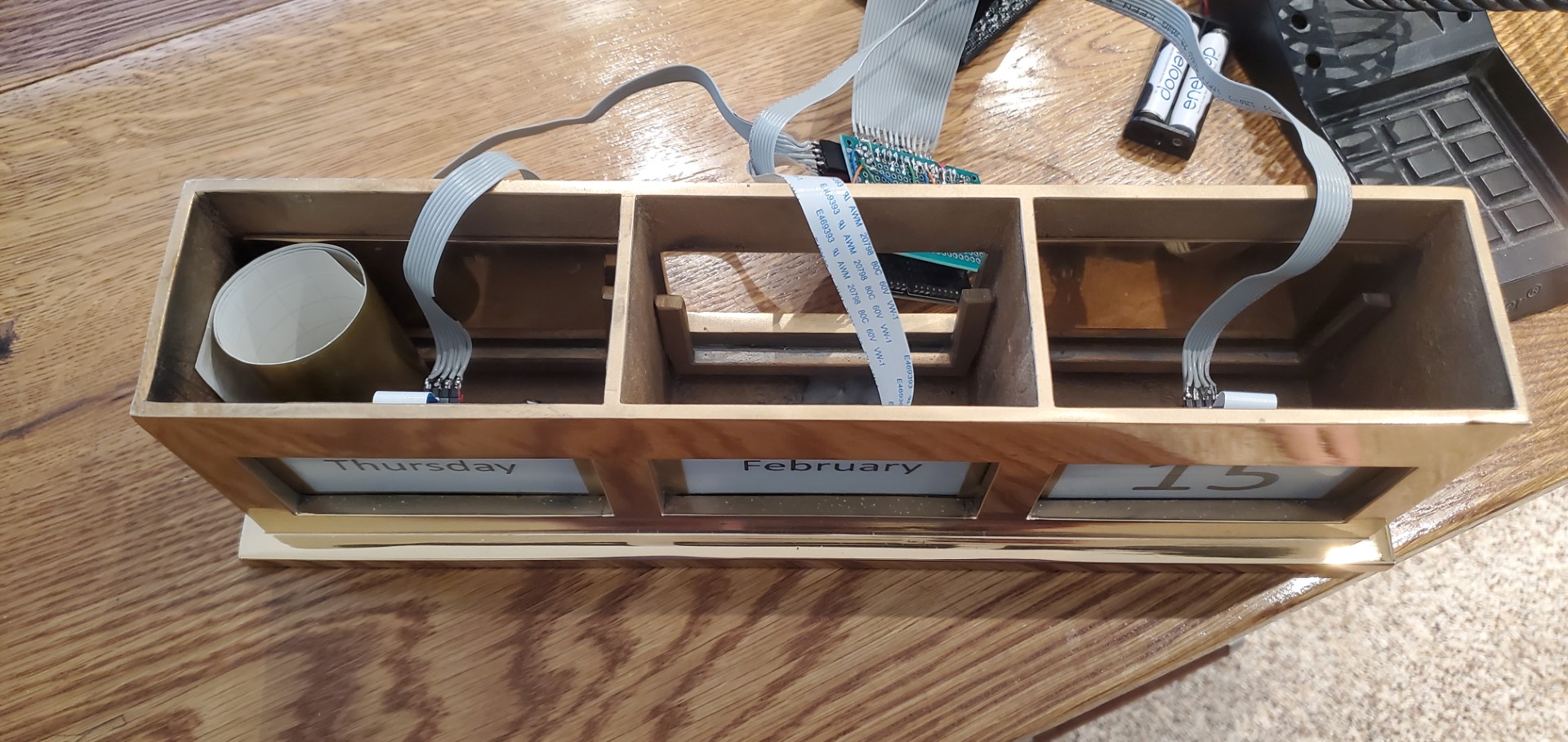
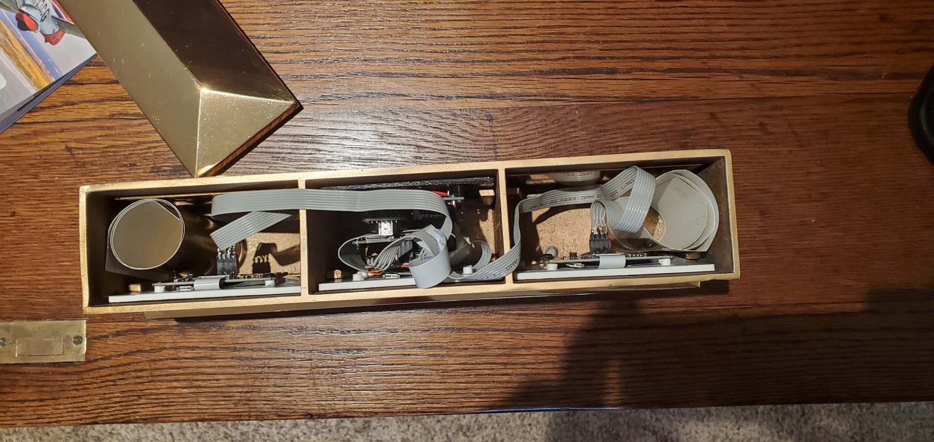
- Arduino Pro Mini, ATmega328P microcontroller board (1x) Main controller for the system, runs the code integrates everything else.
- DS3231 Realtime Clock module (1x). This keeps track of the time/date. It has its own small battery to stay running while main system power is off.
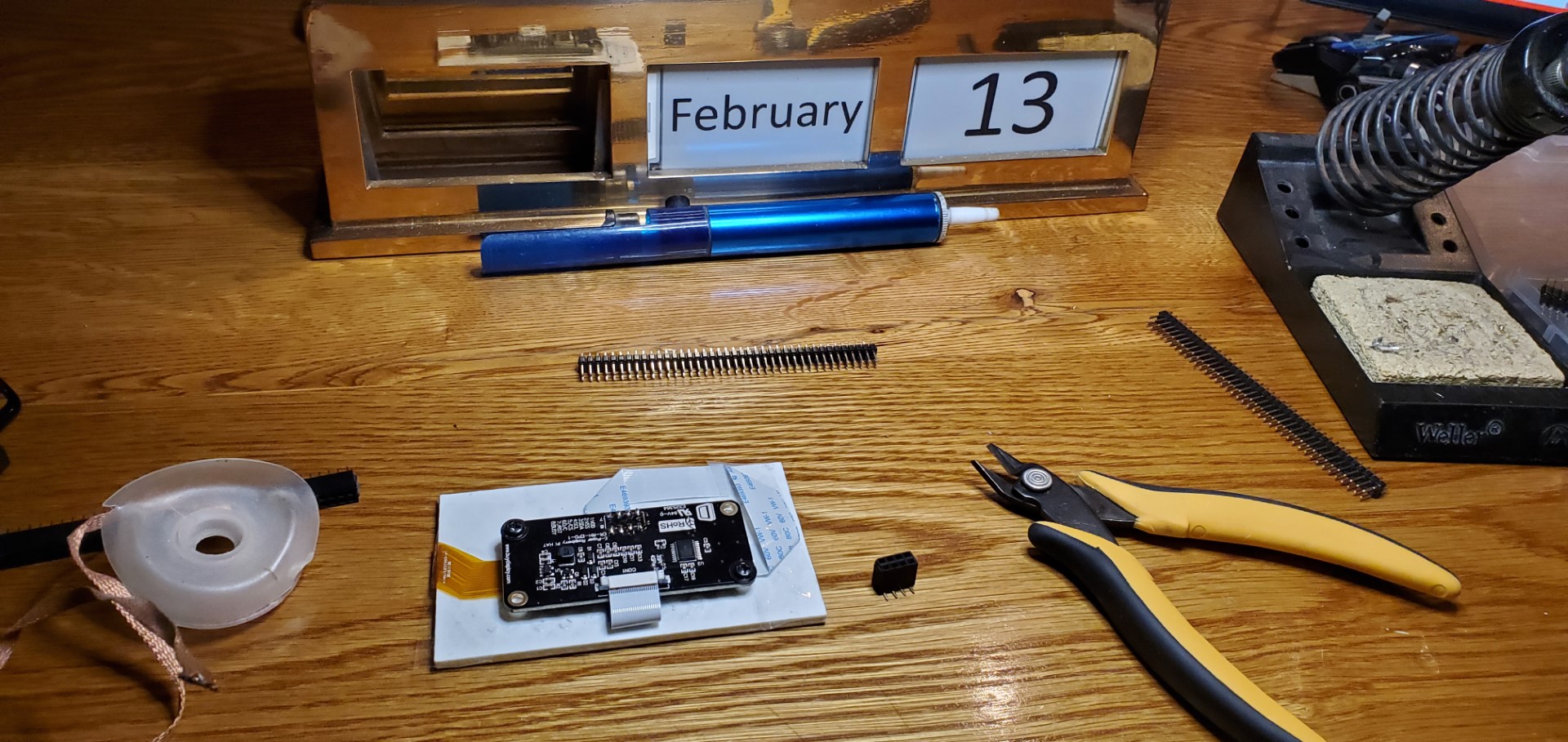
- 3.7″ Epaper displays(3x).
- Epaper connector board (2x) – mainly just a breakout board for the epaper display’s ribbon cable, but it also handles signal buffering and making a few weird voltages that the epaper display needs.
- Epaper interface board (1x) – same as the connector board, but also has onboard SPI RAM and MicroSD card slot.
I’ve designed many various electronic circuits/devices, but this is the first I can recall where the power budget matters a lot. The power usage would always be low with these devices, but I wanted to avoid a scenario where it’d need a wall wart plug – the goal is for it to run a reasonably long time, a year or so, on a rechargeable battery. The magic of the e-paper displays (other than having the image very close to the surface, looking more like real paper than a display) is that they can be completely powered off and still retain their image; that’s a huge head-start to low power usage. This left the micro-controller as the main risk for power consumption, however with careful use of interrupts I think I’ve optimized this. The sequence, which happens every night at midnight, is:
- DS3231 asserts its alarm pin
- The alarm pin is connected to an interrupt on the ATmega328P which has been configured to wake the microcontroller and begin code execution.
- The microcontroller communicates with the DS3231 over I2C to read the new date and resets the alarm for the next midnight.
- The microcontroller reads the SD card to lookup graphics corresponding the 1st display based on date, this is read into RAM and then shifted to the epaper display. This repeats for each display. (The controller inside each display goes through its own routine for the physical screen update that causes the screens to flash Black/white several times)
- The microcontroller goes back to sleep mode, no code execution and extremely low (almost no) power usage until next midnight.
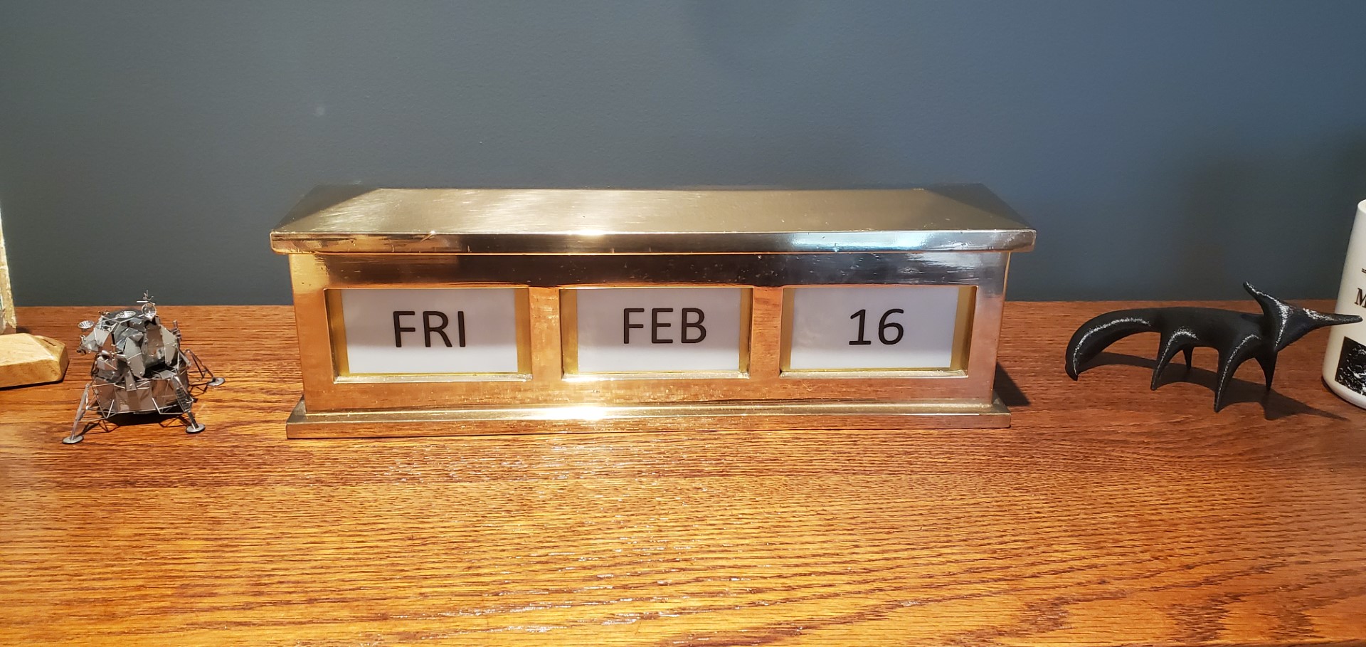
With this sequence it’s very nearly off the vast majority of the time, only the small clock battery on the DS3231 module keeps it going; then everything else only wakes up for a few seconds at midnight to update the screens. Time will tell how efficient this is, but it should be as good as theoretically possible. The DS3231 battery is meant to hold the time for ~10yrs, when the main battery is depleted the screens will stop updating but time won’t be lost – proper date will be displayed on the first update after a recharge without any need to set the time/date.
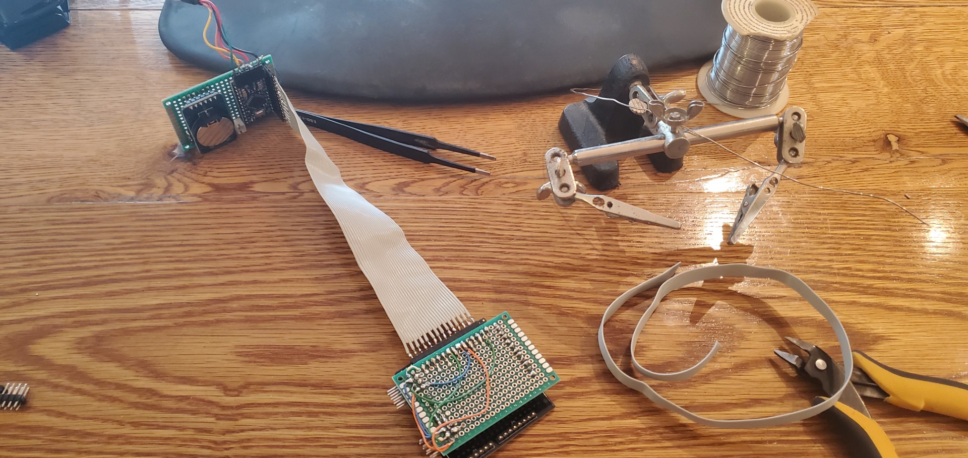
The software for writing to the epaper displays leans heavily on the example provided with the displays, but the example assumed only a single display. Since I had limited IO pins and there was no need to update displays simultaneously I modified the library to accept a display index for each function. With this, I was able to put everything on the same SPI bus and share the SD/RAM between all displays, the library just only asserts the chip select line for the display being updated during the overall update sequence.
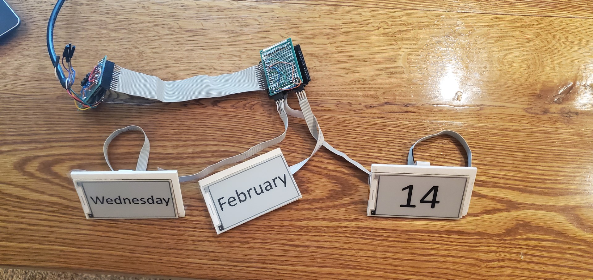
Mechanically, each display is mounted to a 3D-printed plate that pads out the display to the right dimensions, the plate also has screw bosses where the connector boards are mounted. Although the display sizes were very close to the right size, it was unavoidable that some non-displayable area of the panels showed through the front of the calendar frame. To make this look better I made some vinyl frames in a metallic brass/gold color to cover these margins.
(Note: Dates don’t necessarily correlate with actual time/progress since the date was adjusted many times during testing. I also tried several different fonts/styles before deciding on the “FRI FEB 16” format.)
| CPU PIN | Function | Connection |
| 0 | Serial Prog | Prog cable |
| 1 | Serial Prog | Prog cable |
| 2 | ClkInterrupt | RTC |
| 3 | RAM CS | Epaper #1 |
| 4 | EPD2 CS | Epaper #2 |
| 5 | ClkReset | Pushbutton |
| 6 | DateDown | Pushbutton |
| 7 | DateUp | Pushbutton |
| 8 | EPD2 Busy | Epaper #2 |
| 9 | SD CS | Epaper #1 |
| 10 | EPD1 CS | Epaper #1 |
| 11 | MOSI | Epaper all |
| 12 | MISO | Epaper all |
| 13 | LED/CLK | Epaper all |
| 14 | EPD RST | Epaper all |
| 15 | EPD1 Busy | Epaper #1 |
| 16 | EPD DC | Epaper all |
| 17 | EPD3 CS | Epaper #3 |
| 18 | SDA | RTC |
| 19 | SCL | RTC |
| GND | GND/VSS | all |
| VCC | VCC | all |
Apple IIc Monitor Refresh
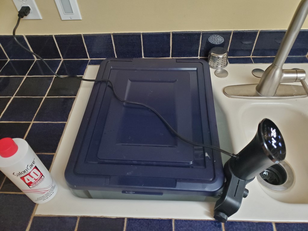
Following-up on the Apple IIc computer refresh, I recently cleaned up the IIc’s monitor. Disassembly of CRTs can be dangerous due to high voltages, but at the point of disassembly it had been unplugged for a few weeks and I made sure to discharge the tube and capacitors as soon as I could. From there it was just a matter of cleaning the plastics, using a magic eraser for scuffs, and de-yellowing. The de-yellowing is accomplished by covering the surfaces in peroxide, putting the parts in bags, and then submerging those bags in a bath of hot water kept warm by a sous vide heater.
A few of the potentiometers for size/position/brightness were dirty, causing the picture to cut out unless adjusted perfectly. This was resolved by spraying some contact cleaner under the knobs and exercising them.
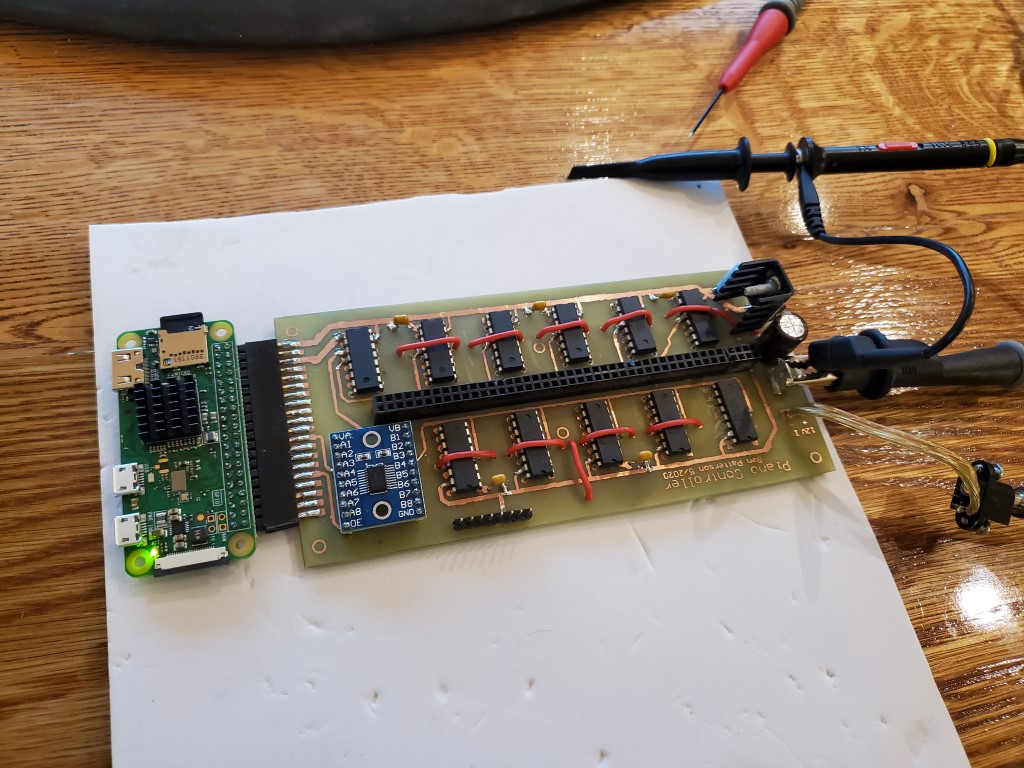
Piano Automation – Valve Control Board Build and Test
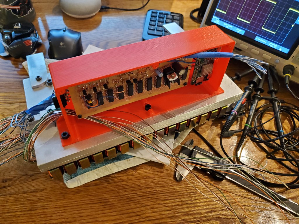
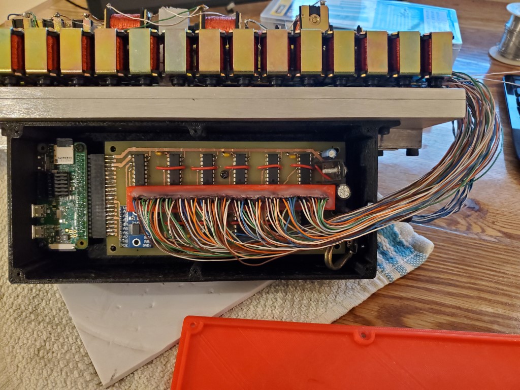
Last weekend I got around to populating and testing the piano valve control board. Unfortunately it did not work when initially powered on, I was able to track this down with a scope to problems with the level shift circuit between the pi and the shift registers. Rather than troubleshoot this farther I ended up re-designing and re-etching the board to replace my transistor array level shifter with an off-the-shelf level shifter sub-board. I also took this opportunity to #1 redesign the solenoid wire connections so that a pin header connection could be used rather than having the wires directly soldered to the board and #2 add a connector to the edge of the board to use the pi’s pin header connection.
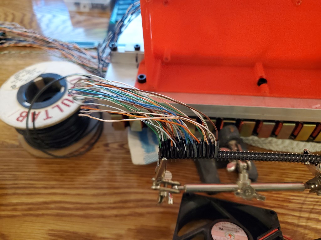
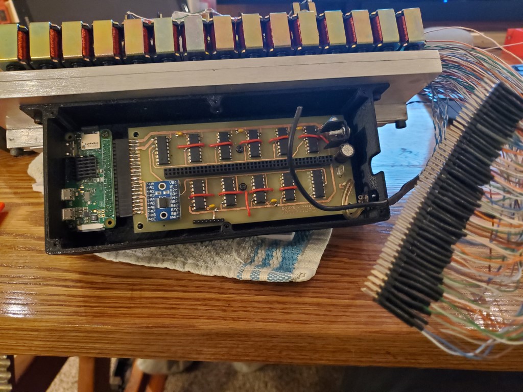
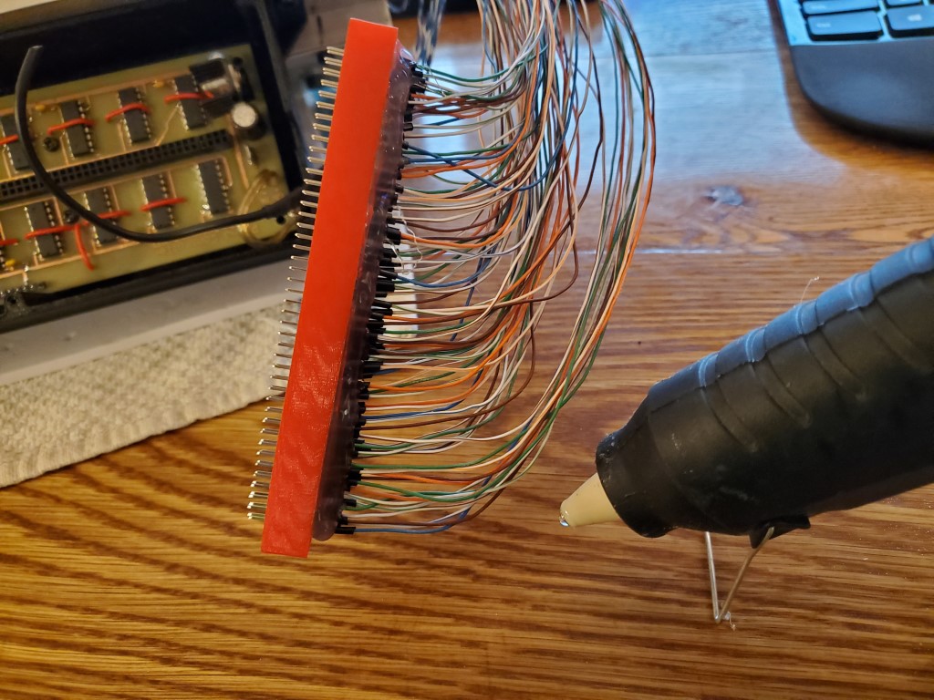
In the mean time I had also created a 3d printed enclosure to hold the board on the back of the valve bank. This was important as it allowed the final solenoid wire lengths to be determined and I soldered all the solenoid wires onto a pin header. I also 3d printed a support ring to stabilize the pin header and hot glued it all together to act as a single strain relieved connector.
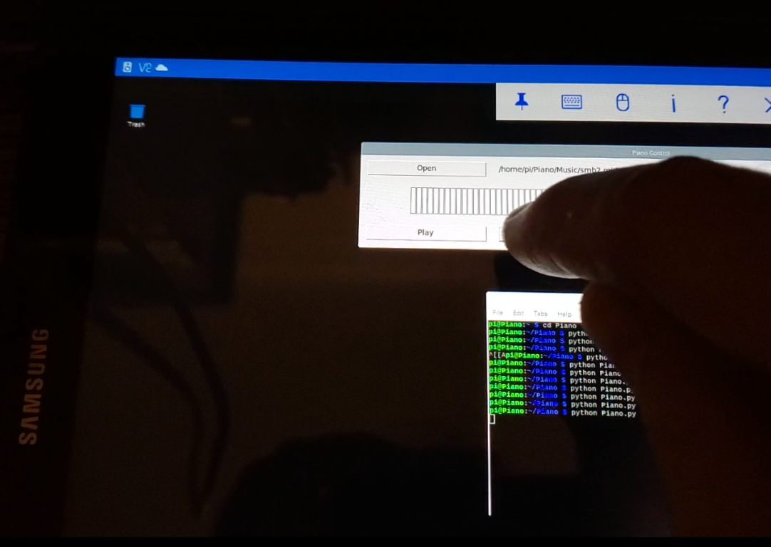
This weekend I was able to finish and test the re-design. All channels seem to be working OK and I’m able to control the piano keys individually from a tablet using a python script. I have some python scripts working that successfully decode the MIDI files, but I haven’t connected the dots between this and the hardware yet, that’ll be the next step along with hopefully adding a web interface.


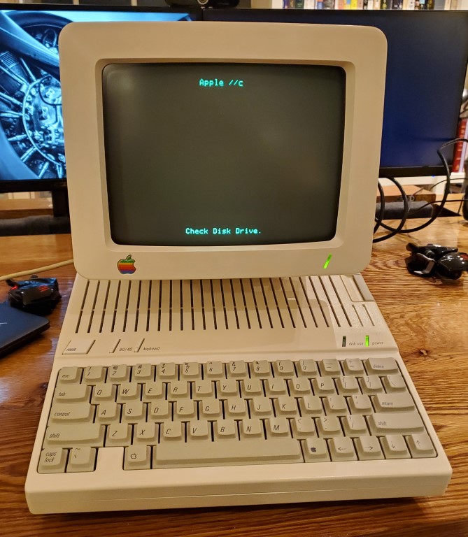
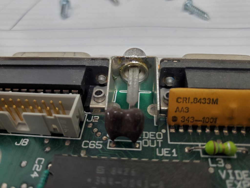
Apple IIc Video Repair
Since moving, the home office area has taken a back seat to other projects. Although it’s been fully functional, there were many unopened boxes filled with books/computers/etc. This weekend we started the process of unpacking and organizing the office stuff with the goal of understanding what kind of storage space and desk space is needed. I’ll use this info to design/build cabinets, hopefully some time in the near future.
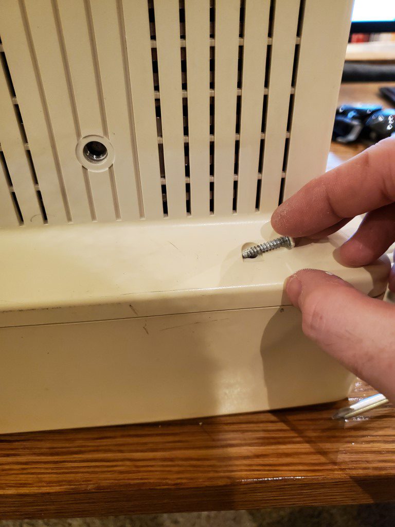
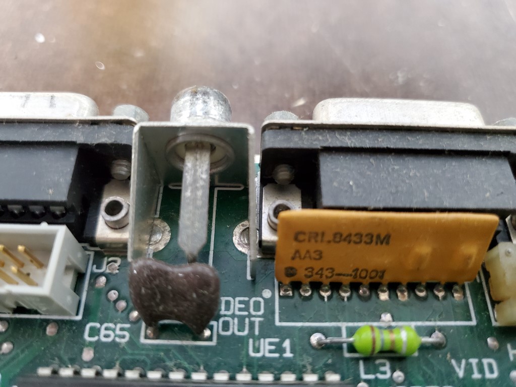
One of the boxes contained an Apple IIc. It powered on OK, but the video signal was flaky. The video connector felt a little loose, so I opened it up and found that the connector design relied on a crimped connection that had worked loose over time. With a very hot soldering iron I was able to heat the crimped connection and flow solder into the joint.
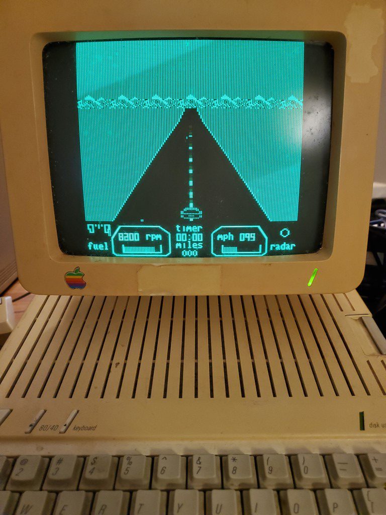
This fixed the video problem from the IIc side, but on the monitor side the brightness knob has to be set just right or the picture scrambles. I suspect the brightness potentiometer has oxidized everywhere except where the wiper was sitting for the last 20yrs. If this is the case, then I should be able to fix the monitor by just spending some time turning the adjustment knobs back and forth until it clears up. Either way I’ll be disassembling both the monitor and the IIc (again) to fully clean them and reverse the yellowing of the plastics; I can replace the potentiometer at that time if needed.
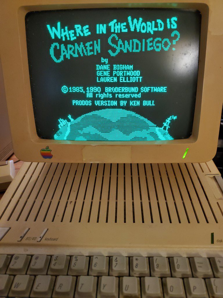
I’m planning to set aside a corner of the office for the retro computers (Apple IIc, Macintosh Plus, Commodore 64). As I unpack these I’ll post more details on getting them cleaned up and working again.
Piano Automation – Valve Control Board
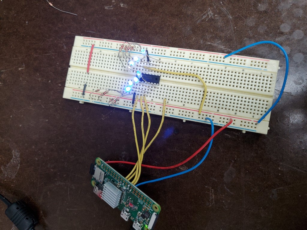
The Piano controller will be based around a Raspberry Pi Zero W. I had originally considered using a spare Arduino, however since the project will require a lot of file handling and a web server, having a full general purpose OS is much easier than shoe-horning it all into the Arduino. The Raspberry Pi also has a wifi adapter built-in, simplifying wiring.
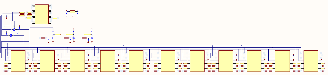
Unfortunately the Raspberry Pi doesn’t have the ~90 outputs that are needed to control the piano’s valves. This is a common problem in electronics and micro controllers – it’s assumed that the designer/integrator is going to provide their own output channels that are most suitable for their device. Instead, the Pi has several low voltage/current outputs that can be switched extremely quickly. I’ll connect these outputs to shift registers, clock all 88 valve bits into the shift register’s ‘memory’, and then send a signal to latch these new values to the outputs. This will be repeated quickly enough (~1000 times each second) that for my purposes the ‘remote’ outputs at the shift registers will appear to instantly follow the valve output commands from software.
74HC595 is an extremely common 8-bit shift register that many examples are based on, unfortunately it’s limited to 35mA outputs at 5V. This could still have worked, but would have required adding a transistor switching circuit to each output to achieve the 200mA @ 12V that the valves require. Going that route would have meant half of the design or more would have been dedicated to individual transistors/resistors, leaving a lot of room for errors during the build. To avoid this I found the MIC5891; this is essentially the same device as the 74HC595 but with built-in output drivers that can provide up to 500mA at up to 50V for each channel. The MIC5891 also has built-in protection for switching the valve’s inductive load, so this selection also avoided the need to add external protection diodes. The only minor problem created by the MIC5891 is that its inputs are all 5V and the Pi outputs 3.3V; this is resolved by a simple FET level shifter.
Once the MIC5891’s arrived I did a quick breadboard test with the PI powering a single shift register with some LEDs. In this test the MIC actually accepted the PI’s 3.3V signals, but I wouldn’t trust this to be reliable and will still include the level shifter on the full board.
To finish the design I added a few FET switches which will allow me to eventually route spare outputs on the Pi through this board to a satellite board that will control the vacuum pump (On/Off/Speed). I also added a 12V to 5V DC-DC power supply so that I can bring a single 12V supply into the control board and have it power everything, including 5V back out to the Pi. This was all drawn up in CircuitMaker.
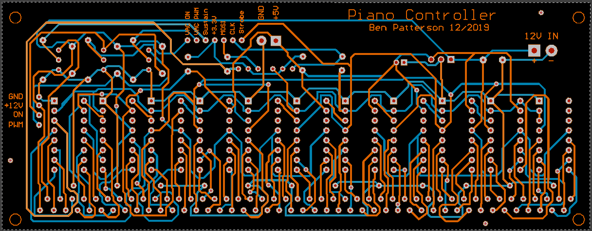
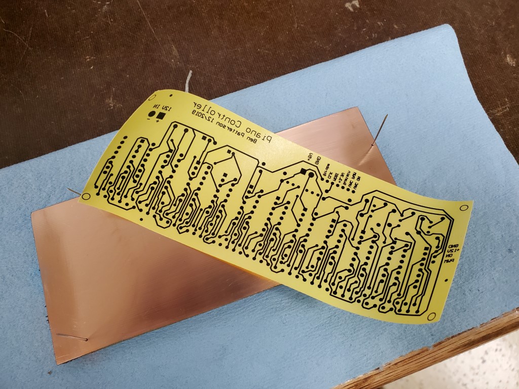
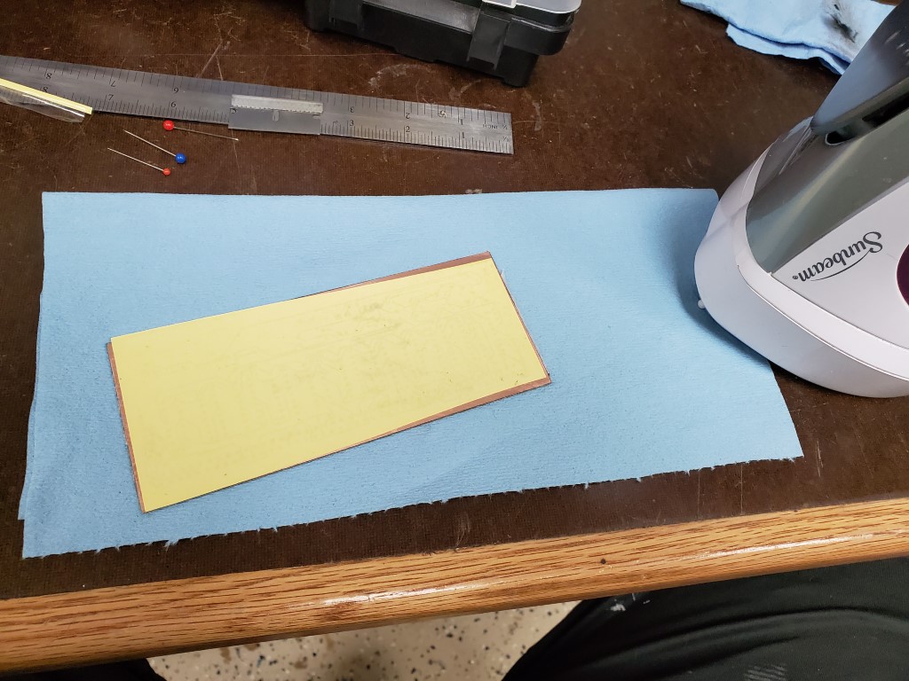
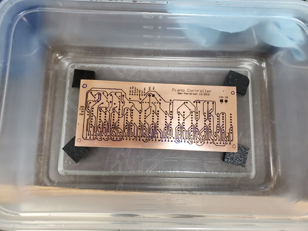
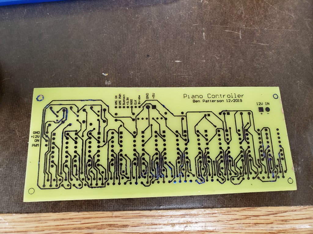
Creating the actual board consisted of printing the circuit design onto toner transfer paper, with scaling 1:1 and with the top layer mirror-imaged. I cut the board blank to size and drilled small holes that I had added to the design as alignment points. The board was then cleaned carefully with fine steel wool and denatured alcohol and then I ironed the transfer paper onto the board. When the board had mostly cooled I pulled off the transfer paper revealing the design. In the past I had used photo paper for transferring toner; this was my first time using purpose-made toner transfer paper and it definitely was much better – the board only required minor touch-up with a fine tip marker prior to etching. After etching in Ferric Chloride, steel wool and denatured alcohol were used to clean the toner/marker from the board.

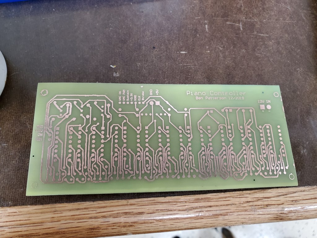
The next steps are to drill all the pin holes and to fully tin the board to increase the ampacity of the traces and prevent corrosion, I’ll do this prior to populating and testing the board.
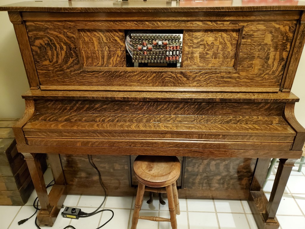
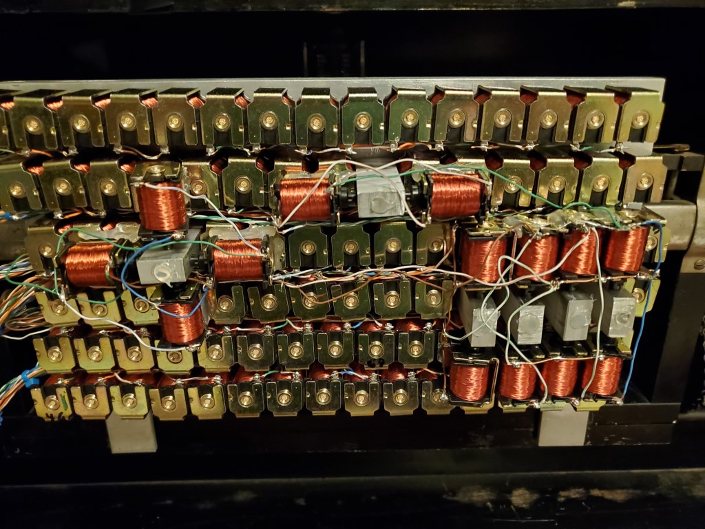
Piano Automation – Valve Manifold Complete
This weekend I had a chance to test the completed valve bank.
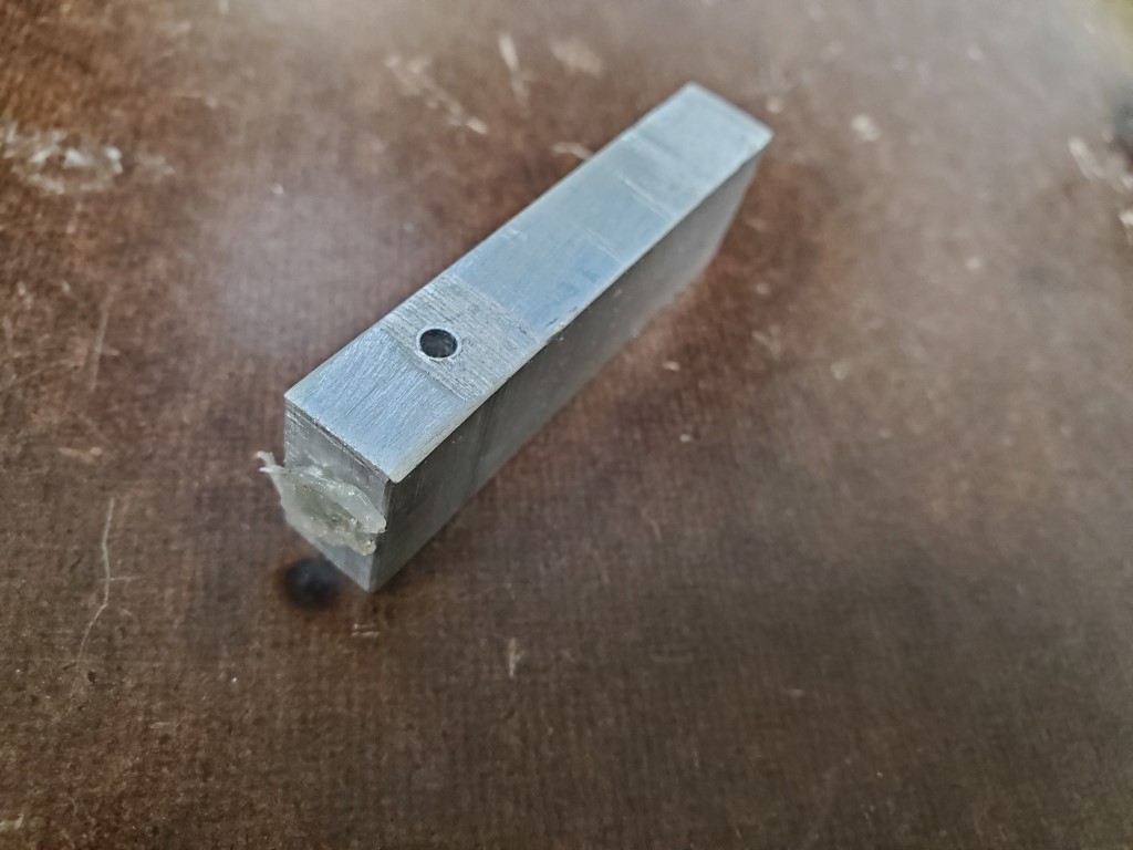
Testing revealed that some of the keys did not actuate with their corresponding valve open. On these keys when the valve (while turned ON/open) was removed from the manifold the key would strike immediately, pointing to lack of airflow through the valve as the cause. I can’t explain why this occurs on only some of the keys but the piano turns 100yrs old next year, so the inconsistency isn’t surprising. The piano could perhaps be adjusted to make these keys work the same as the rest, but I could more easily just provide more airflow via multiple valves per key – this is the approach I took. To connect multiple valves per key I created a few hollow standoffs that fit inside the valve holes in the manifold . The standoffs then have holes on their sides to allow connecting the extra valves on a 2nd layer above the rest. The end of the hole that was drilled to hollow the standoff was sealed with hot glue. Two valves solved the problem for most of the offending keys, but one extra special key required 4(!) valves in a ‘+’ configuration.

With the mechanical parts complete I’ve taken the first steps to construction of a raspberry-pi based controller that will use shift registers to power the solenoids. The raspberry pi and associated circuitry will be small enough to fit on the back of the valve manifold in the area where the paper roll would normally be. It has wireless connectivity and I plan to have it host a webpage where it can be controlled by phone/tablet. I’m bread boarding this first to prove the concept with one shift register, then once testing is complete I’ll create a circuit board to hold all 11.