S4 Coolant Leak Tool
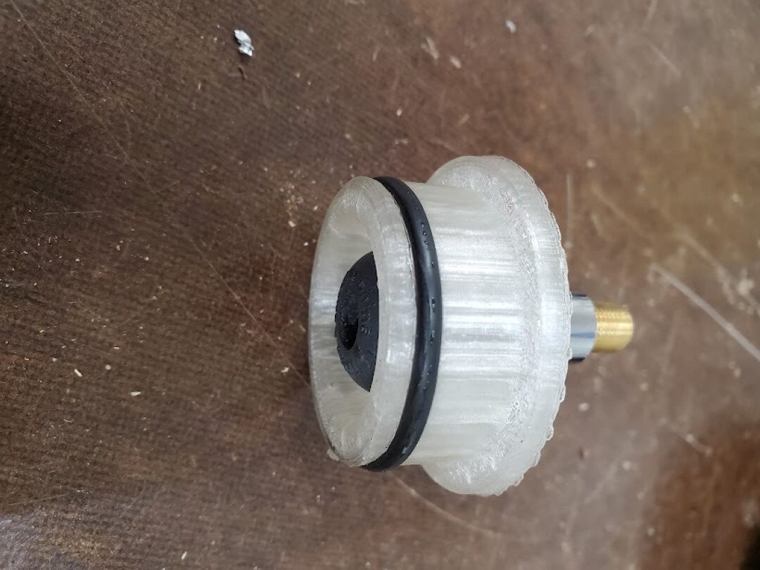
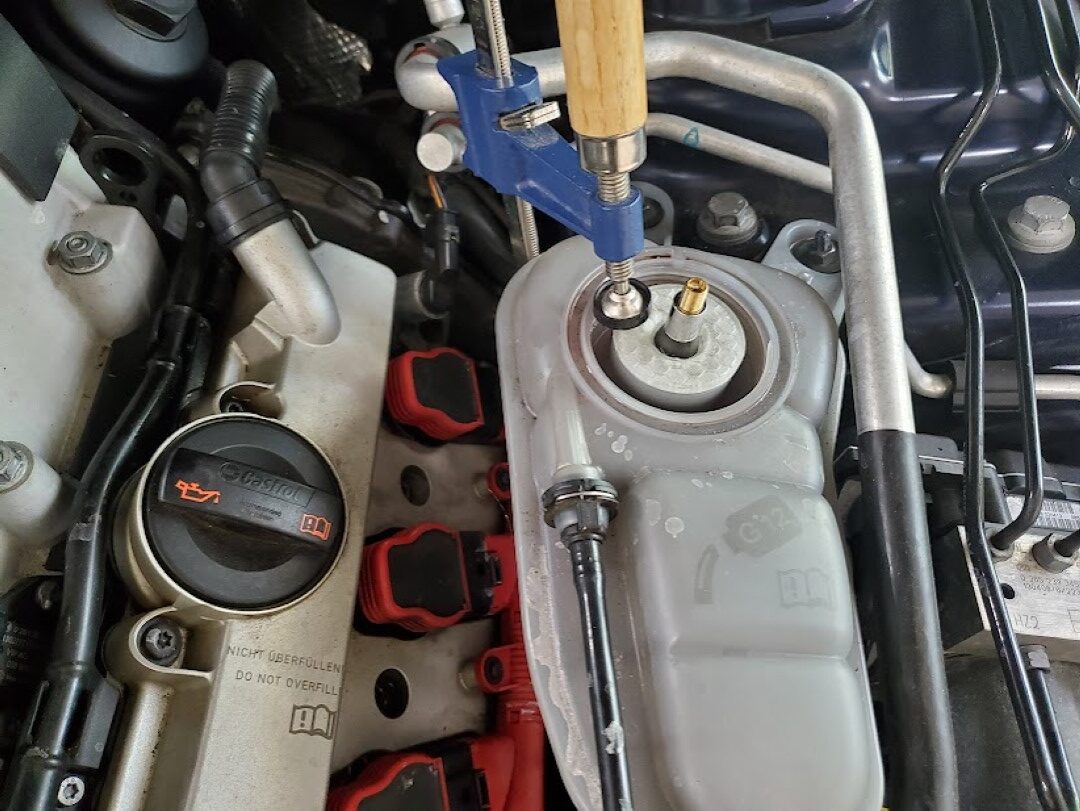
I noticed a small coolant leak on my car recently. It wasn’t clear where it was coming from, only that it was somewhere in the front and only occurred after running for some time. To help troubleshoot this I created a 3d printed adapter that interfaced a tire schrader valve to the coolant tank, sealed with an O-ring. An F clamp held this adapter in place and I pressurized the coolant system to a few PSI. This lead to the discovery of a bad O-ring on one of the coolant crossover pipes at the supercharger, which was easily fixed.
Audi S4 3.0T Secondary Air Cleaning
Part 1: Background
A while ago my check engine light began coming on sporadically, after scanning I found this was related to P0491 & P0492 errors. These errors indicate that insufficient airflow is available to the secondary air system that’s responsible for getting the exhaust catalysts up to temperature quickly at start-up. These errors would self-clear, but over time the light stayed on longer until eventually it stayed on.
I first checked all the ‘easy’ stuff related to this fault: the secondary air pump and solenoid both worked OK via VCDS and no leaks were found on any of the tubing. I also tested the “combi” control valves which successfully blocked air flow when blowing through the secondary air pipe and allowed air when manually actuated with a vacuum pump. At this point I ran a good amount of seafoam and intake cleaner through the secondary air pipe that goes under the supercharger, using a HVLP paint blower to push it through the system while the combi valves were held open with vacuum – lots of smoke, no change.
This unfortunately left blockages in the cylinder head’s internal secondary air ‘manifold’ as a most likely cause for the problem, there’s a TSB with lots of good info here: https://static.nhtsa.gov/odi/tsbs/2018/MC-10153120-9999.pdf (Required Reading for this topic!)
Options at this point, in order of consideration, were:
#1 – Take it to the dealer for the 120k mi extended secondary air warranty, I had ~110k mi at that point. I strongly considered this, but in the end it didn’t seem worth the hassle. With it being high mileage by their standards I fully expected to get push-back or some excuse for it not to be covered, while potentially being on the hook for their ‘diagnostics’ fees. Either way this was likely to be a less enjoyable experience than wrenching in the garage over a long weekend.
#2 – Buy the VAS6825 tool and do it myself. The TSB has plenty of info to do the job successfully, OK let’s just order the tool and …….. it costs how much?!?!
#3 – Make the tool myself and do it myself. The tool is simple enough, and I was reasonably confident a usable tool could be made at home. I went with the last option, let’s make the tool….
Part 2: Tool Creation
From photos online, the official tool (fig. 1) appeared to just be two smallish diameter flexible pressure washer tubes: one that’s basically a tiny sewer jetter, spraying forward, and the other that sprays out sideways. The main passage can be cleaned manually (coat hanger, vacuum), so only the sideways spraying tool is needed. The sideways spraying tool also comes with two plates, a bushing, and an attached scale to correctly position jet in front of the perpendicular passages while still allowing some movement for wiggling the jet around for better cleaning. For my purposes the whole bushing, plate, and scale arrangement would also be omitted – I’d be using a camera to locate the distance to the passages and then positioning the tool manually. There’d be no damage risk from a misaligned jet, as water doesn’t cut aluminum at 4000psi, so the water would just come squirting back out around the tool. I assume the official tool only has the extra complexity to justify its exorbitant price and to make it more suitable for use in a professional environment.
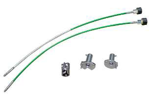
Figure 1: Official VAS6825 tool
With that settled, I only needed a long tube with a right angle nozzle. The small diameter pressure washer hose they use for this isn’t commonly available and even if it were its not clear that any fittings would fit inside the passage. (They use a crimp connection to get around this, but that’d require expensive crimp tooling in the strange tubing size – big money for something that I’d likely never use again). The good news is that the main secondary air passage is perfectly straight, so there’s no reason for flexibility at all. With this in mind the plan quickly coalesced around using some steel tubing. The tubing I selected was a 3ft length of 3/8″OD with 0.083″ wall thickness (McMaster 89955K459). This thickness is massively overkill vs the 4000PSI of my pressure washer, but a big ID isn’t needed for flow and I was more concerned with having enough metal thickness to get good welds.
From there I took a spare chunk of 1/2″ round bar, bored a 3/8″ hole to accept the tubing, and tapped the other side to 1/4″NPT for the pressure washer coupler. (fig. 2) I did this on a lathe, but it could be done with a drill press or drill/vice if centered carefully. This was then welded* to the tube on one side along with a simple plug on the other.(fig. 3) At that point I had a fully sealed tube to which I drilled an ~0.043″ hole on the side of the end, giving me the right angle jet. (fig. 4) The hole size depends on the specs of the pressure washer, check tables online, 0.043″ was right for 4000PSI / 3.5GPM. The official tool appears to have 3 holes – I suppose you could calculate the right hole sizes for this and do it that way, but the single hole is already tiny and any performance loss from this is easily overcome by wiggling the single jet around more/longer. Lastly, add a line along the tool so it’s clear which way the nozzle is pointing. Total cost less than $30.
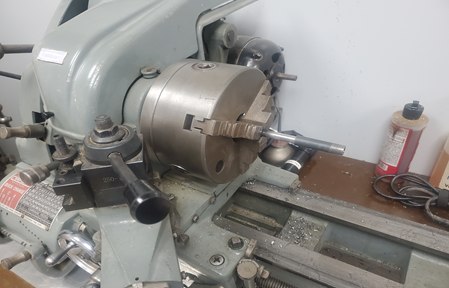
Figure 2: Making the end adapter
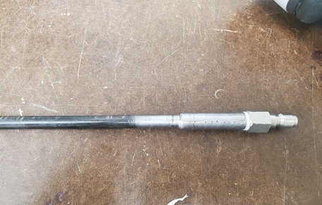
Figure 3: End adapter welded to tube, coupler fitting attached
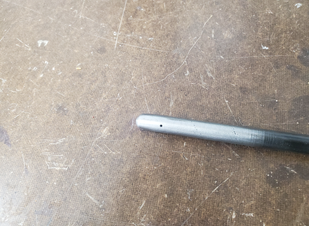
Figure 4:Nozzle Orifice Drilled
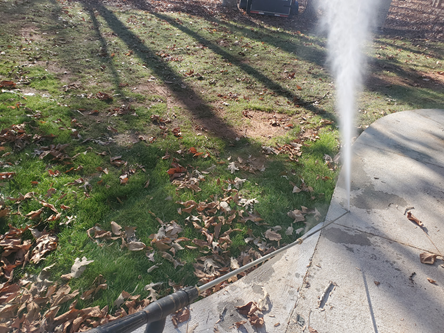
Figure 5 : Testing
*Warning: This is effectively a DIY hydraulic line under a few thousand pounds of pressure. It can
fail forcefully with risk of injury.
Part 3: Cleaning
As always, remove the entire front of the car using whatever method/sequence you prefer. You’ll need unobstructed access to the front of the engine. I was able to suspend the bumper/radiator support from the ceiling and hinge it open like a gate to avoid disconnecting the AC lines. Note though that this puts strain on the upper radiator hose and that will crack the coolant crossover pipe, so disconnect it first. I only left the hose connected because I couldn’t get it off the pipe without destroying it, so it was probably doomed either way.
Get access to the secondary air ‘manifold’ freeze plugs (fig. 6); there are a number of things in the way (belts, coolant flange, hoses, etc) but if you’ve gotten this far you’ll figure it out. Pop one side of the freeze plug with a drift punch and it’ll rotate so you can yank it out with needle nose pliers. Remove coils and plugs at this point also.
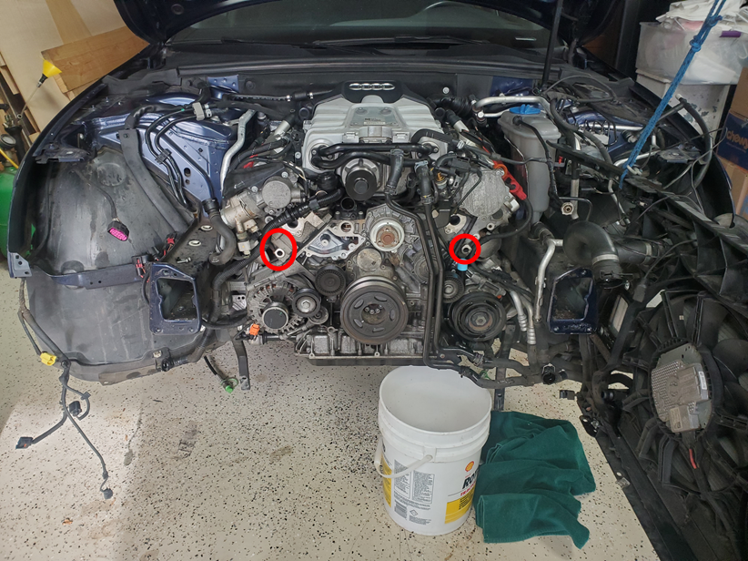
Figure 6: Secondary Air Passages from the front of engine
Next use the right angle camera mirror to find the air passages with the angle of the exhaust manifold flange for reference. The passages are drilled straight from the flange (where they dead-end) up to the back of the exhaust valves. Point the mirror up in that direction, it’s the part of the passage that goes up into the valve that we want to clear, the other part that dead ends onto the back of the exhaust flange is only there because it’s much easier for them to manufacture the head that way. Once the passage is centered in the field of view mark the camera cord where it enters the cylinder head, I used colored electrical tape with different colors for each bank; repeat for all 6 passages. (fig. 7) Reference measurements in table 1.
| Driver (US) | Passenger | |
| Front | 75mm | 45mm |
| Middle | 165mm | 135mm |
| Rear | 255mm | 225mm |
Table 1: Distance from Port Edge to Passage Center
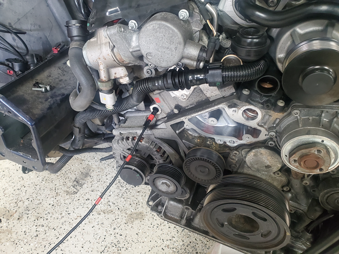
Figure 7: Marking the individual passage locations
Warning: Make sure the camera body is securely attached to the cord! Even though my camera (depstech) appeared to be one piece it decided to separate – the cord pulled out and left the camera guts and front body in the passage. This could be disastrous as you’d then need to drop the transmission to pull off the combi valve to push the camera body out from the other side. I was extremely lucky this happened close enough to the end that I was able to access it with small needle nose pliers and pull it out. It re-assembled no problem, the cord had a connector inside the camera body. After that I epoxied the cord to the camera body and wrapped them together with electrical tape for extra insurance.
Next put the camera and cleaning tool next to each other with the mirror and nozzle orifice aligned and transfer all the markings onto the cleaning tool.(fig. 8) All that’s left at this point is to drop the exhaust before the catalysts, setup a big storage container to catch the water, insert the tool, and start blasting. (fig. 9) You’ll also want a catch container up front under the tool, drape a wet rag (if it’s dry it’ll blow away) over the tool so that the water coming out will hit it and drop into the catch container. Insert the tool to the depth of the first marking and rotate so the line on the tool is facing the right way (the same angle you found the passage with the mirror). Set a timer for 3min and pull the trigger. You’ll get an initial blast of dirty water from the main passage as the jet eats through the blockage, this should pass almost instantly. If it doesn’t, you’re off-target – try rotating and moving the tool in/out until water stops blasting out of the front. It’s very apparent when you’re on-target, no water comes out of the front and there’s a satisfying gurgling noise. For the remainder of the time I just moved the tool in/out and rotated back/forth, changing direction when water began coming from the front. Repeat for all passages.
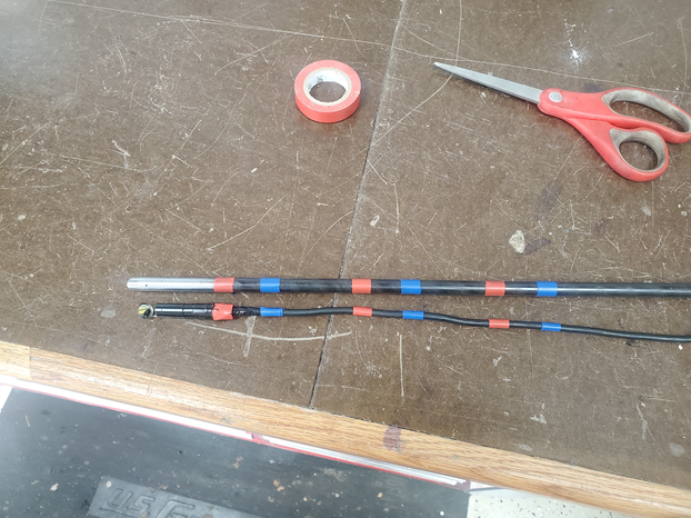
Figure 8: Transferring passage depths to cleaning tool
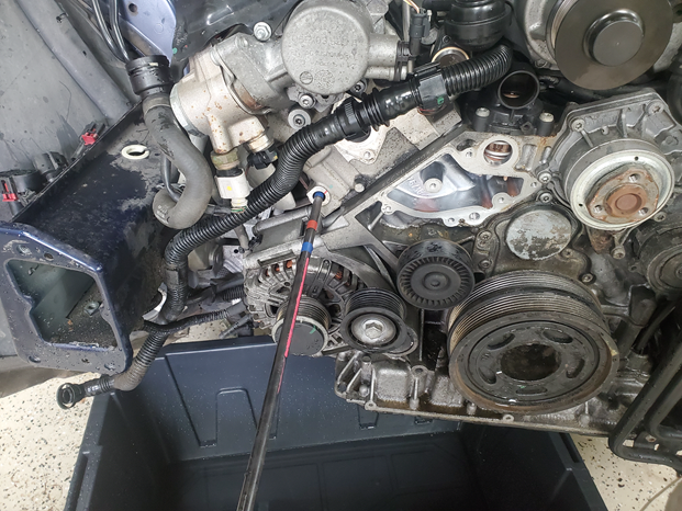
Figure 9: Blasting! (not shown aligned)
Once complete, use a vacuum extractor to try to pull water from all the plug holes. It was clear during blasting that one exhaust valve was open on each bank, and these two cylinders did have a little bit of water. Next crank it a few times with the plugs out as a precaution before fully reassembling and clearing all the codes.
The camera had a hard time focusing on the clogged ports, I had to really work to get usable pictures but you can see a very small dark area in the middle of the before shots – I believe these were the only open area and you can definitely see the edge of the port, so everything in-between was crud. (fig. 10) After cleaning I got great pictures with no effort at all that immediately showed fully clear. (fig. 11) The process was a success and the code has not returned as of many months later.
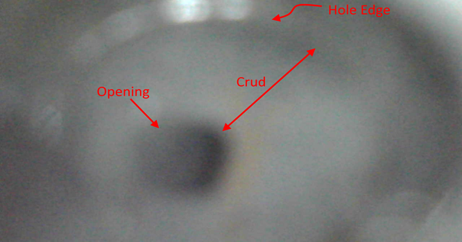
Figure 10: Typical Passage Before Cleaning
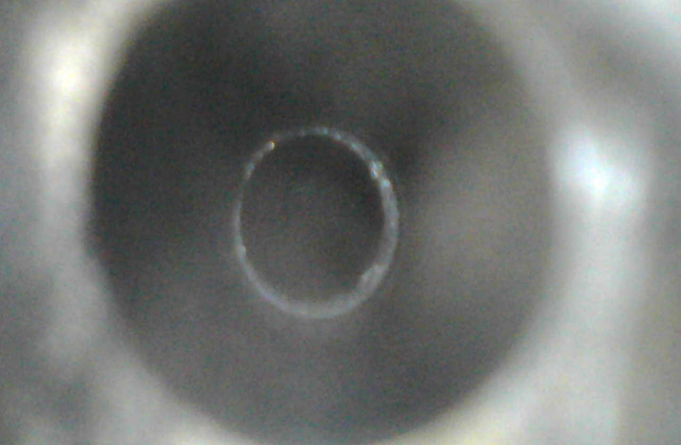
Figure 11: Typical Passage After Cleaning
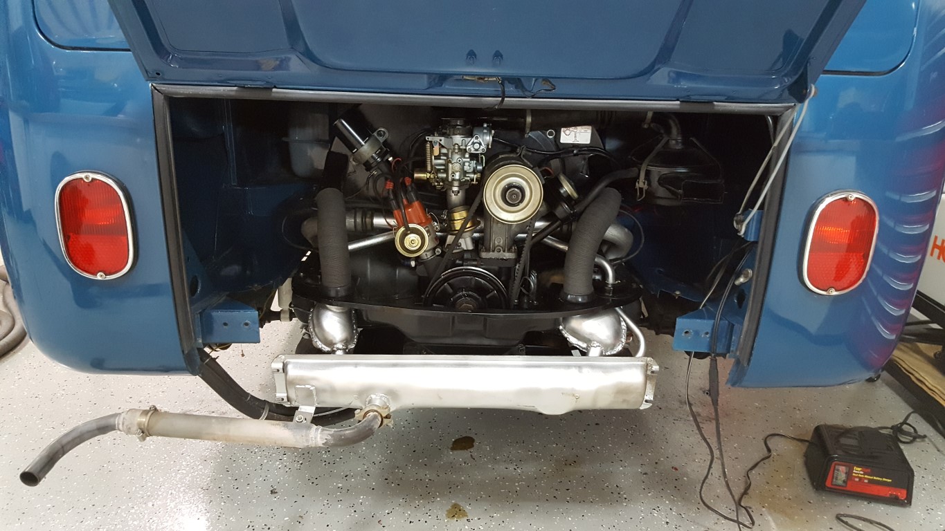
Bus back together
This weekend the transmission arrived and I got everything back together. While waiting on the transmission I completed a few miscellaneous things:
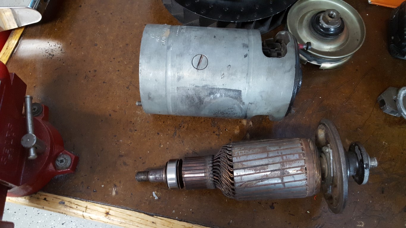
- Replace bearings in the dynamo/generator (it’s not an alternator like in ‘modern’ cars)
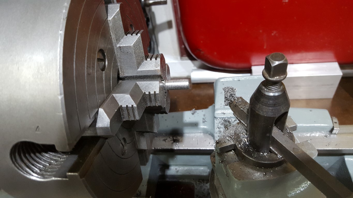
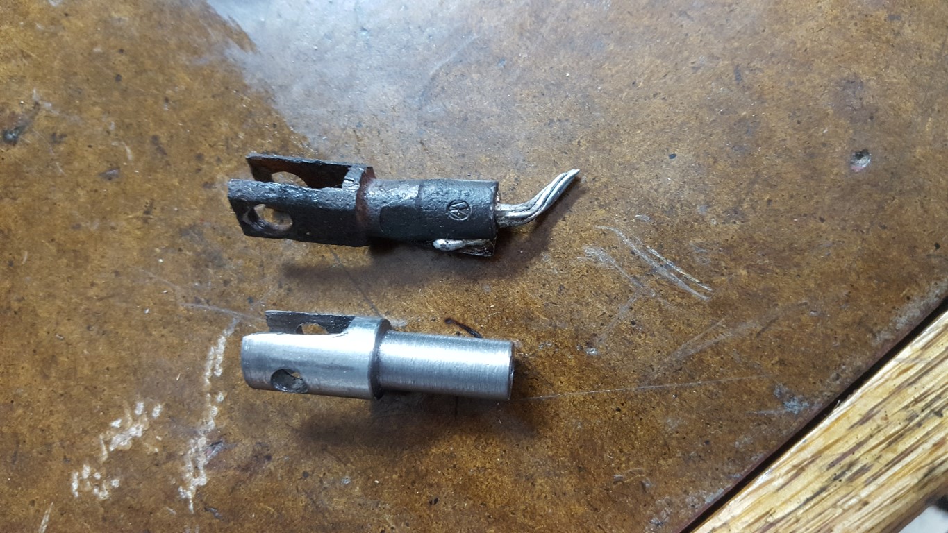
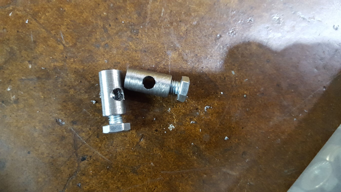
- Fabricated replacement clutch cable, including making a new end link on the lathe. The end links were then crimped onto the cable with the 12 ton hydraulic press and soldered in place, so they shouldn’t be going anywhere.The clutch cable had partially broken and was stretching with each press, causing the clutch not to disengage all the way. This is what took the bus out of commission in December. Since it was still connected at both ends and not completely loose it seemed OK until I removed the pedal pan and saw many broken wires.
- Fabricated the special barrel nuts needed to connect the heater control cables to the exhaust heater boxes.
The test drive went very well, it’s noticeably smoother but noise levels are still quite high inside. Part of the noise level is a minor exhaust leak that I’m tracking down, but the new smoothness also allowed me to notice for the first time that a majority of the noise is from the axle reduction boxes. This was confirmed by carefully running in 2nd gear with the back wheels on jack stands – the bearing rumble then became even more noticeable. Replacement bearings are on the way and I should be able to swap them out with the engine/transmission still in place.

Bus Engine Rebuild – Part 2
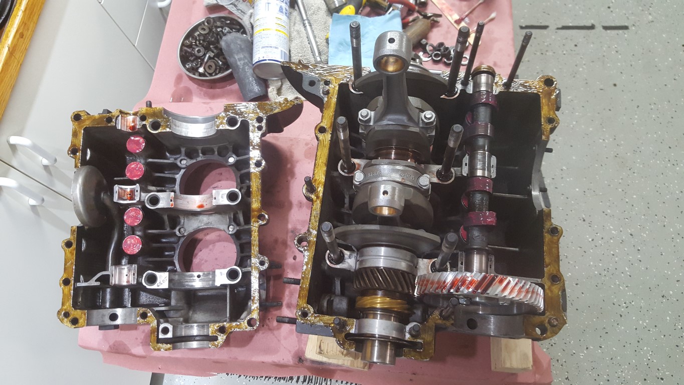
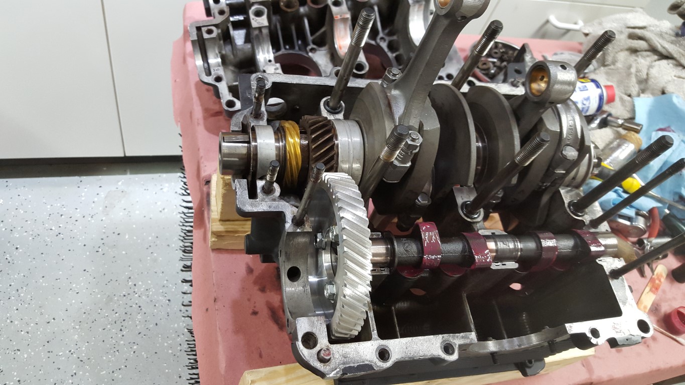
This weekend I started putting the engine back together, and I’ve decided to replace a number of parts:
- Camshaft – A few of the lobes were worn down, limiting valve lift. Replaced with a very mildly modified cam that will provide more power to go along with the new higher transmission ratios.
- Lifters – Lifters had worn slightly concave rather than the correct slightly convex.
- Connecting Rods – All rods weighed the same but were not balanced end-to-end and there was not enough material left to grind off and correct the problem.
- Bearings – The bearings were OK but it’s easy enough to replace these while the case is open.
- Pushrod Tubes – These could have been reused but were a little beat up and now is an easy time to replace, ensuring no leaks.
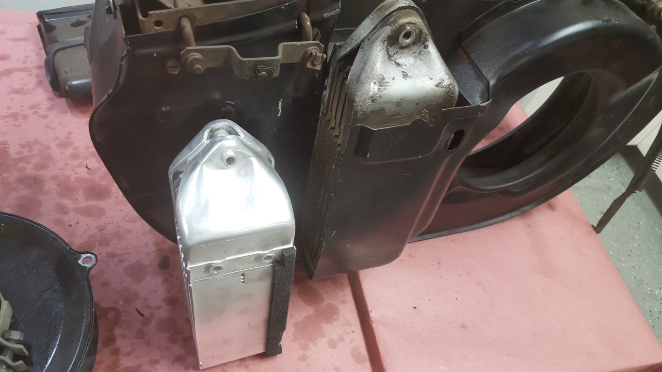
- Oil Cooler – The old cooler was made in 1971, no telling how much build-up there was inside preventing heat transfer. Replaced with a larger cooler from a later engine style.
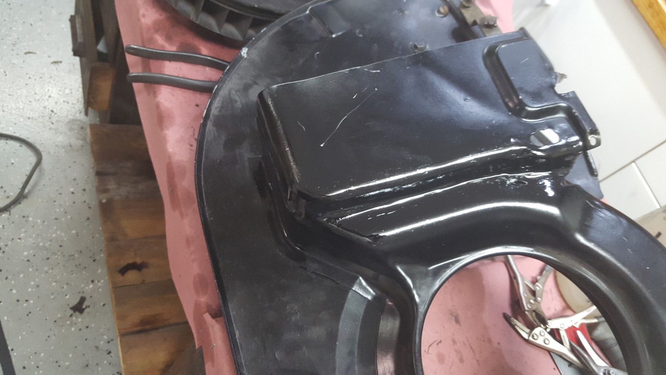
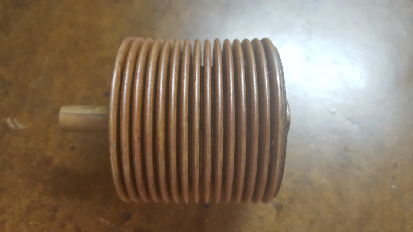
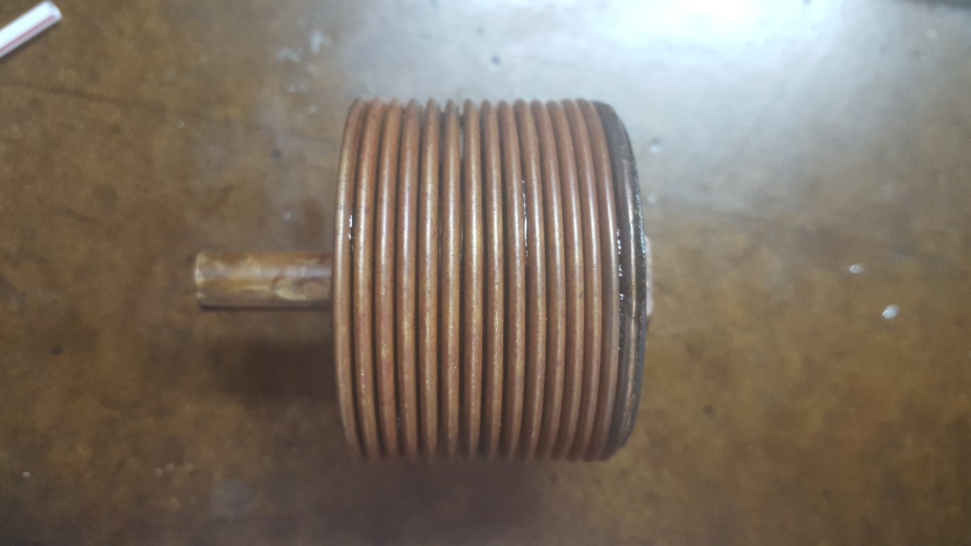
It’s mostly reassembled now, including shimming the crank/flywheel for proper end play and verifying with a dial indicator to 0.001″ (end play is critical on aircooled VW’s). I also modified the fan shroud to accept the bigger oil cooler and also re-built the thermostat. The thermostat is a sealed copper accordion that expands when heated. For some reason mine had expanded permanently; these are no longer made and becoming increasingly rare, so I had to fix it. Luckily I was able to find information about others who have had the same problem and I was able to fix it in the same way; the fix consisted of unsoldering the end plate, compressing the accordion, dropping in a bit of rubbing alcohol, and resoldering the plate before it had a chance to evaporate. The thermostat is now completely contracted at room temp and begins to expand around 80°C, allowing it to push on a linkage that opens cooling flaps in the fan shroud.
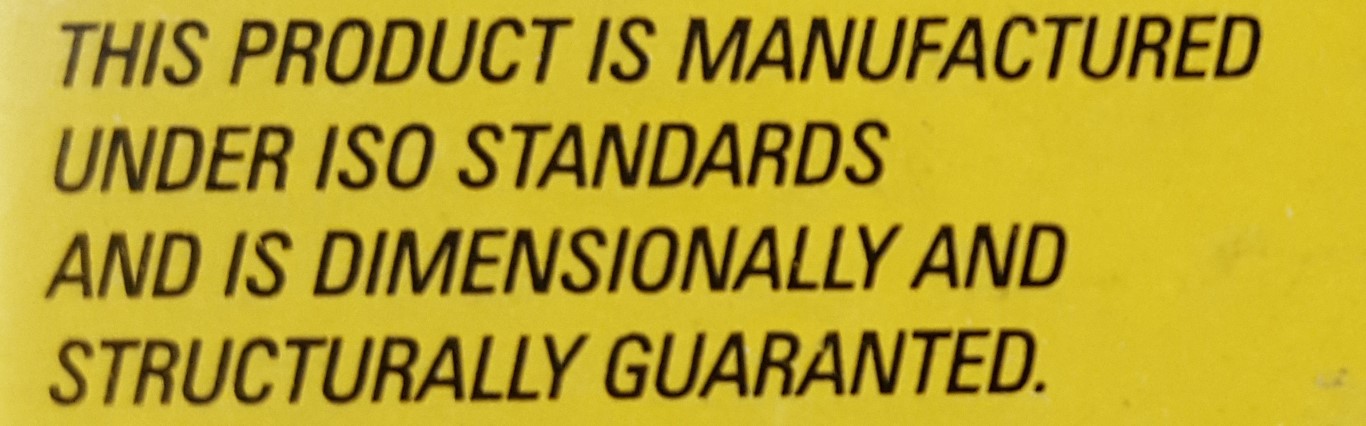
The new bearings are “structurally guaranted[sic]”, hopefully that’s just a typo and not a clever way to dodge claims – “they weren’t guaranteed, they were guaranted”
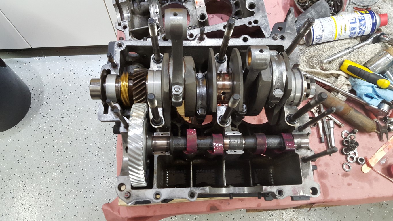

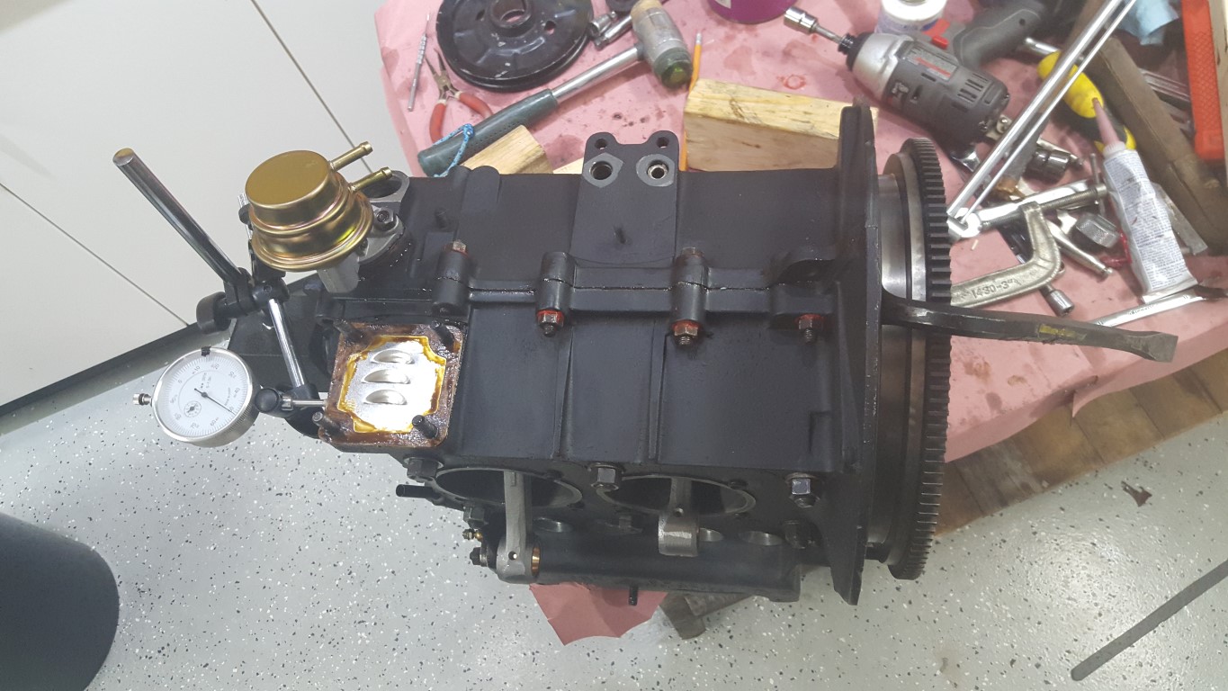

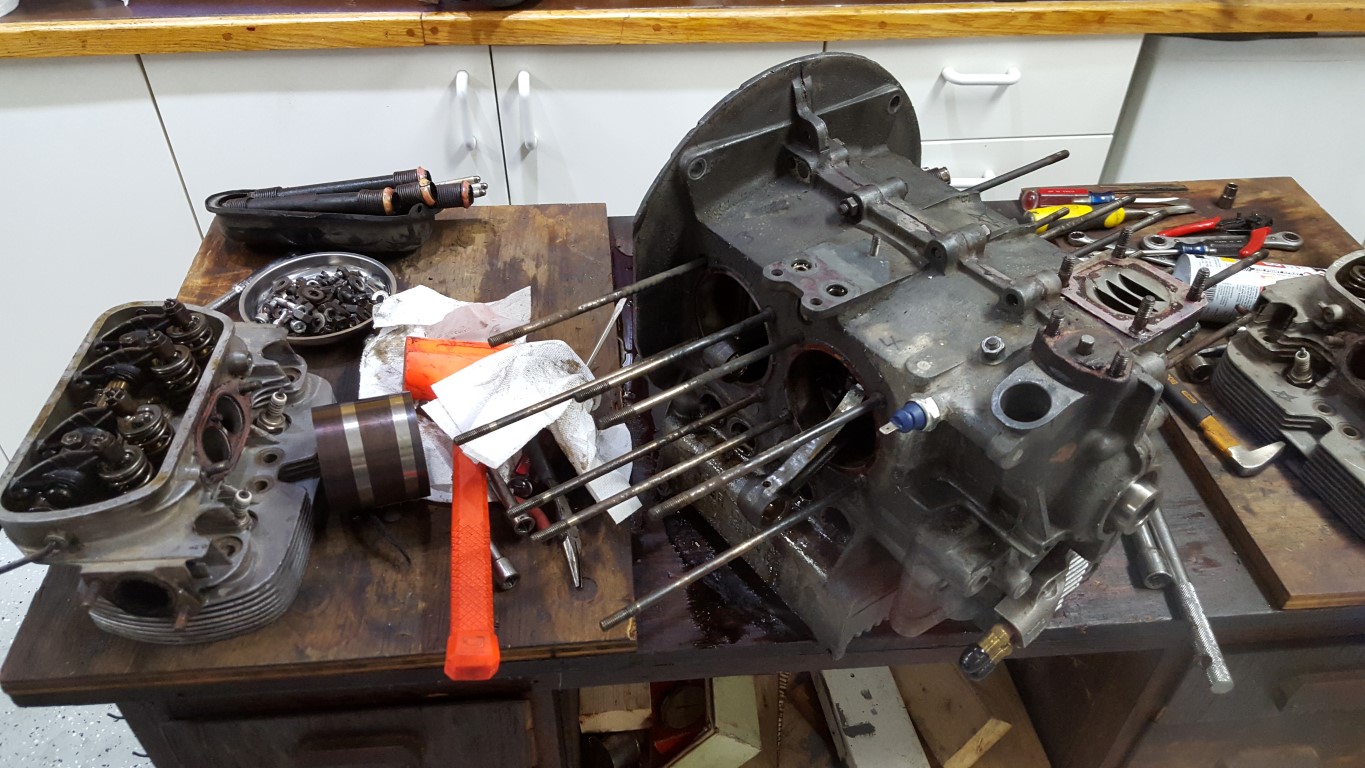
Bus Engine Rebuild
A slight change of direction with the transmission rebuild. I was looking forward to going through the transmission and readjusting everything to make it work again, but to get more speed I would have needed to swap out the ring/pinion gear as well as 4th gear. The cost for these gears separately was not too much different from the cost of a rebuilt transmission that included these gears. Because of this, there’s a rebuilt transmission on the way that already has the ‘correct’ gearing. Since this is a hobby I normally don’t think about time too much, but this also buys me a lot of time that gives me a chance to instead go through the engine while I’m waiting for the transmission to arrive.
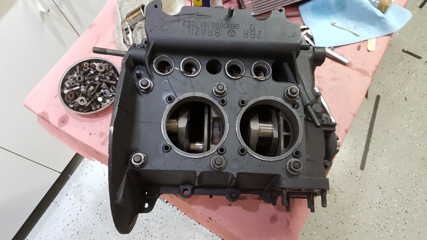
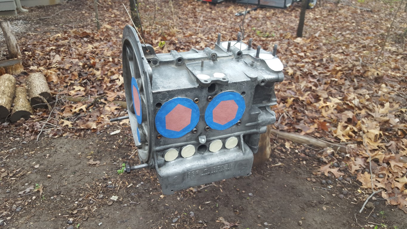
I started going though the engine this weekend. There wasn’t anything necessarily ‘wrong’ with it, but it was put together somewhat hurriedly prior to having the bus at the wedding; I’ve since had a chance to second-guess a few things I did, especially with balance. I stripped it down to the case and this time gave it thin coat of black paint; heat has been an ongoing issue and changing the color to flat black will actually improve heat dissipation slightly. Overall everything looked good, bearing wear looked normal.


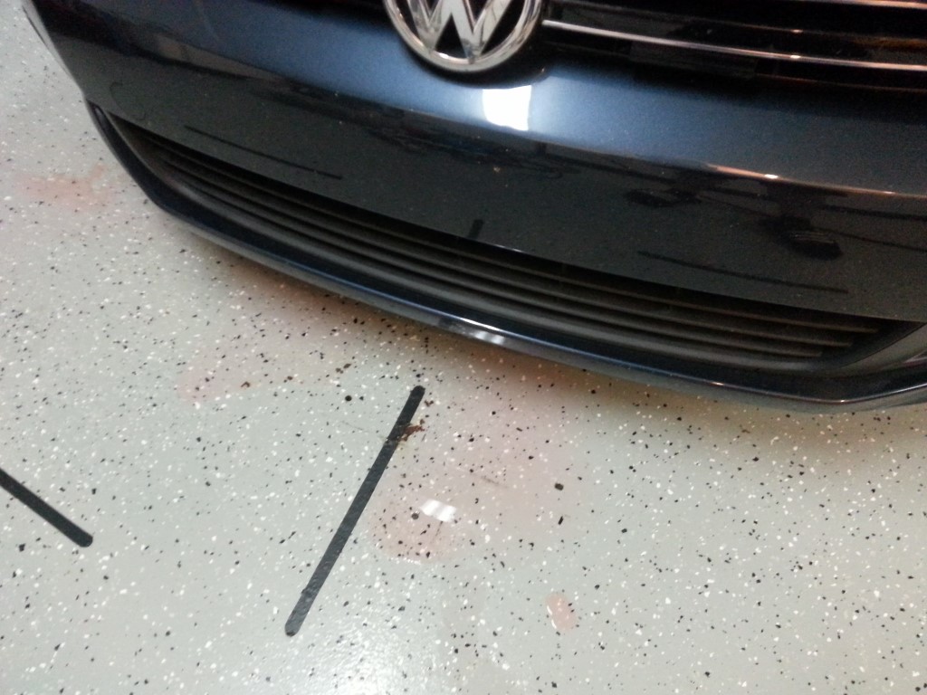
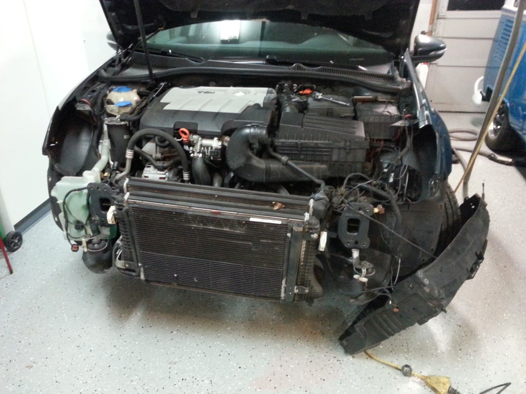
Golf Coolant Leak Repair
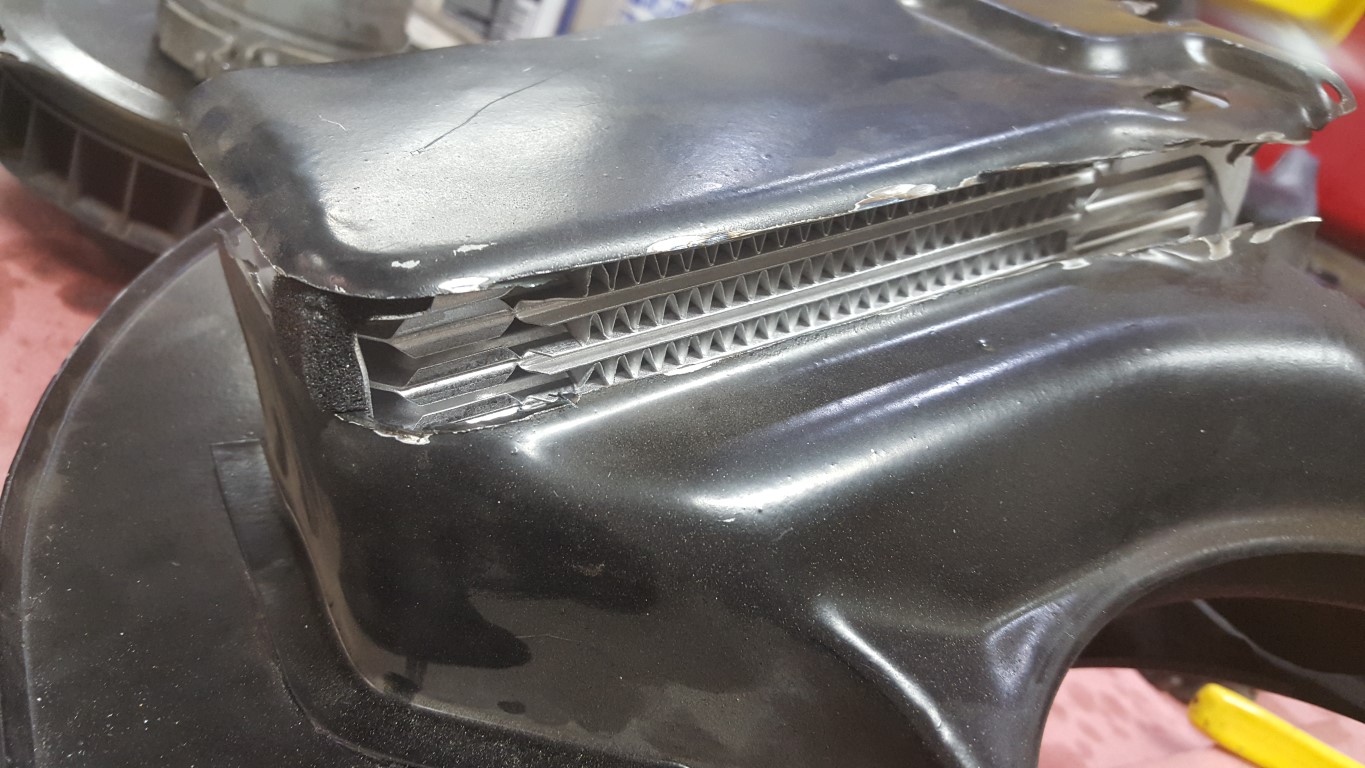
A few weeks ago the Golf gave a low coolant warning and, not seeing any immediate signs of a leak, I topped if off. This week, I noticed a few pink drips in the garage. This is actually fortunate because it meant there was an external leak of some kind rather than something more serious like an EGR cooler or head gasket leak. Since the puddles were rapidly increasing in size I investigated the source of the leak tonight. Unfortunately it wasn’t anything as easy as a bad hose, clamp, or o-ring; I could see coolant dripping from the radiator. The next step, as it is with most modern VW repairs, was to disassemble the entire car. Although it looks intense, cleaning up the garage prior to starting this project took about as long as actually accessing the radiator.

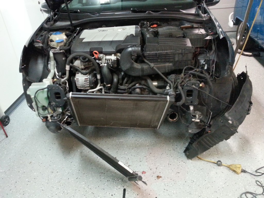
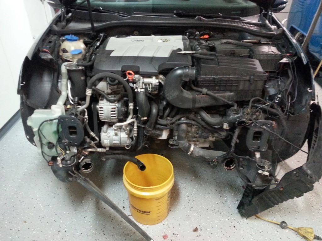
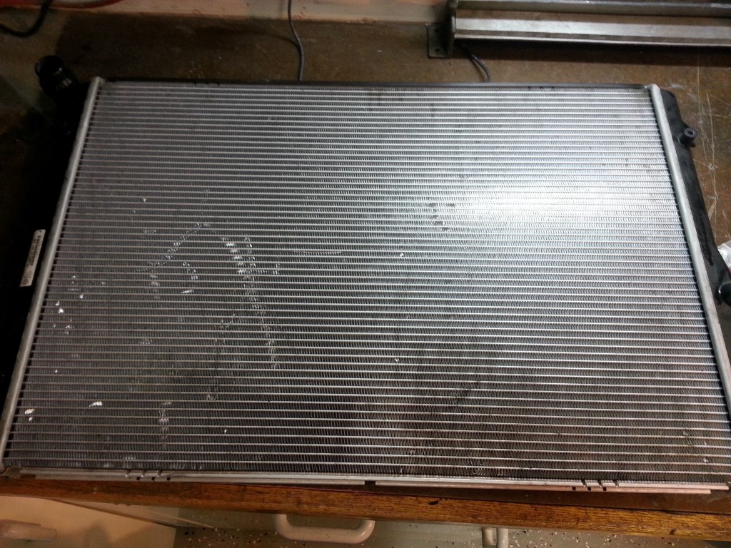
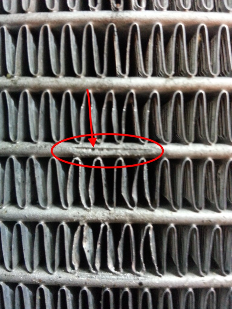
From searches online it appears this is a somewhat common problem; the fan support vibrates against the thin aluminum radiator tubes until a hole is worn through. During reassembly I’ll add some rubber cushioning in this area to prevent recurrence. A replacement is available locally and I’ll pick it up after work tomorrow; I should be able to have everything back together tomorrow night, though I may let the project stretch into the weekend to thoroughly clean/detail the front bumper while I have everything apart.
Update: Finished this Friday night, relatively easy, no more leak.
This Weekend
This weekend I fixed the timing problem and it’s 100% better than it was. In search of lower temperatures at high speed I also changed to 5W20 oil; unlike watercooled engines that regulate their temperature directly with a thermostat, the VW aircooled engines primarily regulate their temperature indirectly via oil pressure. When the oil is cold it’s slightly thicker, causing the oil to compress a spring loaded valve and bypass the oil cooler; once it heats up it becomes thinner, allowing it to flow through the oil cooler in the fan shroud. In this way, the oil temperature is kept under control. However, if the oil pressure is too high even when hot, the oil will still bypass the cooler. In my case the oil pressure is high due to tight bearing clearances from the new bearings, and high RPM. It may get better as the engine breaks in, but for now I’ll just keep it at 55MPH or less except short bursts; the real solution here is getting the RPMs down with different transmission ratios. I also made good progress toward wetsanding and polishing, and got vinyl on order for all interior panels and seats.
“Timing is Everything”
Since the rebuild I’ve had trouble getting the bus to do 65 for more than about 5 miles without getting into the danger zone of overheating. I’ve looked at various things in the process of debugging this but tonight I think I finally found the problem; and it’s related to the way that the ignition timing works…
(Begin technical rant, or just skip to the picture at the end) To adequately explain the problem I first have to explain that in an internal combustion engine the spark is timed so that the explosion in the cylinder is peaking just as the piston is beginning to move down; the explosion pushes the piston down, which ultimately moves the bus. However, the explosion is a chemical reaction, and it takes roughly the same amount of time to occur regardless of how fast the piston is moving; so when the piston starts to move faster (higher RPM) you have to start the explosion sooner to keep the explosion peak at the same place in the cycle. This moving of the spark event is called ‘advance’ and it’s accomplished with a very clever spring and counterweight mechanism inside the distributor, as the engine goes faster the counterweights fling outwards, moving the spark trigger (points) and advancing the timing. Additionally, because higher quantities of fuel take longer to burn, the timing also has to be advanced in proportion to load. This is accomplished by a vacuum canister on the distributor that’s connected to the carburetor, the more air/fuel that rush through the carburetor, the more vacuum is drawn on this canister, moving a push-rod that further advances the timing. I found that the canister on the bus’s distributor had ruptured, causing not only the advance to be too low, but also a vacuum leak (which is also bad for other reasons I won’t get into).
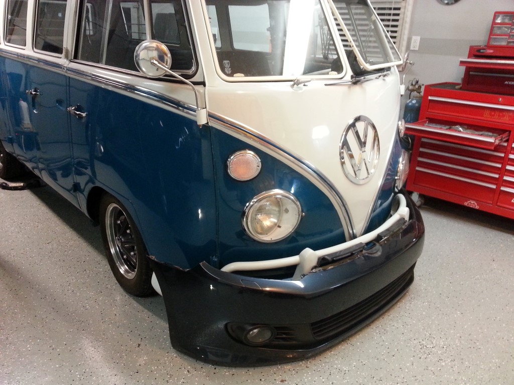
So what it boils down it is that at high RPM under load there is not enough advance due to the ruptured canister, the explosions are happening too late, which means that they’re not as effective, which means that all the explosions have to therefor be more powerful to achieve the same level of power, which means more fuel, which means more heat; and thus the overheating problem. I have a replacement vacuum canister on order which should not only solve the overheating problem but increase MPGs substantially. If you made it through all of that, here’s a picture of the bus from tonight while I was figuring all this out…

Engine Back In!!
After a very long night last night and all of today, the bus is running again. There is a very specific order of assembly, and if this order is violated the engine has to come back out to start over. Although this seems obvious, several of the key early assembly parts are not so obvious. Because of this the engine was in and out a few times.
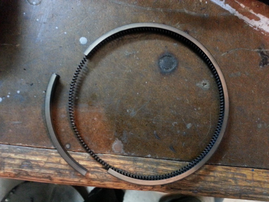
More Delays
Today I was assembling the cylinders and pistons onto the engine when a piston ring broke. Normally I would be able to go to the local auto parts place and get a replacement ring set, but since the bus had 88mm over-sized cylinders the rings cannot be sourced locally. The 88mm cylinder set is known to cause alot of problems since the cylinder wall is so thin; so I’m taking this opportunity to replace the cylinders/pistons/rings with the standard 85.5mm size. This makes the engine a ‘1600’ (1584cc) again, with the 88mm cylinders it was a ‘1700’ (1679). No changes had been made to the stock cylinder heads, so the ‘1700’ configuration would have needed racing fuel to run with any longevity. The ‘1600’ will be able to run on regular, or at-worst mid-grade.