

Crawlspace Door
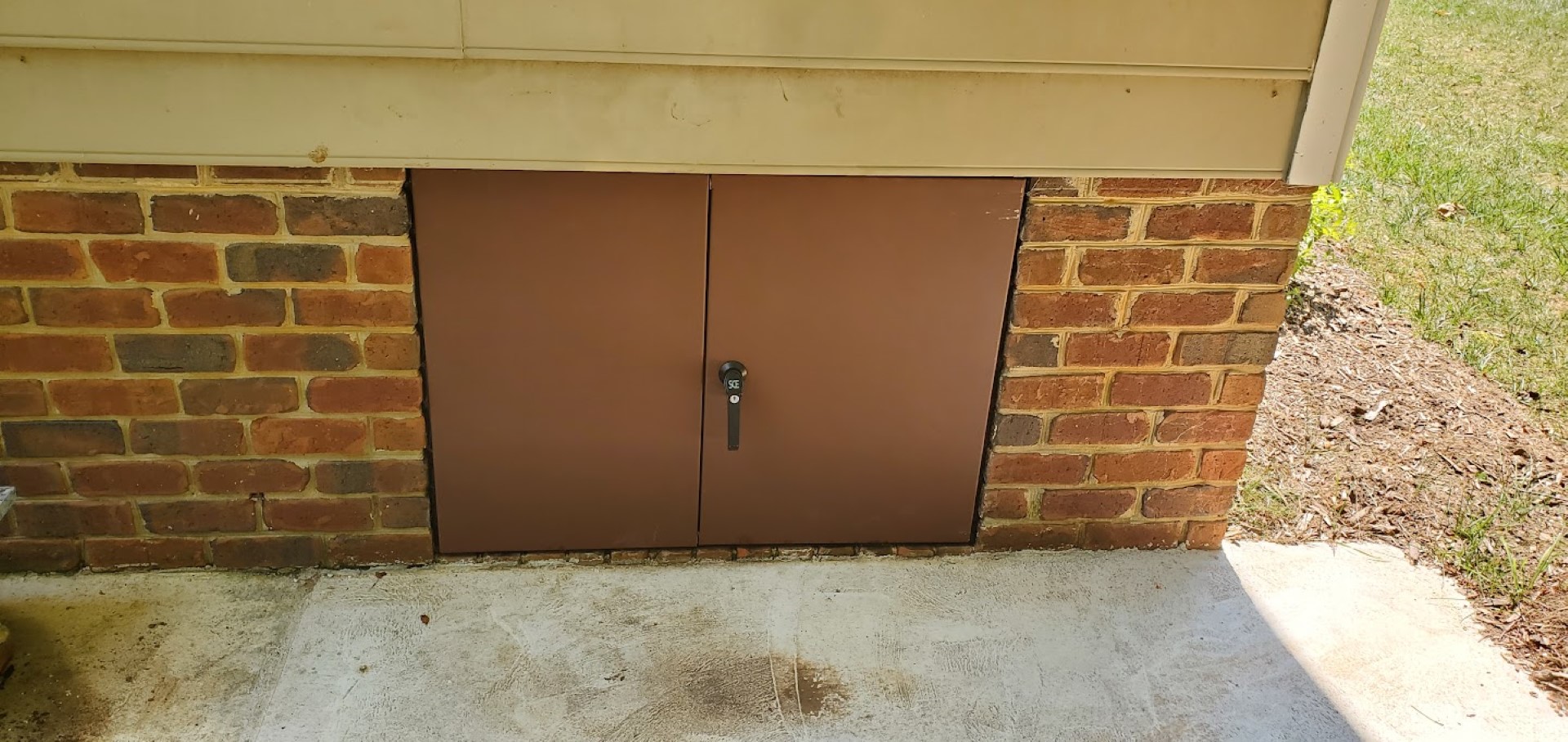
One side of the house had a site-built wooden door. This always bugged me since it’s the only place on the house where wood extended below the wall’s sill plate – everywhere else it was masonry or metal only. This door was vulnerable to rot/termites and also didn’t seal well (mouse risk), so I have been keeping an eye out for a better replacement – with the concrete/drainage being finished in the area this door is the last part of the overall project to remodel the area.
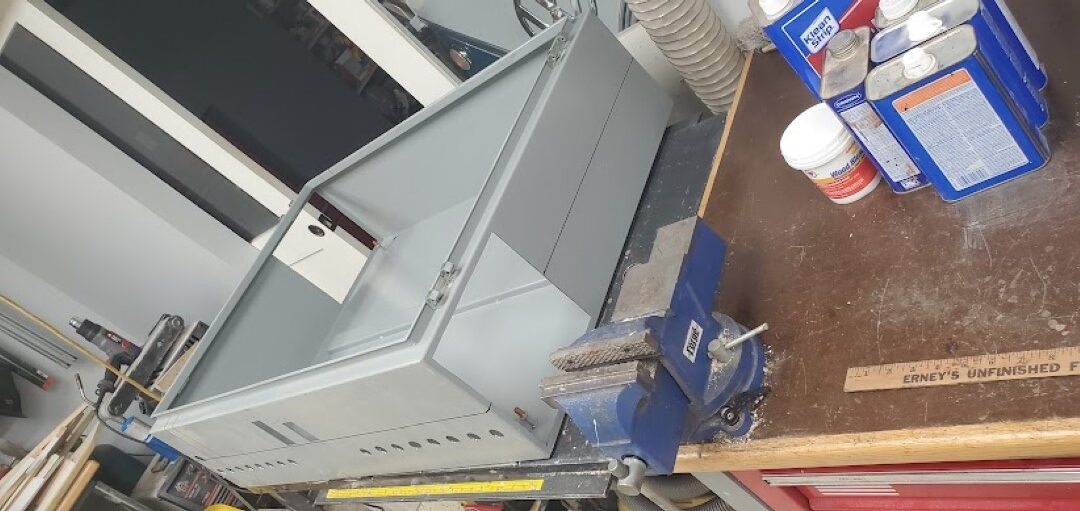
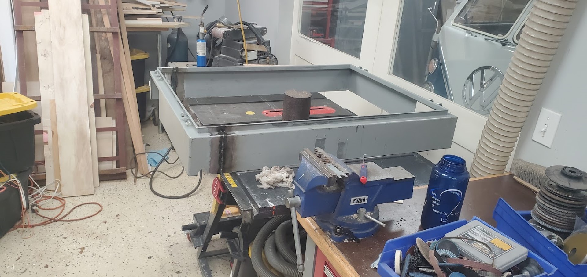
I found a used electrical control panel online that was the correct height, but slightly too wide. Since this was the closest match I had seen and since it was local I picked it up. I first cut the back out of it to the correct depth, then cut a section out of the panel and one of the doors before welding it back together. The door got some minor filler before everything was sanded and painted. The door was then caulked in place and new weatherstripping installed.
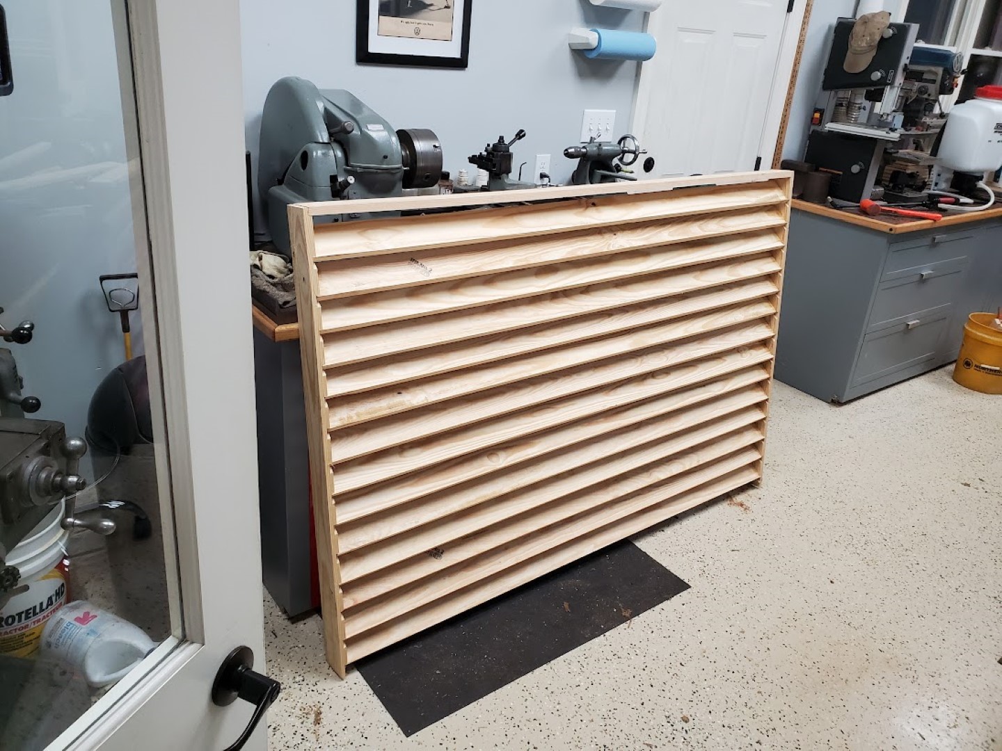
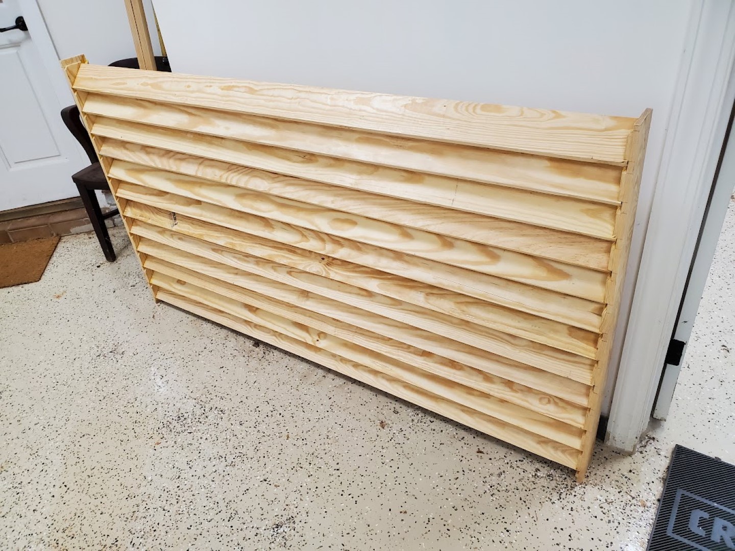
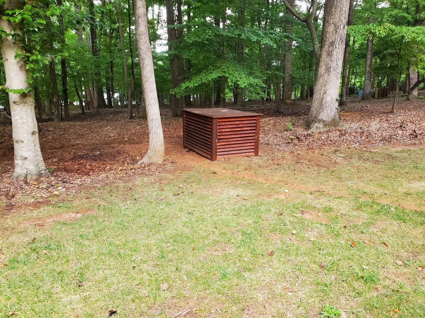
Louvered Generator Cover
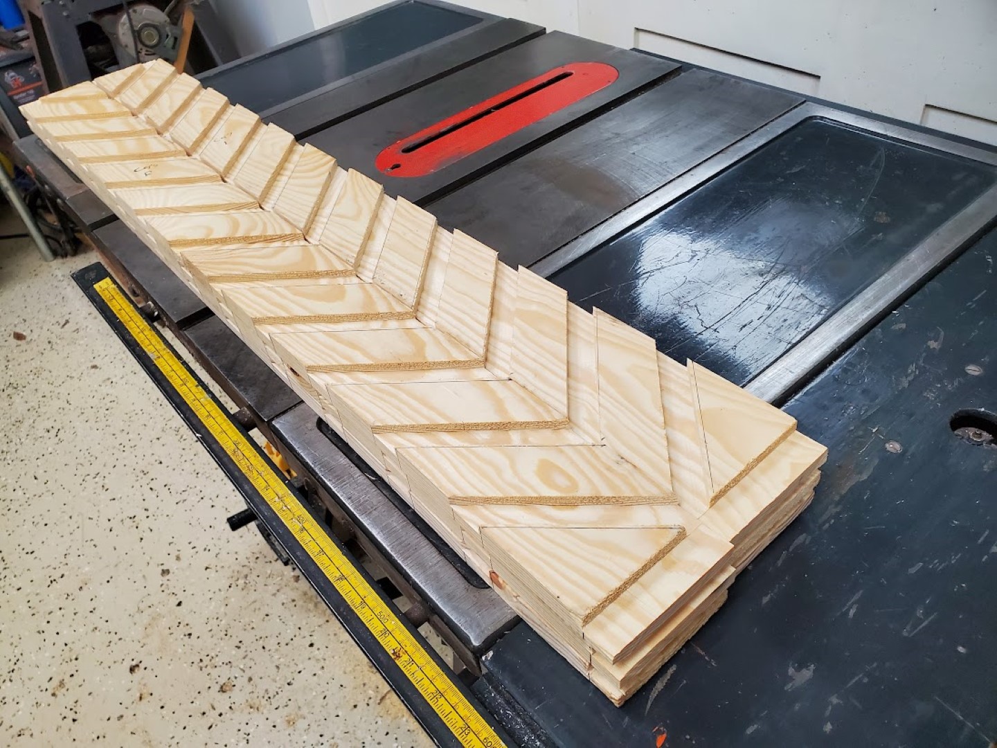
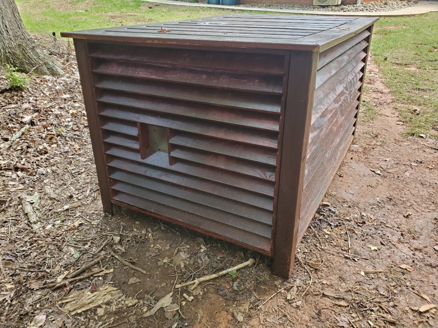
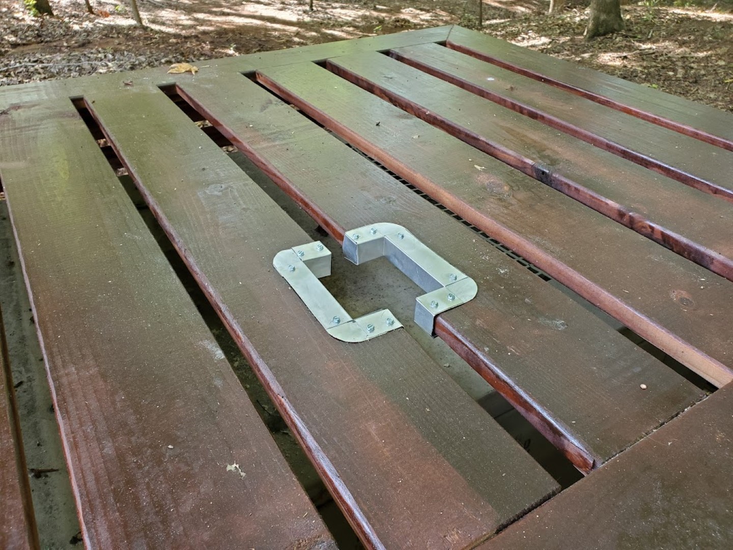
The generator is still working great but as the side of the yard it’s in has become more polished (trees/undergrowth removed, grass planted, sidewalk added, trailer moved) the generator has started to stand out more. To help it blend back in I created some louvered panels to cover it. The louver design allows for plenty of ventilation from all sides. The panels consist of 1×4 slats secured into 1×4 ends with angled grooves cut via dado stack. The panels corners are joined together at 4×4 posts. The rear panel has a cutout for refueling, the top has a cutout for the exhaust flap (with flashing for heat protection) and half of the front folds down for control panel access.
I also made a similar but much smaller cover to go over the top of the plastic service dome for our underground propane tank.
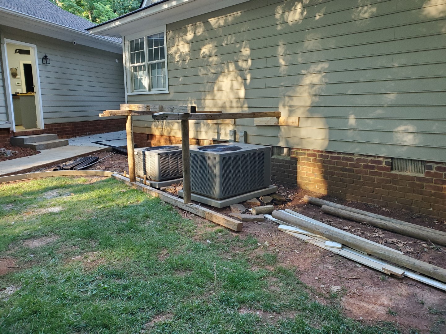
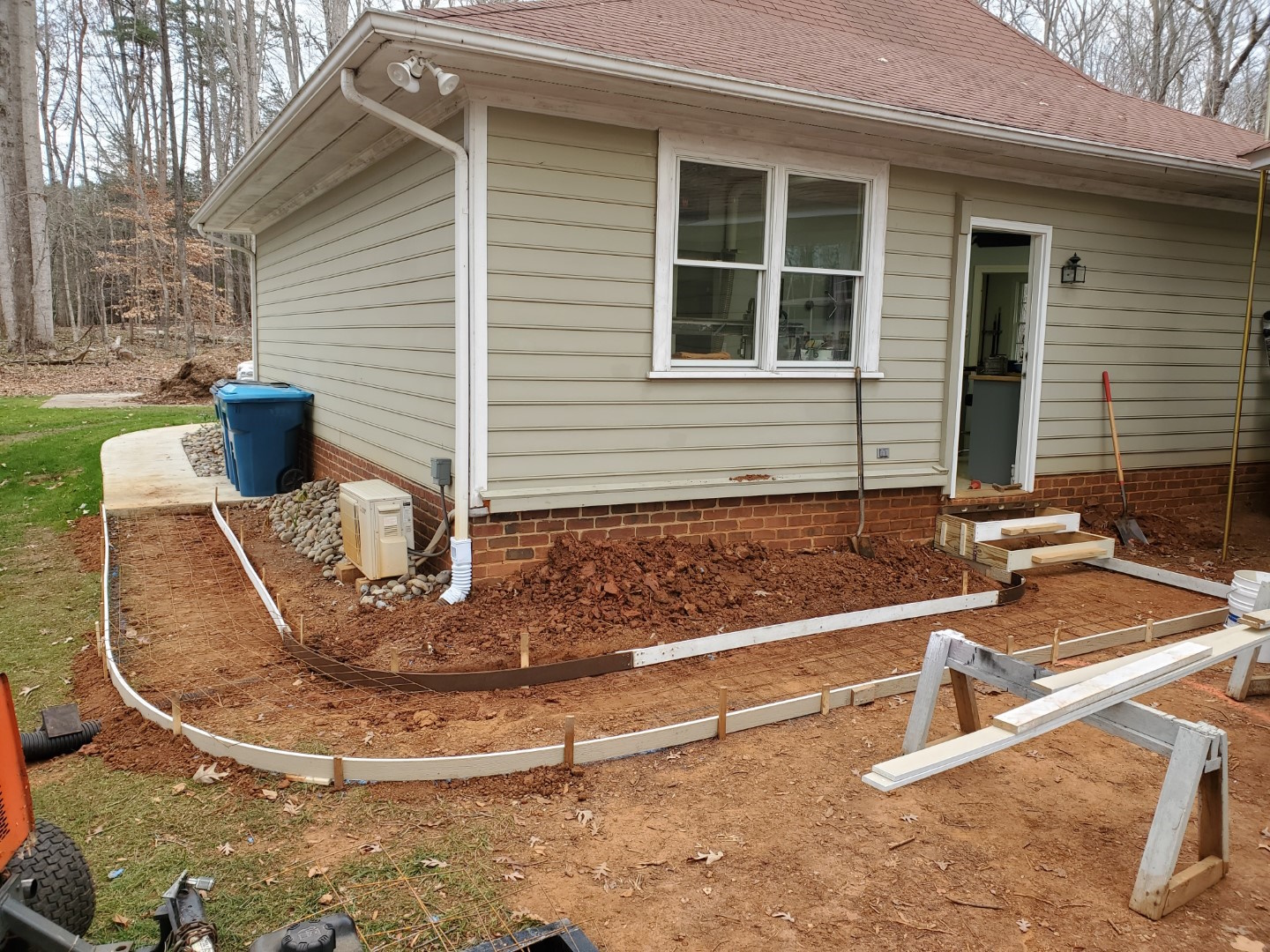
Sidewalk Project: Nearly Complete
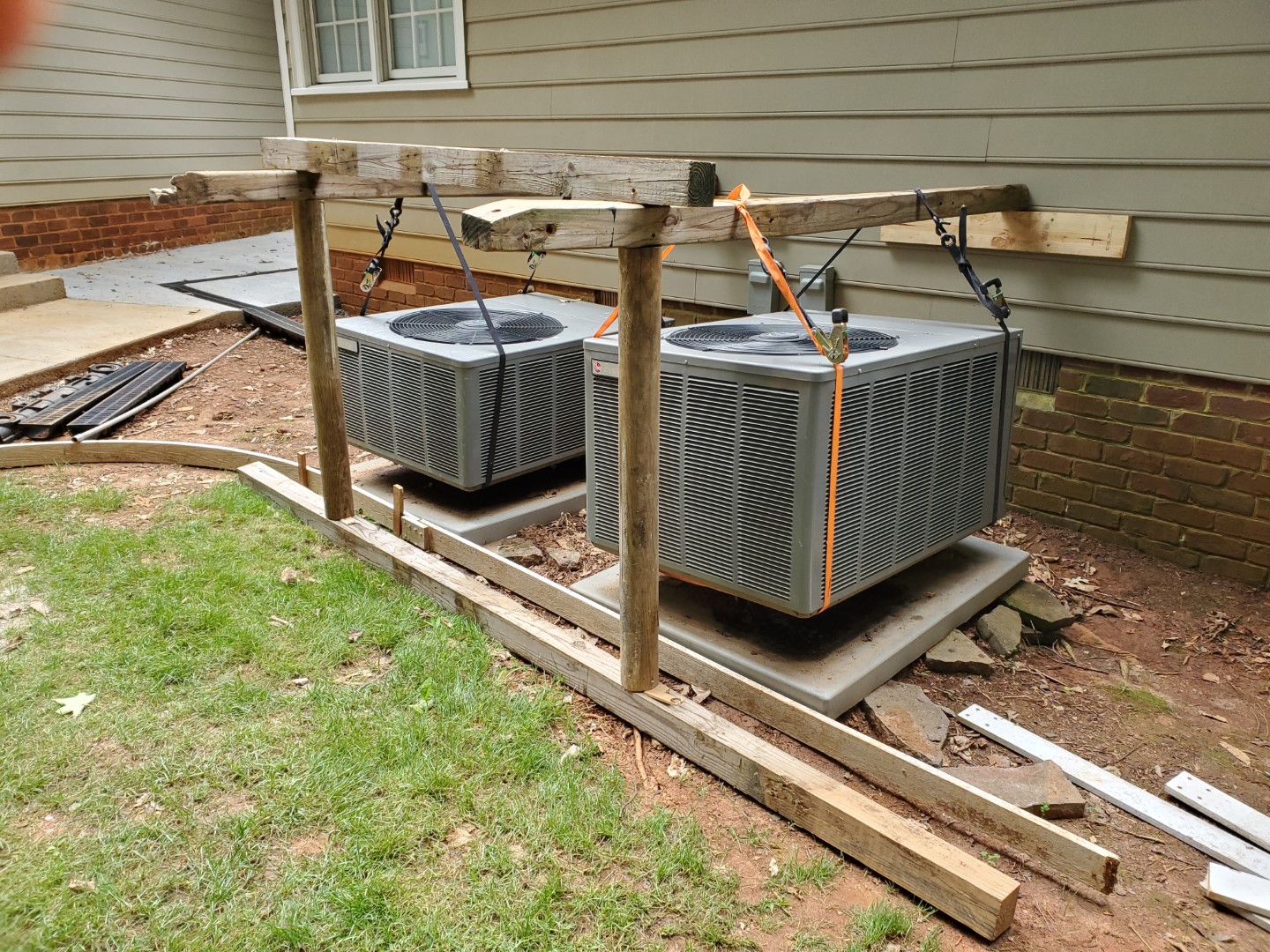
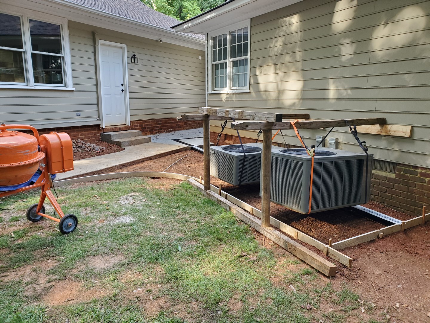
The next two phases of the garage sidewalk project have been completed. The first of these was relatively easy, just a flat section in an alcove between the house and garage. A channel drain was added at the roof drip line and conduit added for future utilities to access the area (hopefully fiber eventually). The second phase was not as simple since there were heat pump units in the way. To get around this I installed a ledger board to the wall framing then made a frame out of old landscape timbers, with the frame legs outside the concrete area. The units were then carefully lifted onto the frames with ratchet straps, making sure not to stress any of the electrical/refrigerant connections. Concrete was then poured the same as before.
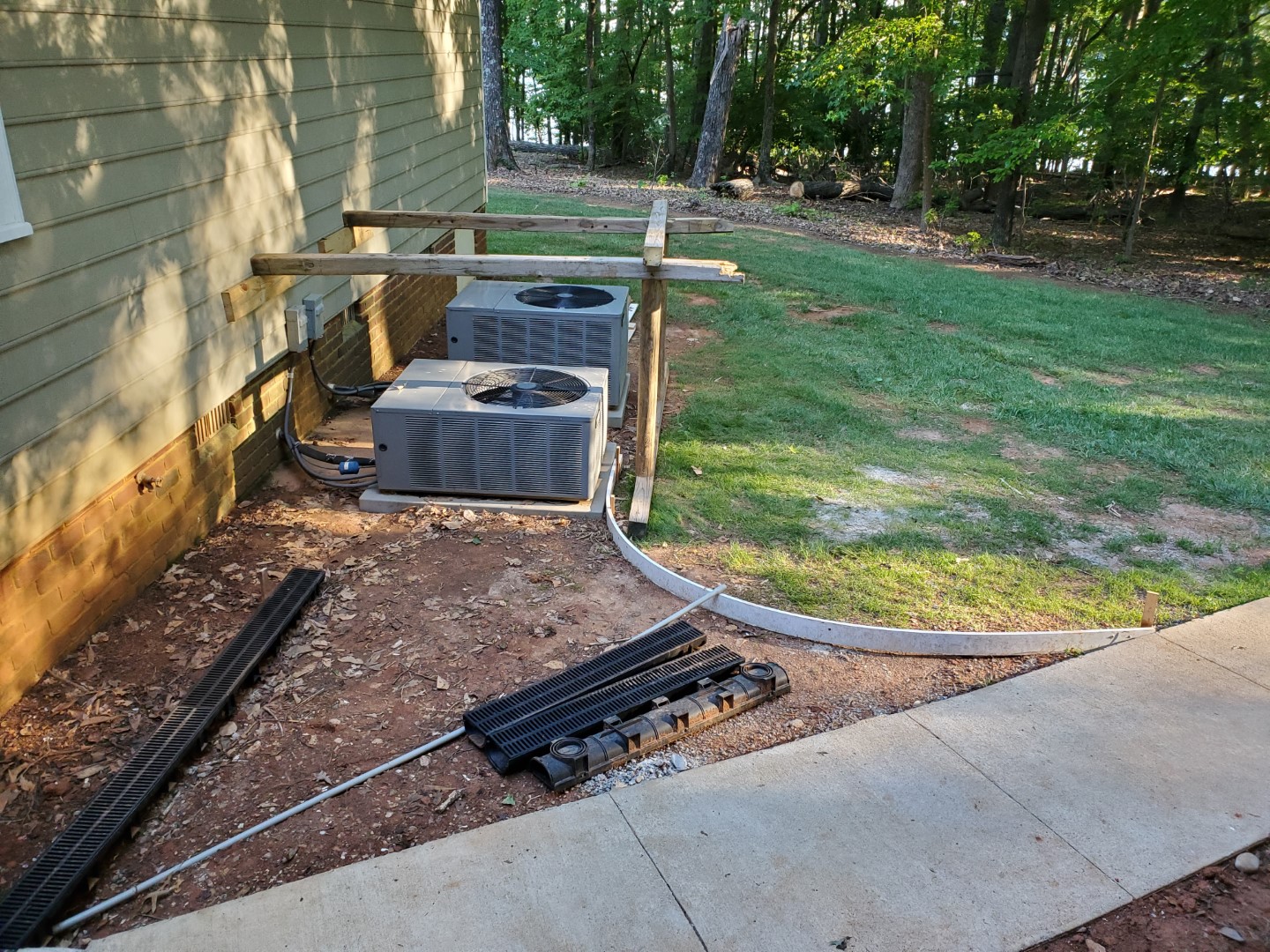
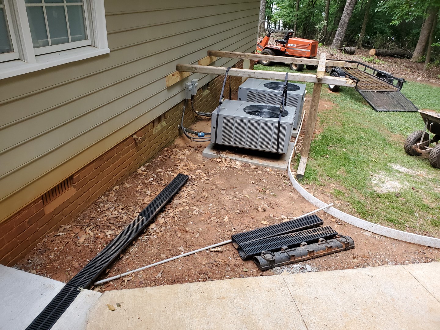
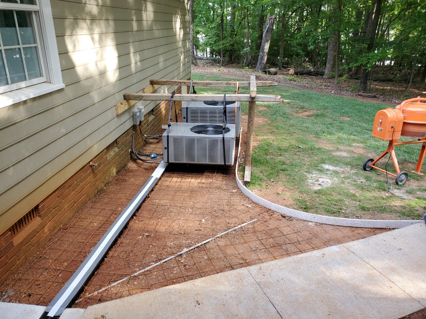
Next phase is one more small section from the heat pumps to the end of the wall, this will catch the rest of the rain run-off and direct all of it into a pipe that will run under the grass.
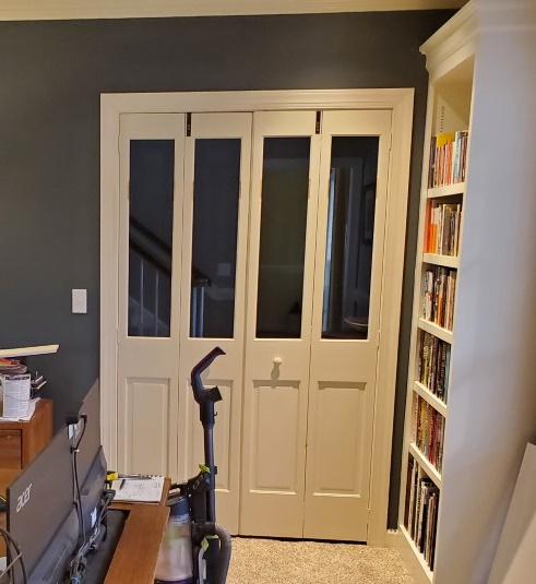
Glass Bi-fold Doors
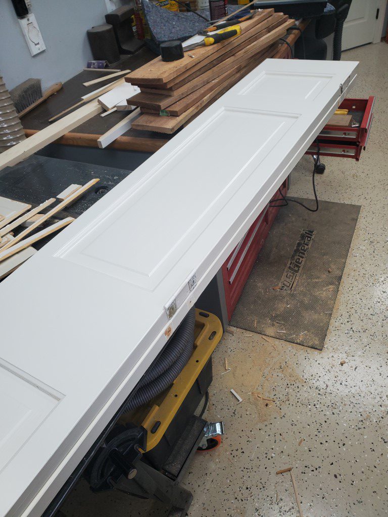
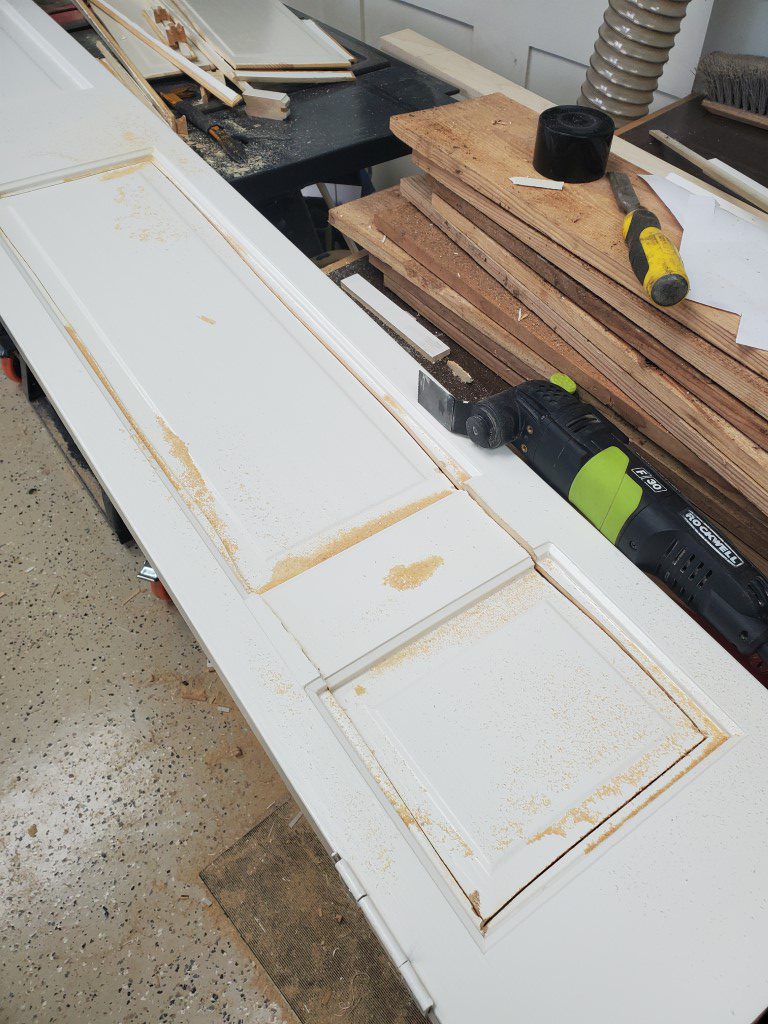
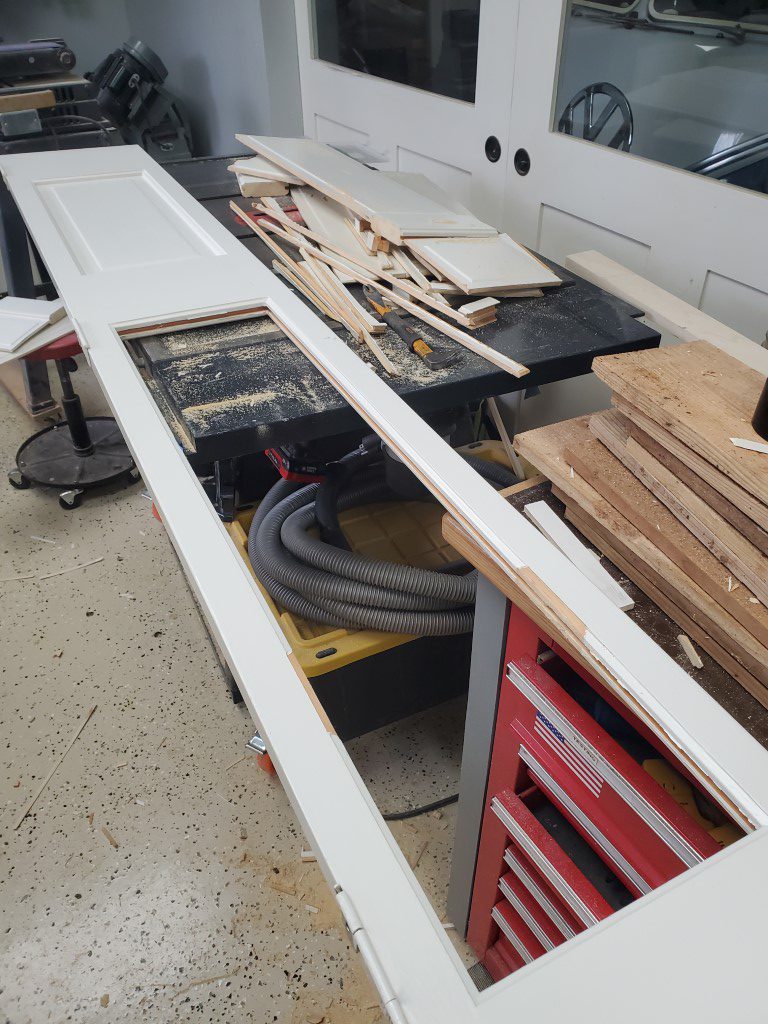
The home office has some bifold doors connecting it to the foyer. Normally I’d like to leave these doors open since it allows light & visibility to the front door, but that would also allow cats to enter the office (usually at the worst times). The solution seemed to be changing to bifold doors with glass panels, however these are very expensive. Since the existing doors were already good quality solid wood though, a good compromise seemed to be modifying them to add glass. I was able to find tempered glass for a reasonable cost online, so I went ahead with this project. Tempered glass is the key since it will break into small (less dangerous) pieces, it’s a code requirement for doors in most locations. The process went as follows:
- Cut a middle section out of the panels on each door. This allowed room for the next step.
- Pull the remnants of the panel edges out of the groove in each door frame.
- Route one side of the door frame flush with the bottom of the groove.
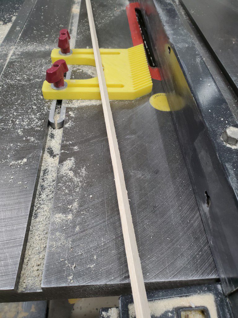
- Install glass panel.
- Make trim piece to hold glass in place, this piece basically replaces the piece of the original groove edge that was routed away.
- Carefully tack trim in place.
- Fill/Sand/prime/paint trim pieces.

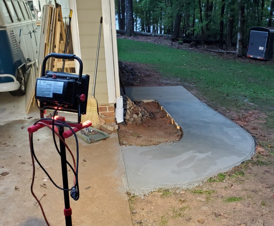
Sidewalk Sequel
The next phase of the garage sidewalk project has been completed. Same process here, but a larger section was made possible by the addition of a concrete mixer. At the same time the old railroad timber steps to the back door were replaced with concrete. Next phase will be filling in an alcove between the garage & house (along with adding a channel drain to finally catch water from that area) and then last a section under the heat pump units.
Trash Can Sidewalk
Quick project this weekend to create an area for trash/recycling can storage. I used some odd 1×4 composite trim type boards left by the previous owner for most of the forms, for the tighter inside bend I cut a few strips of 1/8″ masonite panel and glued them together in-place. I also setup a length of drainage pipe to direct the gutter downspout under the sidewalk. Wire grid was set in place, then concrete hand-mixed in a wheelbarrow and poured. A few hours later I finished with a broom finish.
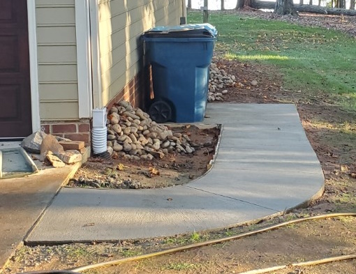
Eventually I may add a small fence/wall, but just getting the cans out of the driveway is a big improvement on its own. This yard in this area was holding a pile of landscaping rock until recently, now that it’s been moved the area will be planted with grass.
The sidewalk will eventually be extended around the garage, I’ll likely get a small cement mixer to make the process go faster – mixing a pour this size by hand it becomes difficult to mix and place the concrete fast enough that the beginning isn’t curing differently than the end, which makes finishing tricky.
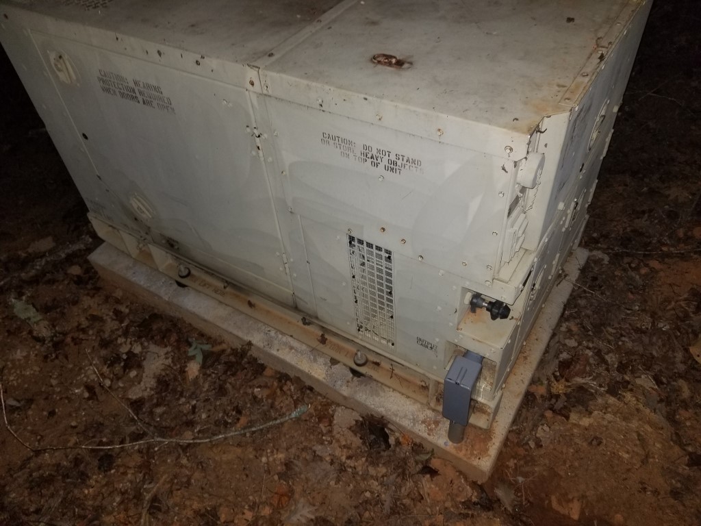
Generator Install
After fixing the generator last year (this project) I needed to install it permanently. I pulled the permit last year and it expires soon, so lately I’ve put more work into this to get it done. After a year of on-and-off work it’s finally ready for inspection. Permanent installation consists of 3 main parts: mounting the generator, installing an interlock, and running cable from the generator to the house electrical panel.
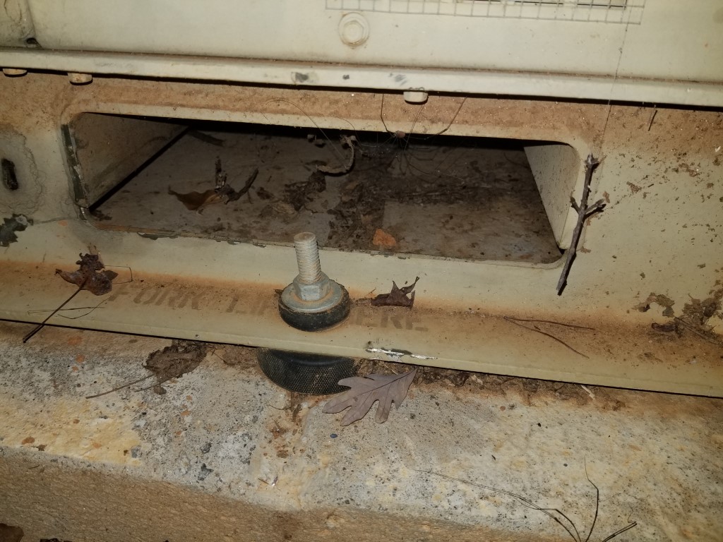
#1 – Mounting the generator was relatively easy – I dug out a flat area, made a form, added rebar, and poured concrete. The only tricky part here was keeping the threaded bolts positioned correctly so that they’d line up with the generator mounting holes. After the concrete cured I moved the generator in place and bolted it down, using hockey pucks as vibration dampers. I turned down the upper hockey pucks on the lathe and machined a step into them so that it keeps the generator centered on the mounting bolts.

#2 – The interlock requirement is the most important part of any generator installation since it prevents energy from the generator back-feeding into the utility, which would create a dangerous situation for the linemen that are working to restore power. There are several ways to accomplish the interlock:
– Automatic Transfer Switch: This switch is placed inline between the meter and main panel, during an outage it automatically disconnects the house from the utility, connects to the generator, and sends a signal to start the generator. This capability would be nice but there’s a lot of complexity, expense, and extra work involved.
– Manual Transfer Switch: This switch is placed inline between the meter and main panel and you can manually select which power source the house is using. This is much simpler than the automatic switch, but still requires an additional small panel for the switch.
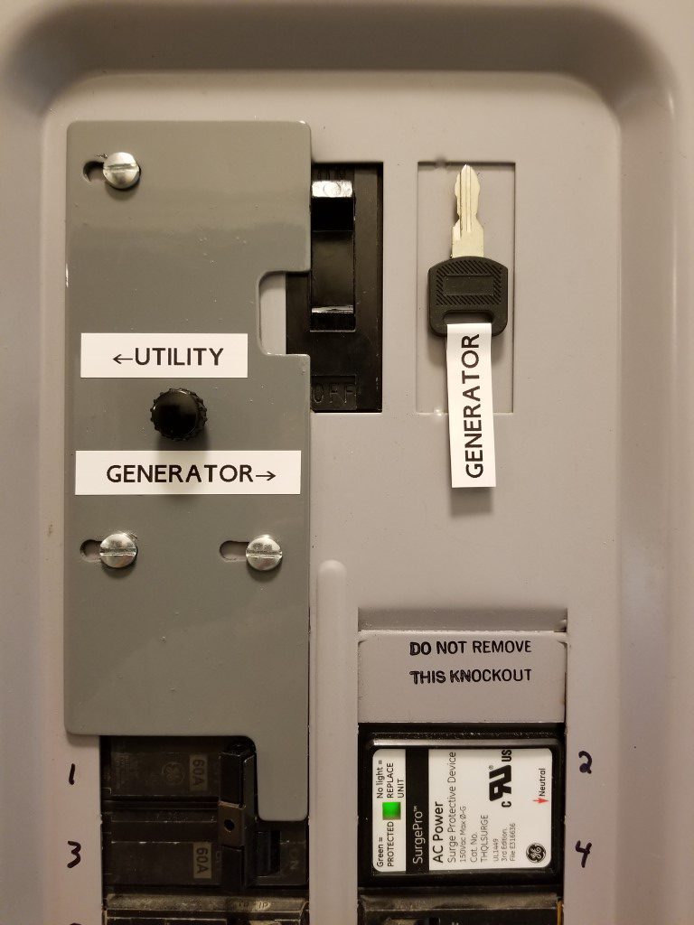
– Main Breaker Interlock: This is a sliding plate that mounts inside the existing main panel and it prevents the main breaker from being ON at the same time as another nearby breaker (and vice versa). The generator powers the main panel through the nearby breaker.
I opted for the Main Breaker Interlock since it’s allowed where I live and it’s the simplest way.
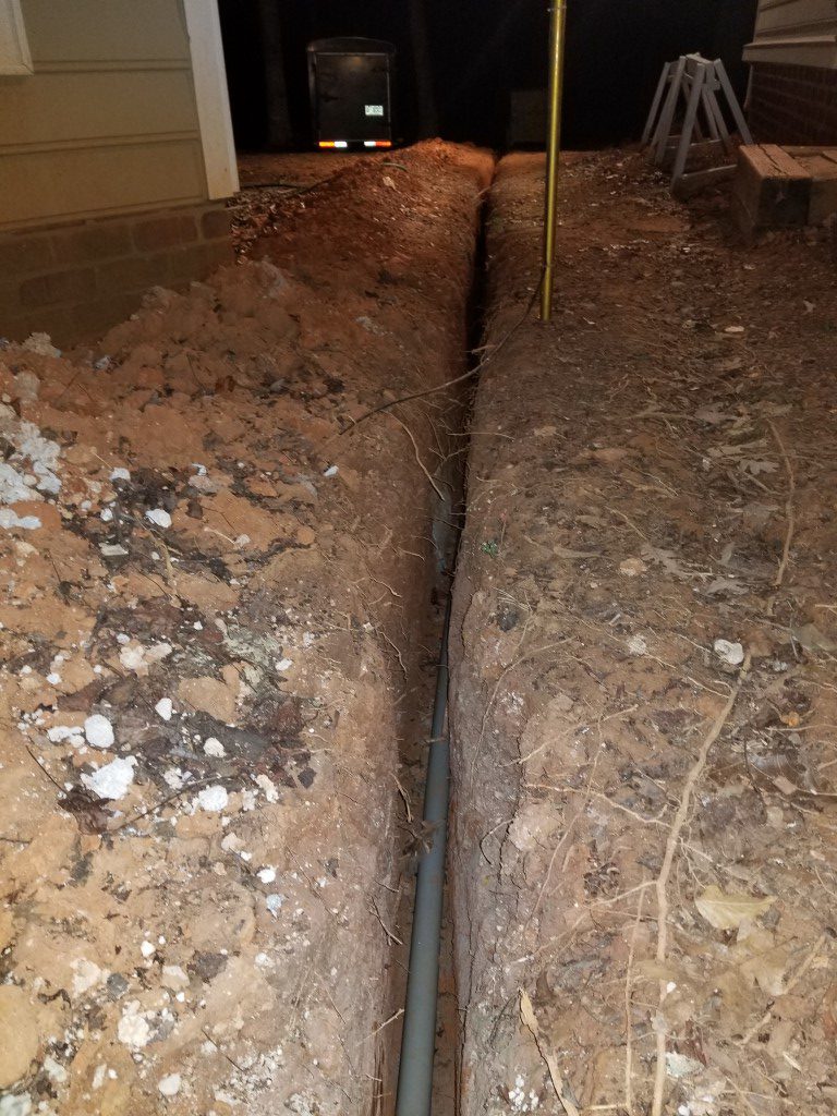
#3 – Running cable was the toughest part. Since the generator isn’t a residential unit that’s fire-rated to be directly next to the house (it probably would perform better than a residential unit, but the military doesn’t do the residential testing) it had to be at least 2ft away. 2ft away would have made for an awkward placement and it would have been in the way a lot, so instead I took it much farther out near the tree-line; leading to a ~60ft long trench. Code requires either 18″ of cover or 24″ of cover depending upon whether or not conduit is used. I opted to use conduit since the shallower trench saved digging effort and also reduced the chance of encountering any other utilities in the process. Most of the digging was through very dense/hard clay and it was slow-going with a trenching shovel. I welded the shovel back together at least a few times. I also experimented digging with the pressure washer, which mostly made a mess. The last 2ft near the house were through concrete; the technique I used for this was to turn the area into Swiss cheese with a hammer drill, break it out with a small air chisel, and then progress down to the next layer. I had been on and off of this effort over the past year and finally finished this weekend.
(#4) Misc things. Since the generator wasn’t originally intended for residential installation there were a few extra things I did to convert it:
– I added cabinet locks to all of the access doors. This isn’t for security so much as it is to prevent anyone that shouldn’t be in there from getting into danger, especially the front door that has the output terminals directly behind it.

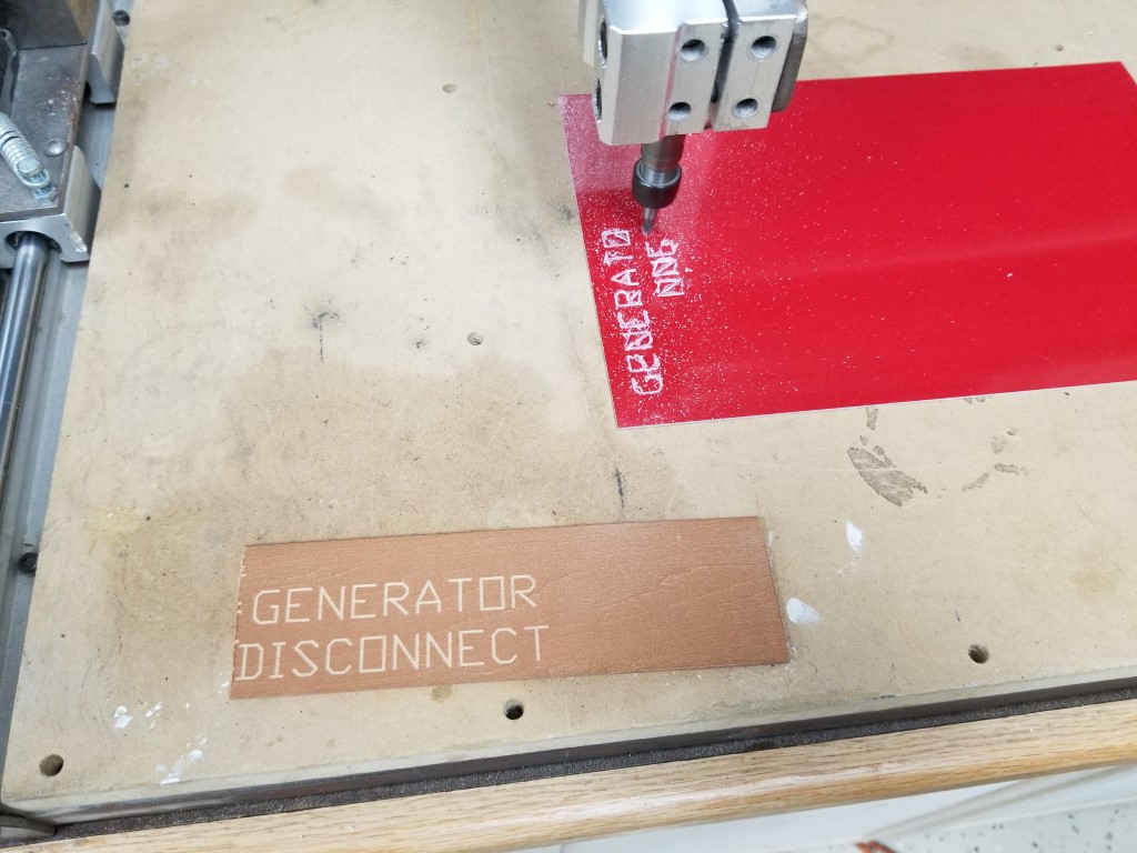
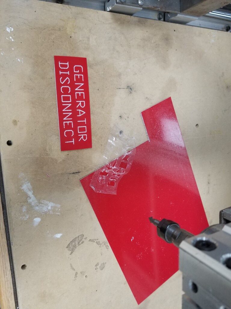
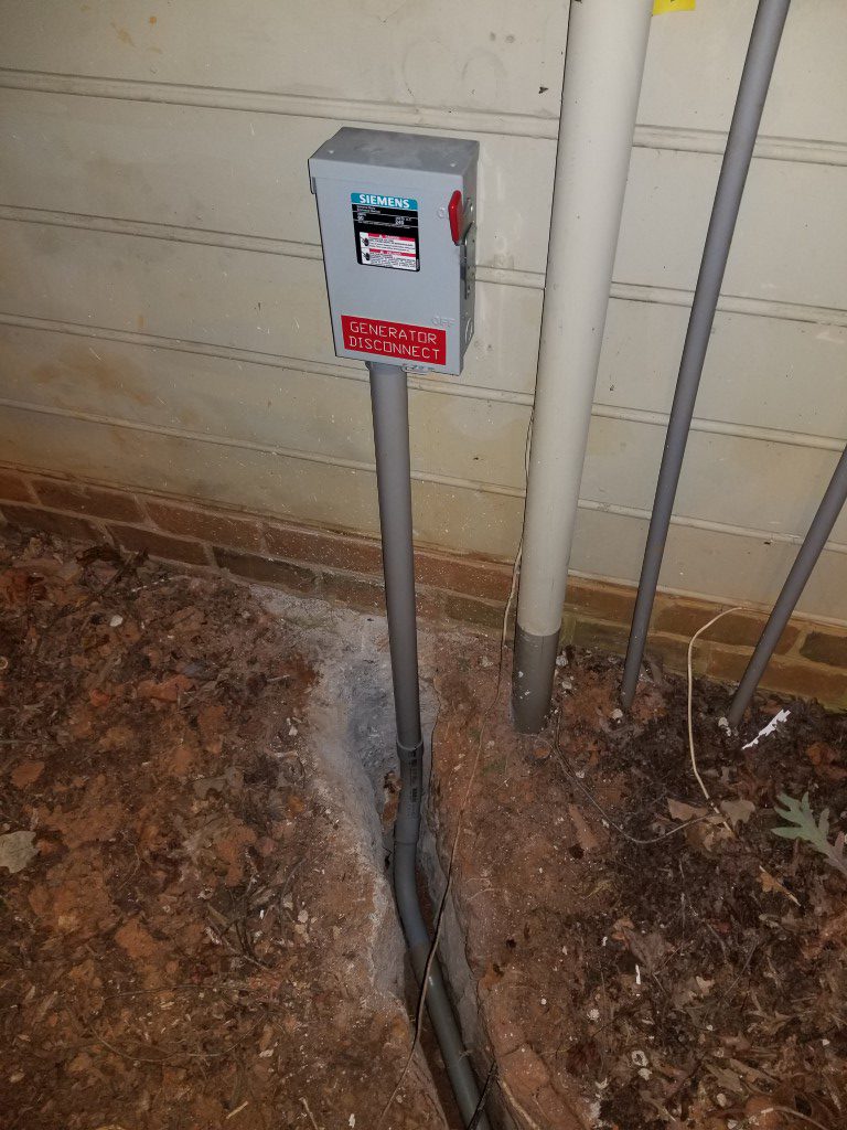
– One of the code requirements is that there must be a way to disconnect the generator outdoors. The generator itself sort-of/kind-of meets this requirement since it has a switch on the operator panel that will open the relay that connects the output power. Since this switch isn’t directly a disconnect though and since there’s a lock on the operator panel that could restrict access I also added a ‘real’ disconnect on the exterior of the house. I used the CNC router to make an engraved sign to mark it.
– Since the interlock completely disconnects the house from the utility it can be tough to know when power is restored. Electrically it would be possible to have a light/buzzer on the utility connections before the main, but since this wouldn’t have a breaker it wouldn’t be safe or code compliant. I found a device that’s made exactly for this problem and installed it. It has it’s own power via a 9V battery and has an antenna that wraps around the line from the utility to monitor power status. The alarm is armed manually when on generator power and as soon as utility power returns its siren sounds.
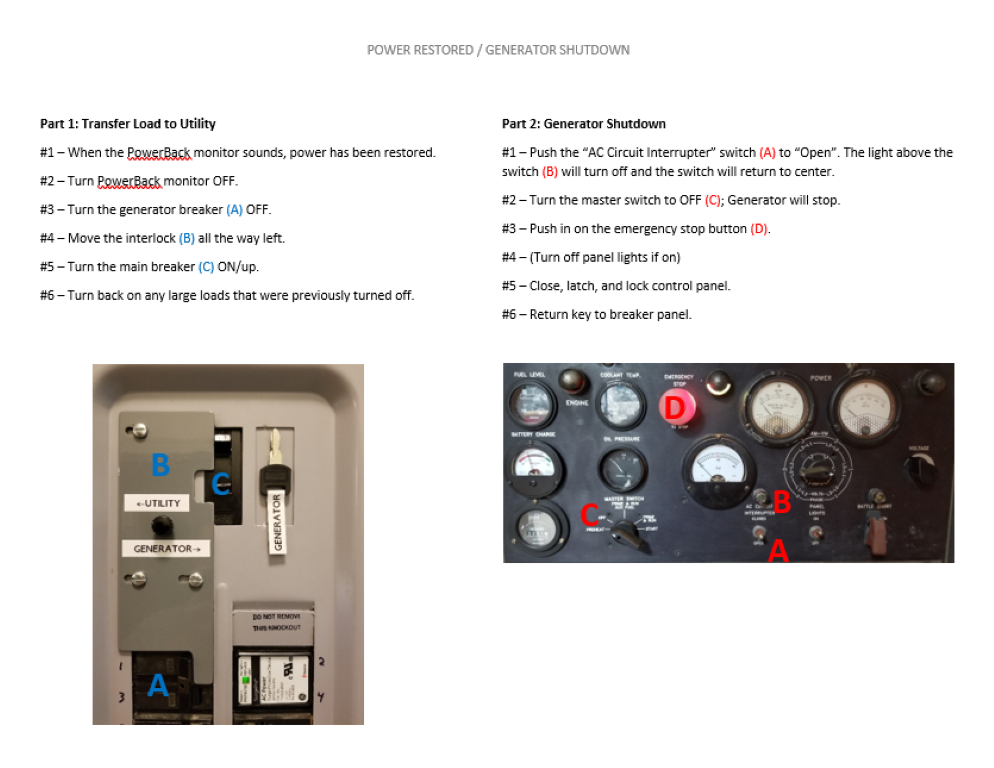
– I made a step-by-step instruction list with photos so anyone that’s home at the time of a power outage can start the generator and operate the interlock. This list and the key to the generator are held inside the main panel with magnets.

Next step is to get it inspected and then I can backfill the trench and clean the mud off of everything one last time.
Exterior Projects & ‘Custom’ Molding
This weekend I finally got around to a few exterior projects at the house:
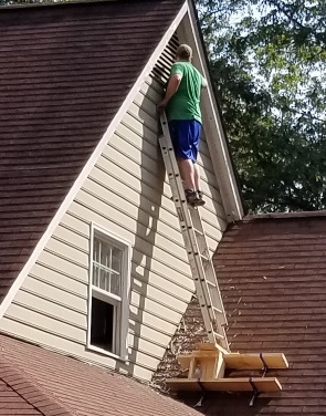
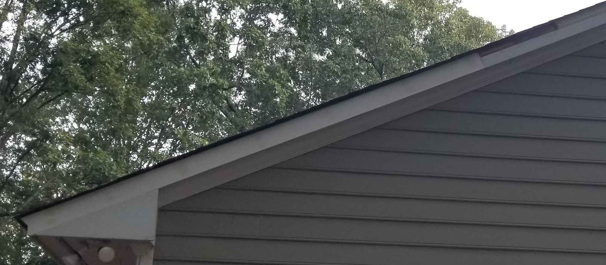
– One of the gable sides had flaking trim paint on its vent / rake boards and needed fresh paint on the siding. I sanded and repainted the trim and then put several coats of new paint on the siding. This gable end is the only original Masonite siding on the house that’s exposed (the entire back was replaced with LP Smartside by the previous owner, the dormer siding I’ll be replacing soon, and the rest of it is either under the porch or deep eaves where it never gets wet). Anywhere Masonite siding can get wet it’s critically important to keep good paint on it to avoid swelling; I think I caught this just in time. Getting access to the area took a little creativity and involved a few roof brackets, planks, and making a platform/box from 2×10’s; it was very rigid once all the parts were secured together though.
– Installed gutter guards. Leaves should start falling soon and I’ll see how it goes, anything will be an improvement.
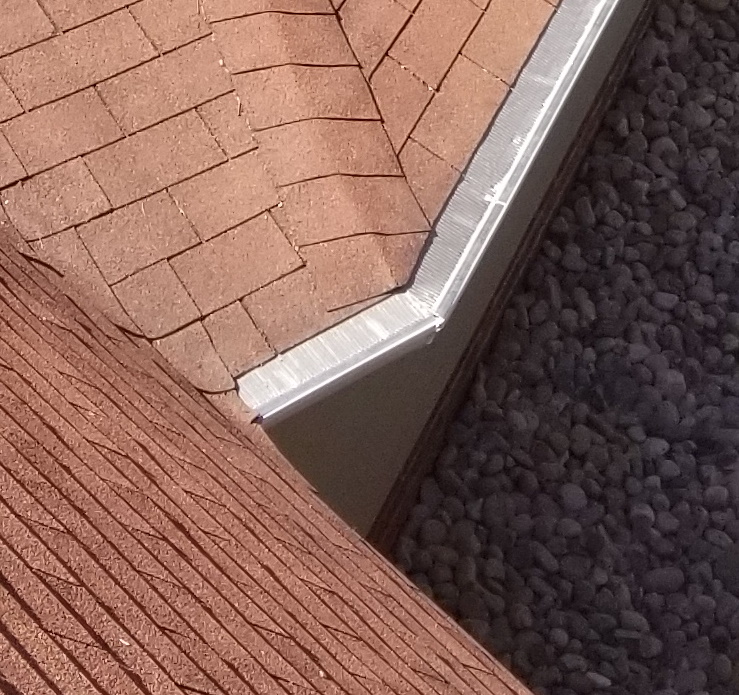
– The gable side on the back of the house had a rotted rake board and molding. Replacing the rake board was no problem; I just needed to rip a 1×6 to the exact width and put a slight roundover on the bottom edges to match the existing rake boards.
(I didn’t get a before shot, but this shows the new board and missing molding. The dark area of the old board was covered by bad molding, but is still good. It will get primed before installing the molding, and this way the seams are staggered for stability)
Unfortunately the molding that’s between the rake board and shingles (conveniently called ‘shingle molding’) is not readily available. Replacing the molding leaves several options:
#1 – A millwork shop may have it in stock, but this would take a lot of driving around to find. Usually those places have 8-5 M-F hours and sometimes won’t talk about such a small order.
#2 – I could probably find it online, but it wouldn’t ship in one piece plus there would be a delay time, added shipping costs, etc.
#3 – Sometimes it’s possible to find the same profile on a larger piece (i.e. base molding) and rip it to width. I checked this as an option when looking for for the molding originally, but this also wasn’t available.
#4 – If I found the correct profile router bit I could make the molding with the router table. This can be pricy though, plus it adds delay time and it takes a lot of setup/finishing to get a good output.
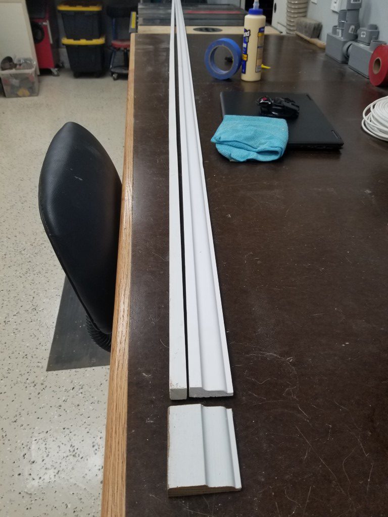
#5 – I was able to find a matching profile on a piece that was too narrow. Since the ‘missing’ part is rectangular it’s possible to just make the missing strip and glue it on.
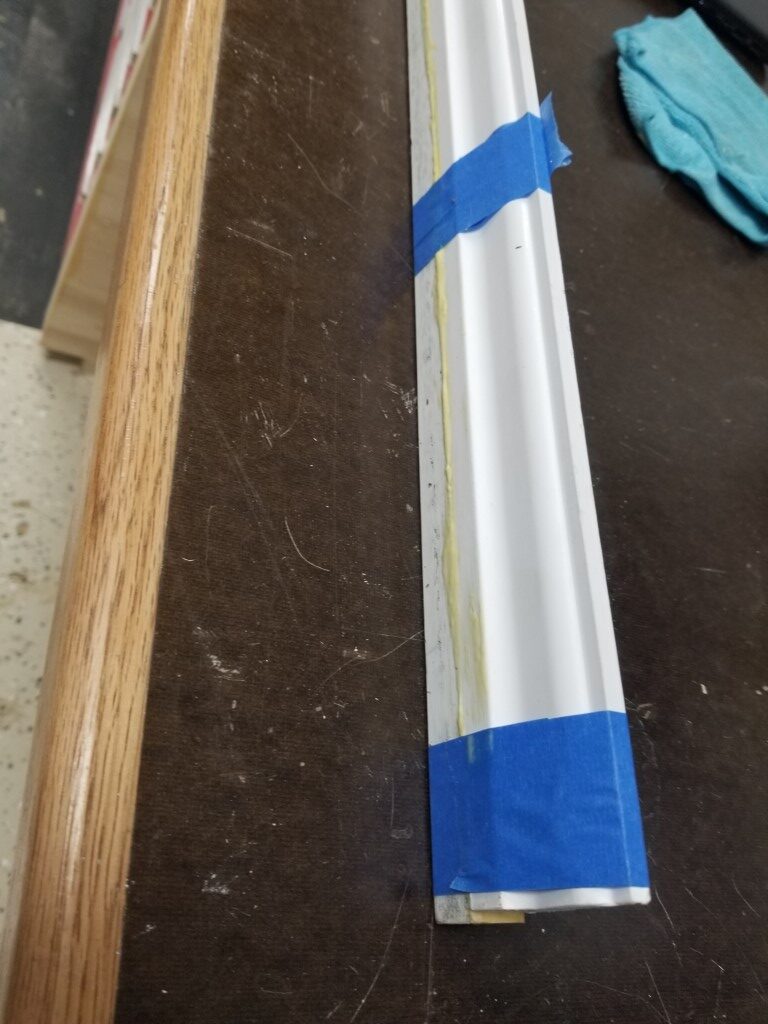
I’ve used #4 for matching other weird trim on the house, but for this scenario #5 made the most sense. To get a good glue joint I first ripped a bit off of the pre-primed molding to expose the wood. Next I ripped a 12ft scrap of 1x{something} to the right width. Dry fitting the two pieces next to each other showed that the 1x piece was just a bit thicker than the molding. I feed this strip through the planer until it was an exact match and then tightly taped the back sides of the two pieces together, forming a hinge. The tape ‘hinge’ was opened to apply glue and then tightly taped back together. Once the glue dries overnight it will be scrapped, fed through the planer, and then sanded, primed, and installed.
Saw Milling Test
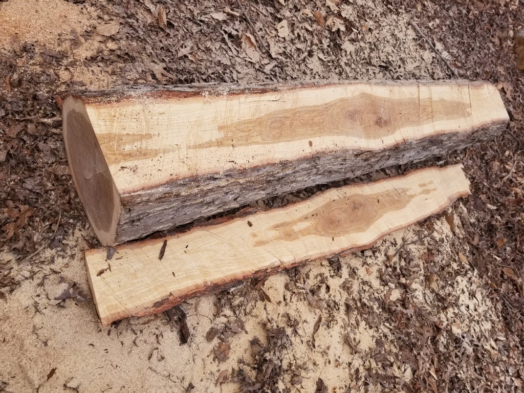
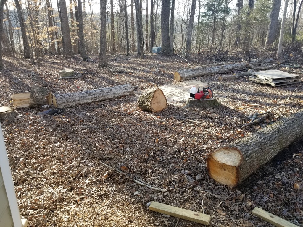
Last fall prior to Hurricane Florence I took down some good-sized white and red oaks. These were great trees but both had large limbs overhanging/threatening the garage, so they had to go. Rather than cut them up for firewood as usual I let them stay where they fell through the winter. Today was unseasonably warm and I took a stab at milling one of the logs. Drying takes a long time, so the point of this was to get at least something started – this way if I don’t finish milling the rest of it for a while I’ll at least have something in the queue.
To make the milling cuts I just free-handed with the chainsaw and there’s a good bit of variance in thickness as a result; to get straight boards I’ll have to deal with this variation at the joining/planing stage. For the next attempt I plan to build a metal guide frame over the saw to allow it to rest level on top of either a ladder laid on the log (first cut) or the level surface made by previous cuts. Also, my saw is a middle/low power model (3HP) and bogged down occasionally. Normal chainsaw chain is meant for cross-cutting and takes too big of a bite for ripping, for the next attempt I plan to modify an old chain into a ripping chain by grinding back some of the teeth – these converted teeth will help clear chips out of the cut rather then cutting themselves and it should mean less bogging down.
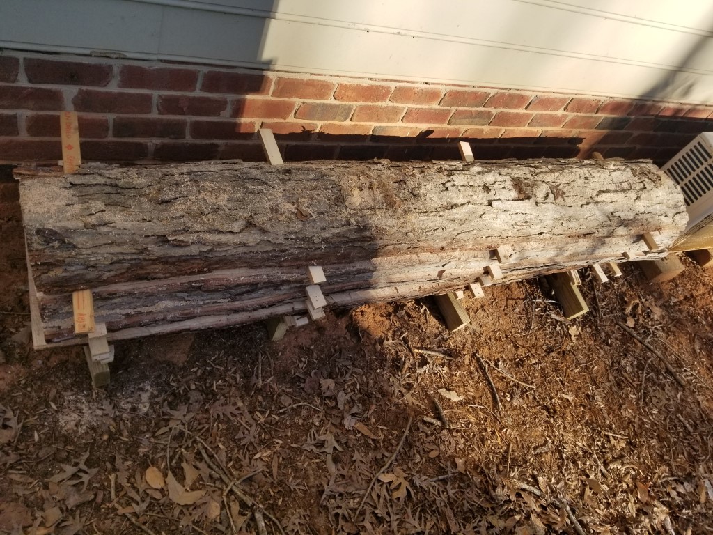
Once milled, the log was reassembled with some ‘sticker’ pieces I cut from scrap 2×4’s to create airflow gaps. It’s under an overhang that should provide enough rain protection. The drying happens from the inside out over a long period of time, getting wet from rain only temporarily increases the moisture level on the outside; this dissipates quickly and doesn’t hurt the overall dry time. Drying should take about a year per inch, the slabs are about an inch and a half on average so I may be able to use these as soon as next summer.
We have some ideas for the wood but no immediate plans; this is just a long-term thinking/prep. The white oak is good outdoors and may become some much-needed patio furniture. The red oak may be used to upgrade the fireplace mantel and be used for a headboard and side tables.


Dust Collection
This weekend I installed the shop dust collection system. The system consists of several parts:
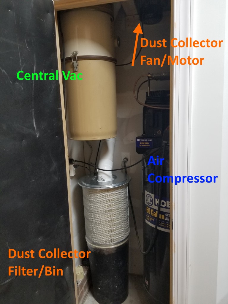
Fan/Motor: I repurposed a portable dust collector fan I’ve had for a while that’s been underutilized (collecting dust, but not as intended). Space is limited in the mechanical room so since the fan won’t need easy access I mounted it high up above the air compressor near where the dust collector pipe enters the mechanical room.
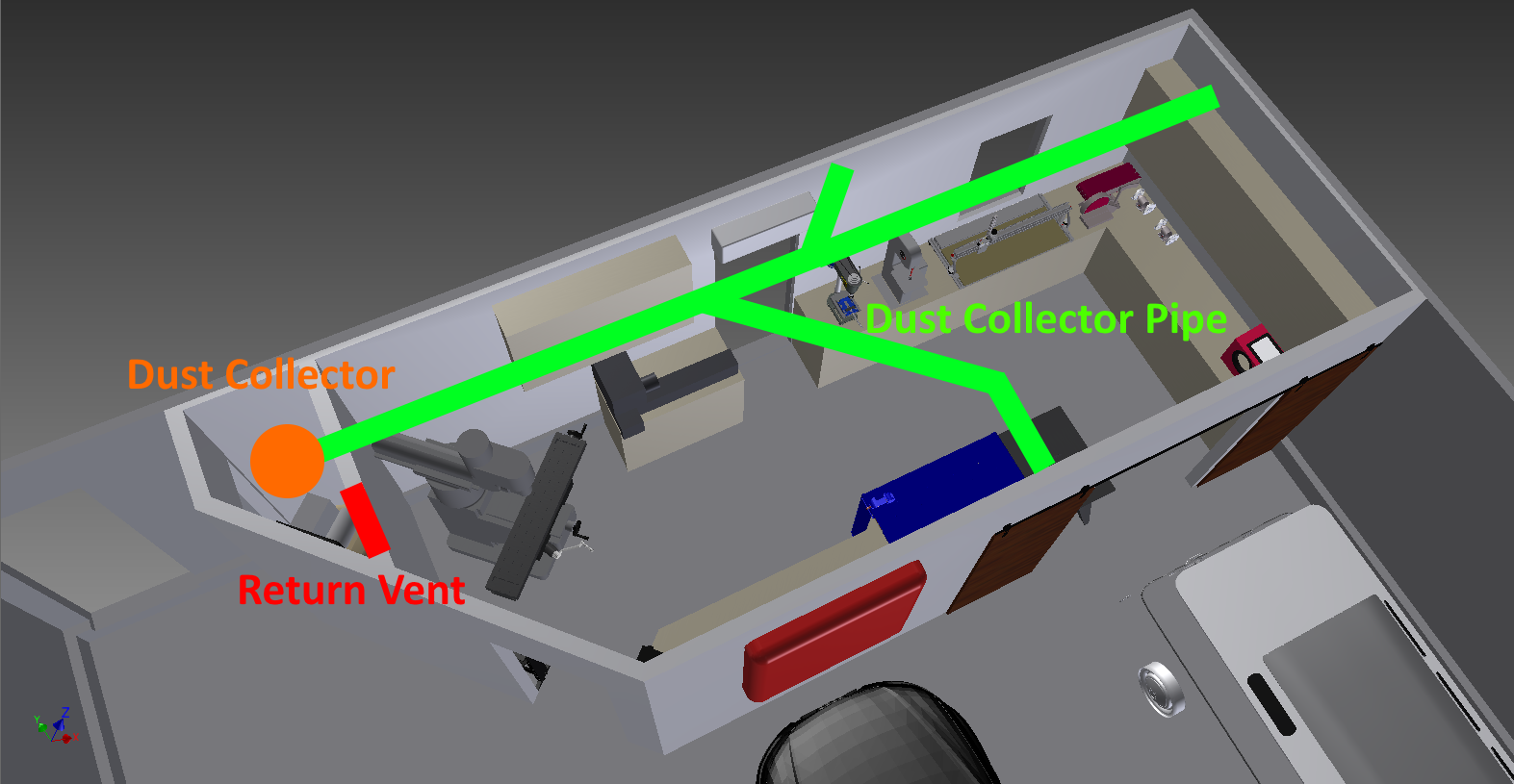
Pipes: 4″ PVC DWV pipes; there are a few branches leading to the different tools. I tried to keep the overall length as short as possible and the bend radius’s large.
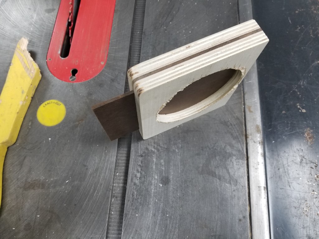
Blast Gates: The blast gates control the air flow though the system by blocking off unused branches. I made these with 1/2″ plywood and 1/4″ hardboard. Circle cutouts were made on the lathe to match the pipe outside diameter exactly.
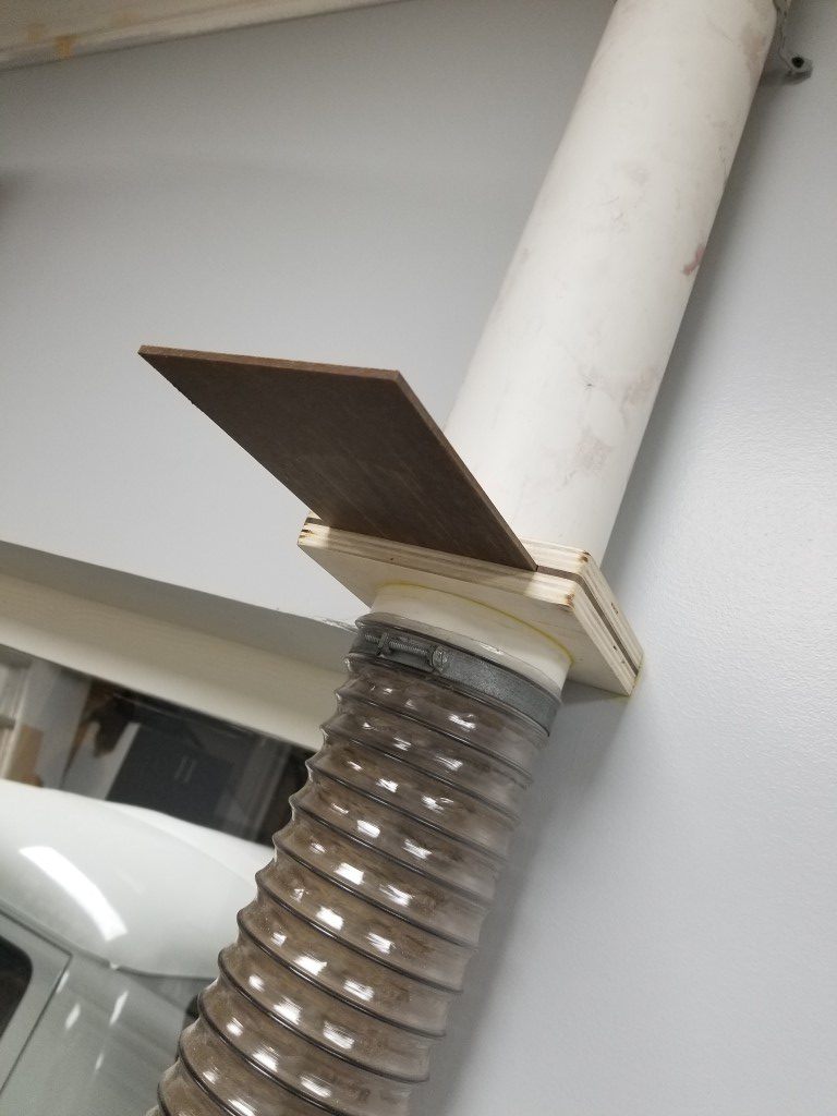

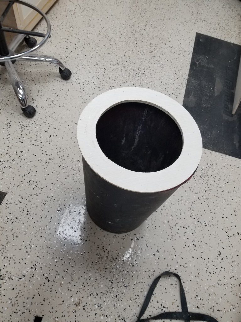
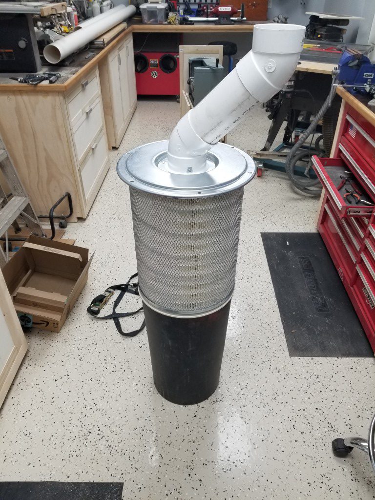
Filter and Collection Bin: The portable dust collector came with a light canvas bag that restricted the air flow massively while still allowing fine particles to escape. To improve this I replaced the bag with a semi truck air filter mounted to a trash can. The theory is that air will exit the filter and larger dust/chips should fall into the trash can below. There are purpose-built dust collection filters available, but the costs are much higher for these and the semi truck filter has the same specs; different economies of scale. To mount the filter to the bin I made a plywood ring, for now they’re just taped together but I may add latches at some point. The design may need some tweaking; I’ll know more after it gets further use, but for now the airflow is excellent.
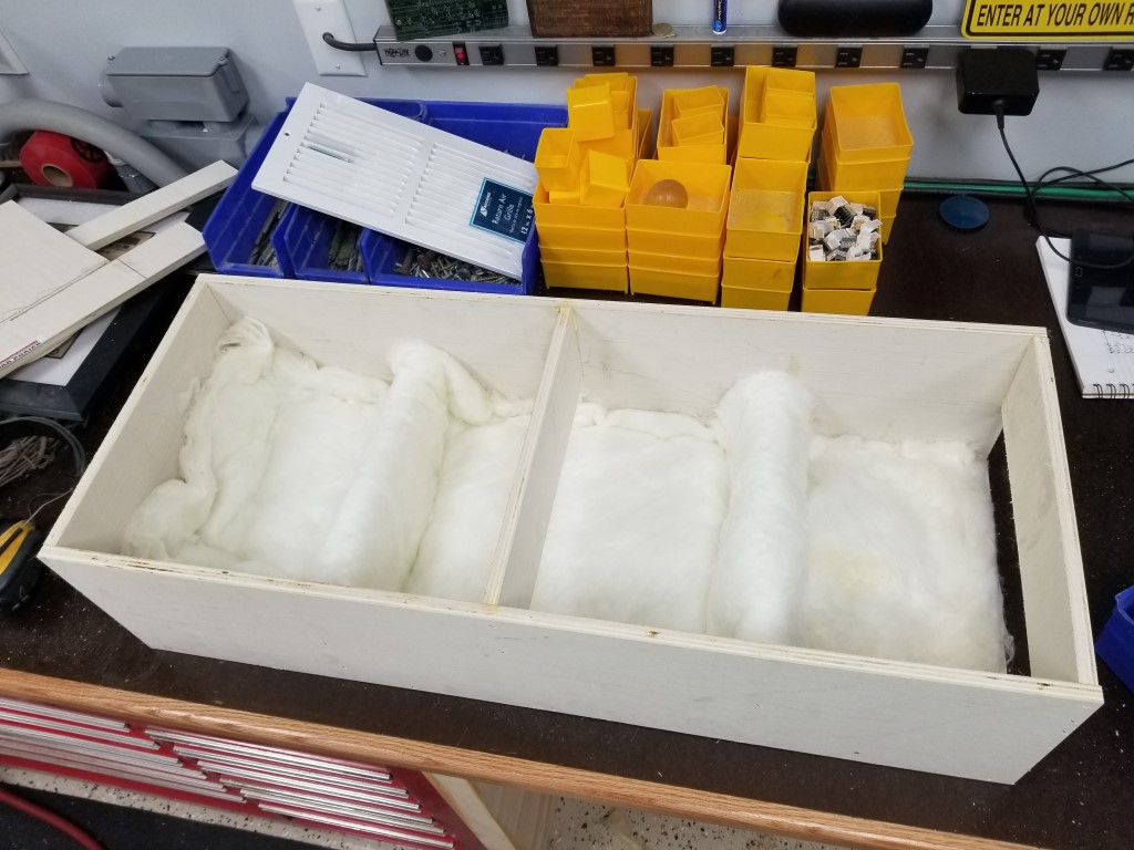
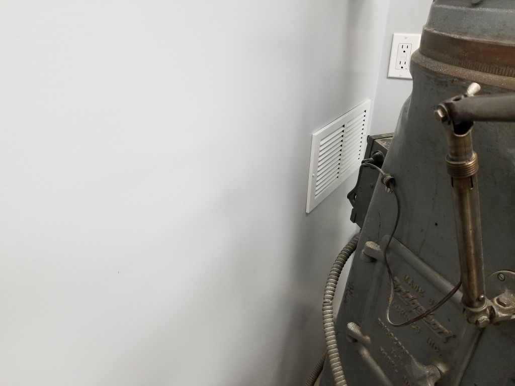
Return Vent: Having the collection bin in the mechanical room created a problem; the mechanical room is well sealed for noise reduction, so there was nowhere for the air exhausted from the filter to go. For heat/air to be retained in the shop, the exhaust air needed to return to the shop via a vent. Since I also wanted to keep the mechanical room noise level as low as possible this meant the vent needed to be sound proof. I built a sound proof vent by creating a 3ft long box and offsetting baffle plates inside of it. The sound has to reflect a dozen or more times off of the baffle plates; at each reflection it gets absorbed some by a fiberglass lining. The air, however, is able to snake around the baffles and find its way out. The inlet to this vent also points directly at the floor away from the sound sources. Somehow after adding this vent the mechanical room noise is actually noticeably quieter than when it was completely sealed. I think this may have had to do with the air pressure changes resonating in the previously sealed room, whereas now any fluctuations are equalized through the vent.
Control: For now control of the system is via a remote control outlet (repurposed from controlling the vacuum at the old shop), at some point I may integrate some low voltage switches with the blast gates so the motor will turn on as soon as any gate is opened.
