Piano Automation – Valve Control Board Build and Test
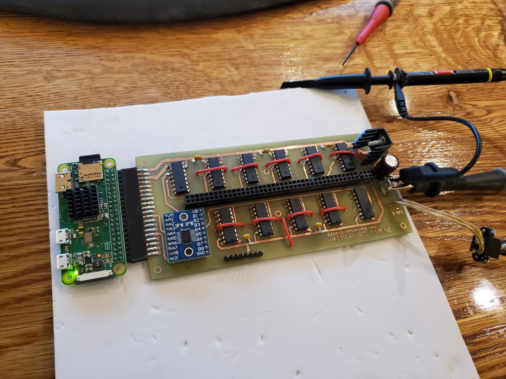
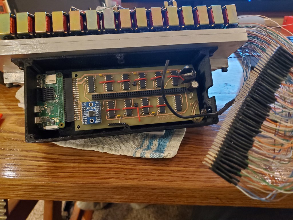
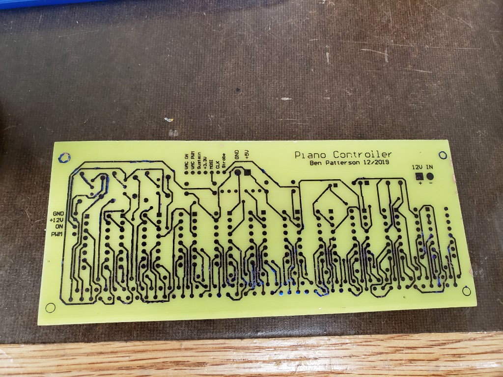
Last weekend I got around to populating and testing the piano valve control board. Unfortunately it did not work when initially powered on, I was able to track this down with a scope to problems with the level shift circuit between the pi and the shift registers. Rather than troubleshoot this farther I ended up re-designing and re-etching the board to replace my transistor array level shifter with an off-the-shelf level shifter sub-board. I also took this opportunity to #1 redesign the solenoid wire connections so that a pin header connection could be used rather than having the wires directly soldered to the board and #2 add a connector to the edge of the board to use the pi’s pin header connection.
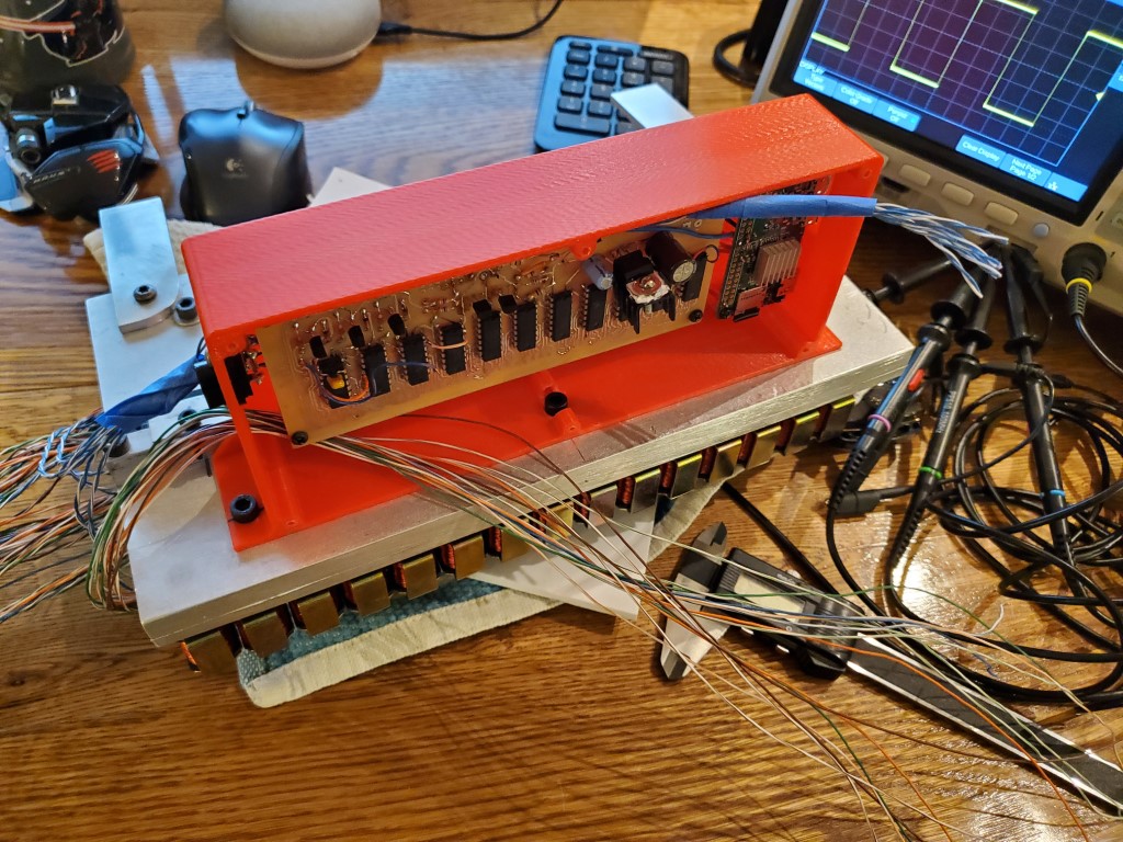
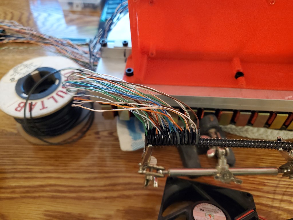
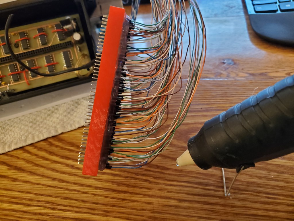
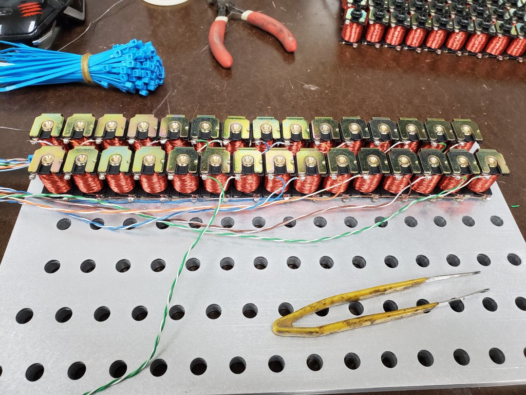
In the mean time I had also created a 3d printed enclosure to hold the board on the back of the valve bank. This was important as it allowed the final solenoid wire lengths to be determined and I soldered all the solenoid wires onto a pin header. I also 3d printed a support ring to stabilize the pin header and hot glued it all together to act as a single strain relieved connector.
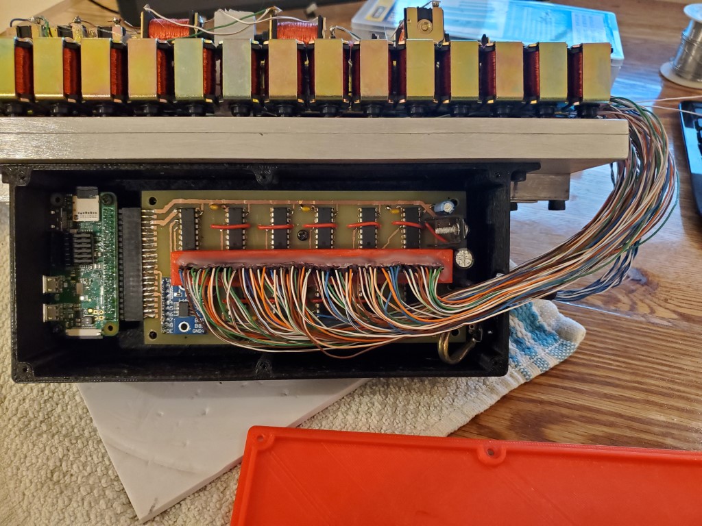
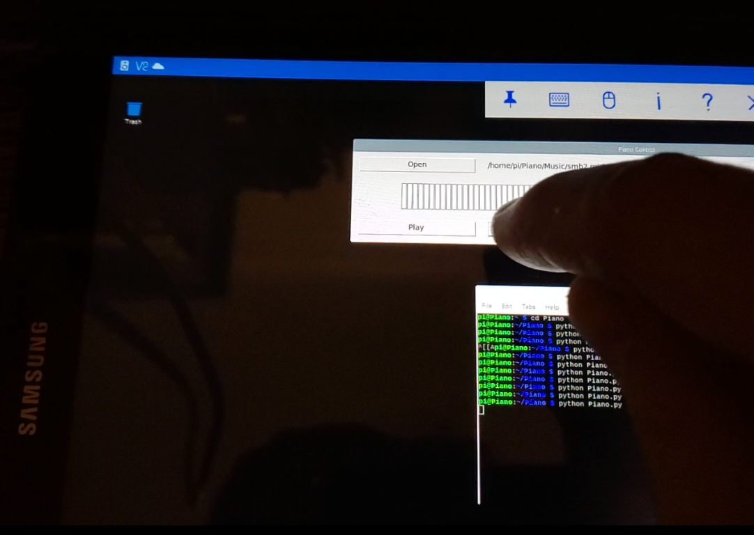
This weekend I was able to finish and test the re-design. All channels seem to be working OK and I’m able to control the piano keys individually from a tablet using a python script. I have some python scripts working that successfully decode the MIDI files, but I haven’t connected the dots between this and the hardware yet, that’ll be the next step along with hopefully adding a web interface.


Piano Automation – Valve Control Board
The Piano controller will be based around a Raspberry Pi Zero W. I had originally considered using a spare Arduino, however since the project will require a lot of file handling and a web server, having a full general purpose OS is much easier than shoe-horning it all into the Arduino. The Raspberry Pi also has a wifi adapter built-in, simplifying wiring.
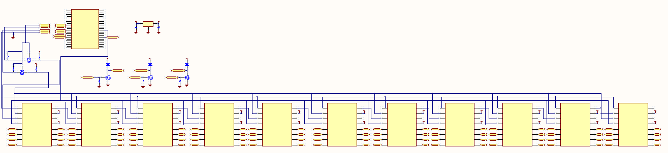
Unfortunately the Raspberry Pi doesn’t have the ~90 outputs that are needed to control the piano’s valves. This is a common problem in electronics and micro controllers – it’s assumed that the designer/integrator is going to provide their own output channels that are most suitable for their device. Instead, the Pi has several low voltage/current outputs that can be switched extremely quickly. I’ll connect these outputs to shift registers, clock all 88 valve bits into the shift register’s ‘memory’, and then send a signal to latch these new values to the outputs. This will be repeated quickly enough (~1000 times each second) that for my purposes the ‘remote’ outputs at the shift registers will appear to instantly follow the valve output commands from software.
74HC595 is an extremely common 8-bit shift register that many examples are based on, unfortunately it’s limited to 35mA outputs at 5V. This could still have worked, but would have required adding a transistor switching circuit to each output to achieve the 200mA @ 12V that the valves require. Going that route would have meant half of the design or more would have been dedicated to individual transistors/resistors, leaving a lot of room for errors during the build. To avoid this I found the MIC5891; this is essentially the same device as the 74HC595 but with built-in output drivers that can provide up to 500mA at up to 50V for each channel. The MIC5891 also has built-in protection for switching the valve’s inductive load, so this selection also avoided the need to add external protection diodes. The only minor problem created by the MIC5891 is that its inputs are all 5V and the Pi outputs 3.3V; this is resolved by a simple FET level shifter.
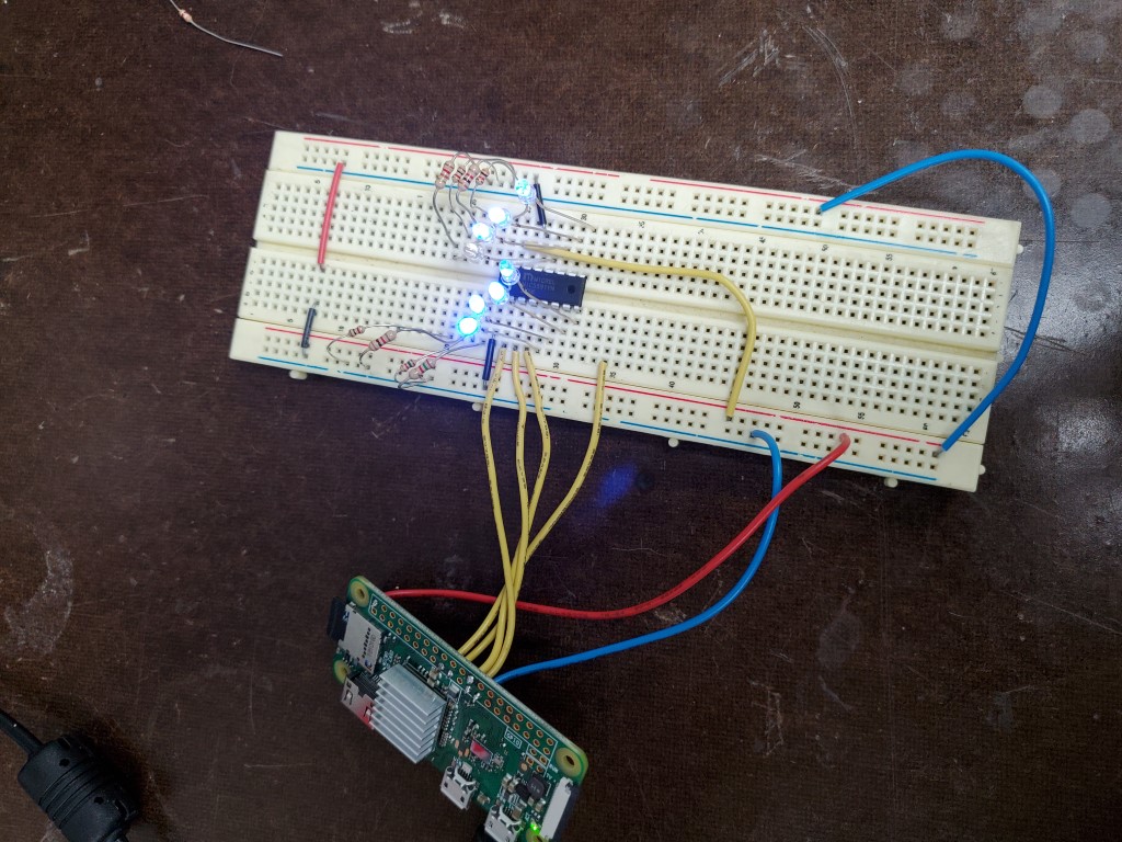
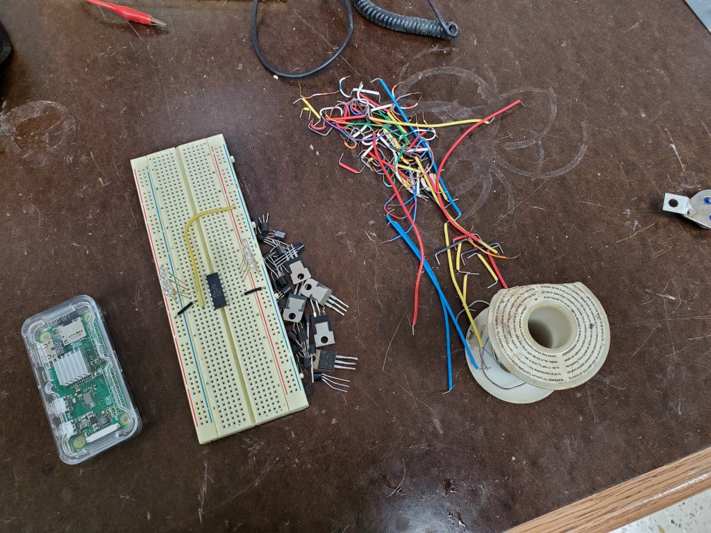
Once the MIC5891’s arrived I did a quick breadboard test with the PI powering a single shift register with some LEDs. In this test the MIC actually accepted the PI’s 3.3V signals, but I wouldn’t trust this to be reliable and will still include the level shifter on the full board.
To finish the design I added a few FET switches which will allow me to eventually route spare outputs on the Pi through this board to a satellite board that will control the vacuum pump (On/Off/Speed). I also added a 12V to 5V DC-DC power supply so that I can bring a single 12V supply into the control board and have it power everything, including 5V back out to the Pi. This was all drawn up in CircuitMaker.
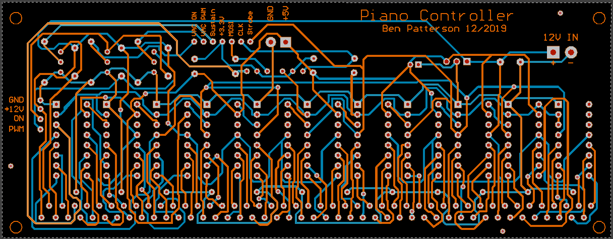
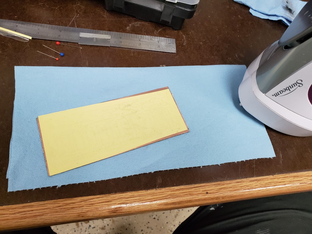
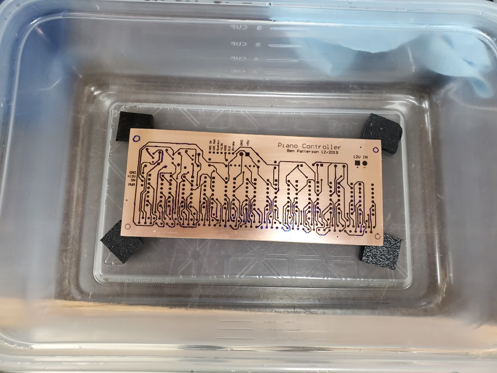
Creating the actual board consisted of printing the circuit design onto toner transfer paper, with scaling 1:1 and with the top layer mirror-imaged. I cut the board blank to size and drilled small holes that I had added to the design as alignment points. The board was then cleaned carefully with fine steel wool and denatured alcohol and then I ironed the transfer paper onto the board. When the board had mostly cooled I pulled off the transfer paper revealing the design. In the past I had used photo paper for transferring toner; this was my first time using purpose-made toner transfer paper and it definitely was much better – the board only required minor touch-up with a fine tip marker prior to etching. After etching in Ferric Chloride, steel wool and denatured alcohol were used to clean the toner/marker from the board.
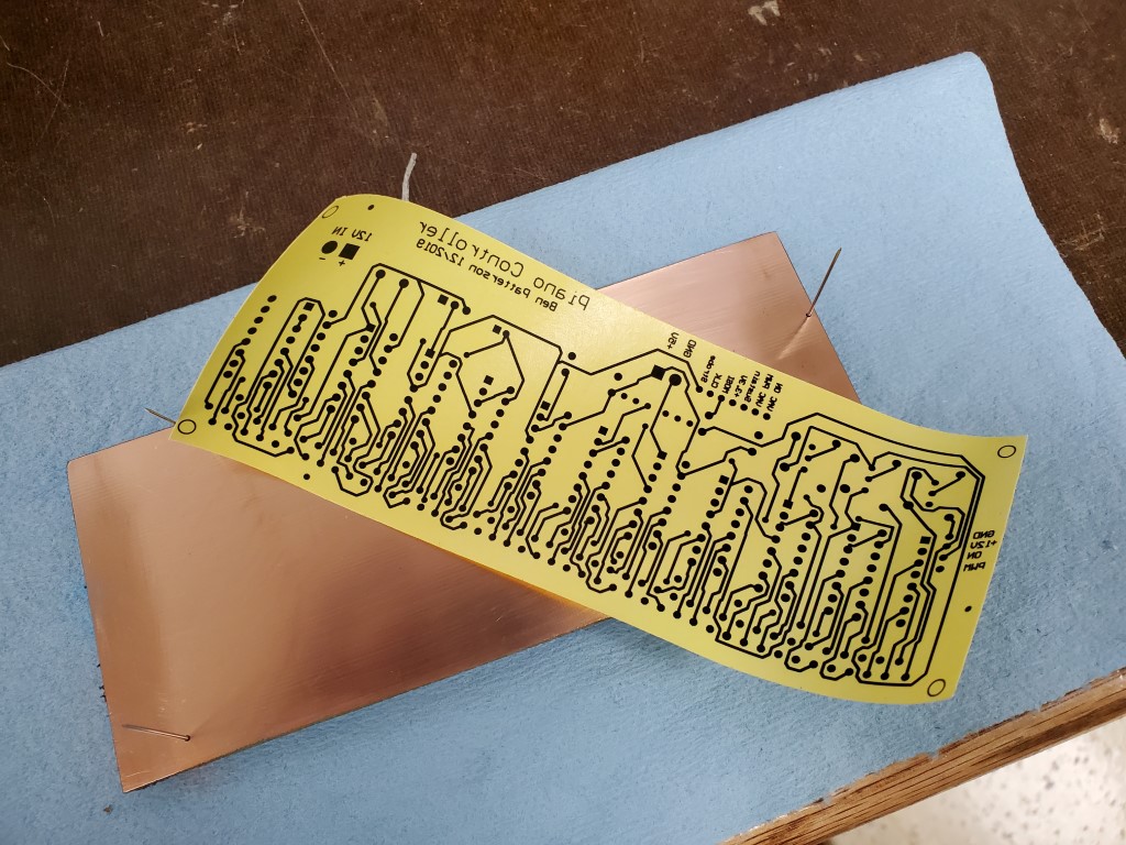

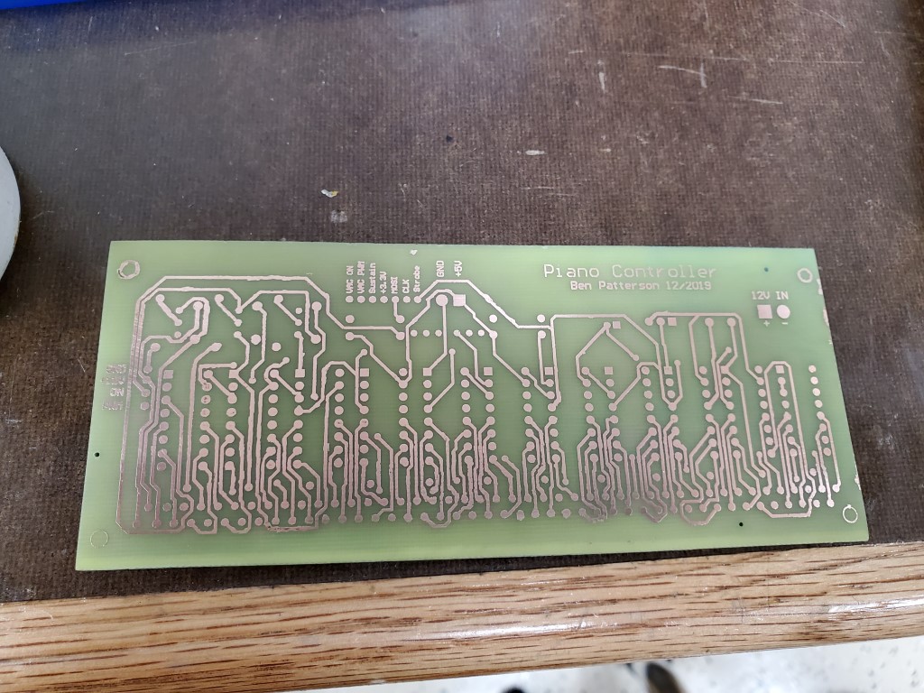
The next steps are to drill all the pin holes and to fully tin the board to increase the ampacity of the traces and prevent corrosion, I’ll do this prior to populating and testing the board.
Piano Automation – Valve Manifold Complete
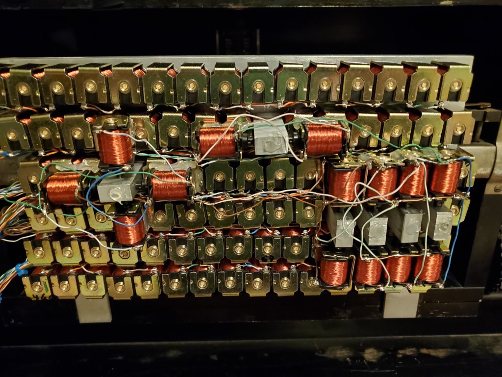
This weekend I had a chance to test the completed valve bank.
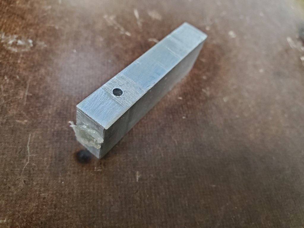
Testing revealed that some of the keys did not actuate with their corresponding valve open. On these keys when the valve (while turned ON/open) was removed from the manifold the key would strike immediately, pointing to lack of airflow through the valve as the cause. I can’t explain why this occurs on only some of the keys but the piano turns 100yrs old next year, so the inconsistency isn’t surprising. The piano could perhaps be adjusted to make these keys work the same as the rest, but I could more easily just provide more airflow via multiple valves per key – this is the approach I took. To connect multiple valves per key I created a few hollow standoffs that fit inside the valve holes in the manifold . The standoffs then have holes on their sides to allow connecting the extra valves on a 2nd layer above the rest. The end of the hole that was drilled to hollow the standoff was sealed with hot glue. Two valves solved the problem for most of the offending keys, but one extra special key required 4(!) valves in a ‘+’ configuration.

With the mechanical parts complete I’ve taken the first steps to construction of a raspberry-pi based controller that will use shift registers to power the solenoids. The raspberry pi and associated circuitry will be small enough to fit on the back of the valve manifold in the area where the paper roll would normally be. It has wireless connectivity and I plan to have it host a webpage where it can be controlled by phone/tablet. I’m bread boarding this first to prove the concept with one shift register, then once testing is complete I’ll create a circuit board to hold all 11.
Piano Automation Continued
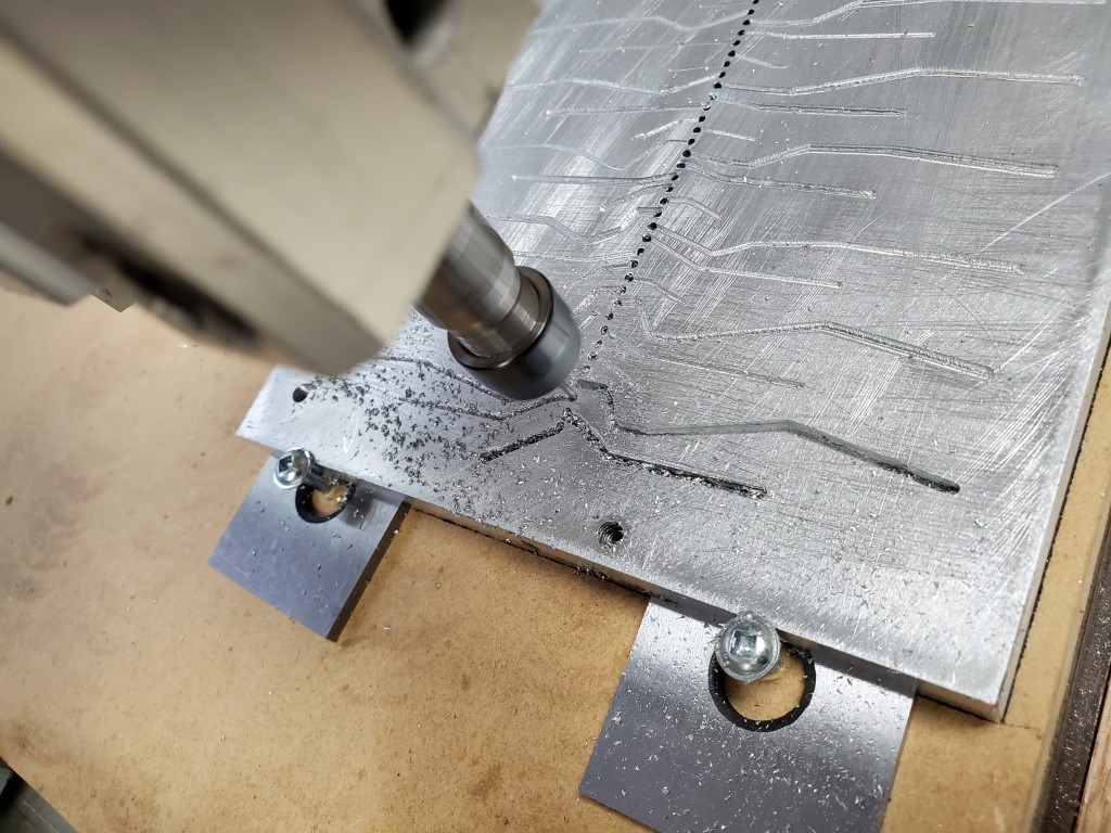
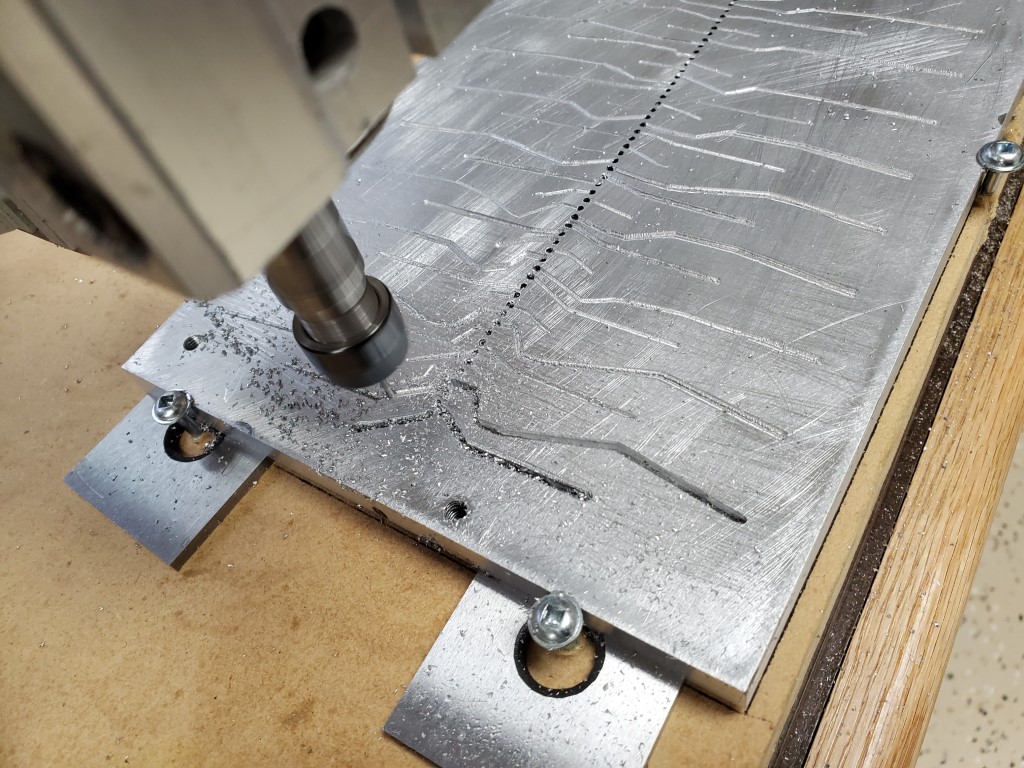
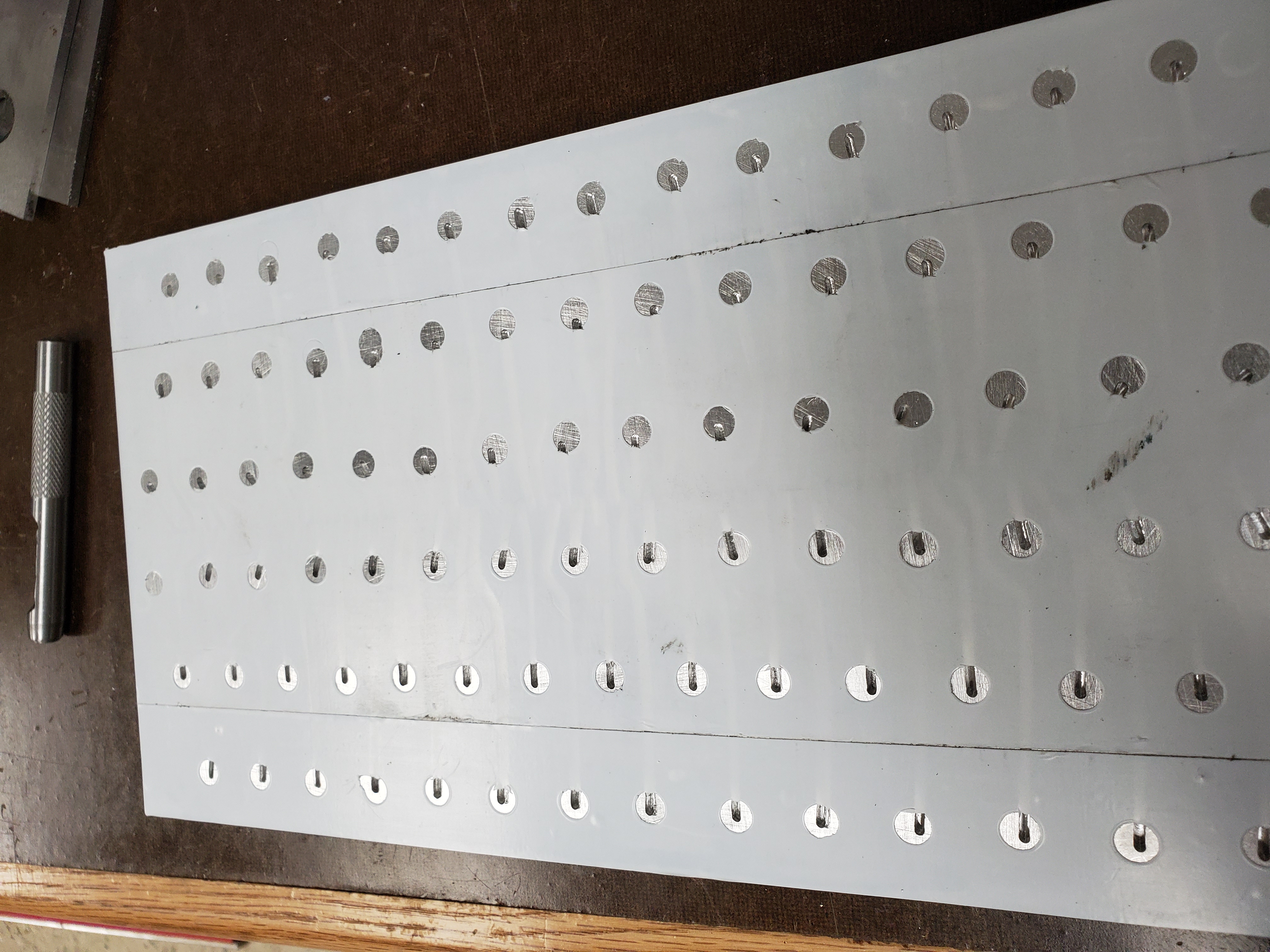
Over the past week I finished the lower valve manifold plate. The lower plate connects the row of holes on the piano tracker bar to the valves on the top plate. Obviously it would have been nice to just put the valves directly over each hole, but since the valves are much wider than the hole pitch I had to instead design the manifold with the valves arranged in multiple rows. Each tracker bar hole is connected to the valve above via passages that are routed into the bottom plate. The path of each passage was chosen carefully to avoid connecting to other valves/passages and to avoid running into the bolt holes that connect the manifold halves – each valve should connect to exactly one tracker bar hole. I let the CNC router do this work; it was relatively slow going with a 1.5mm end mill in aluminum but it turned out OK.
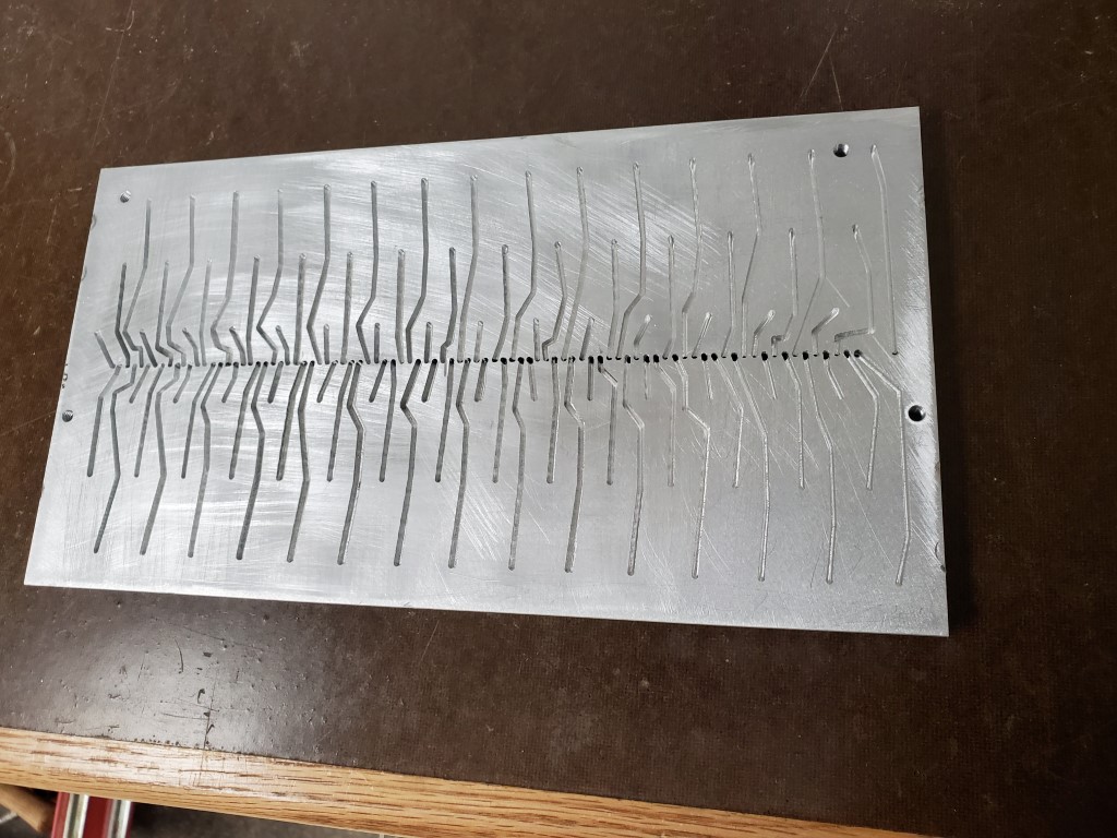
After the passages were milled I created a gasket using wide tape. The tape covers and seals the top of the passages and a hole punched at each valve location allows each valve to connect to its passage. The tape has enough compression that any imperfections in the plates will be sealed once the plates are bolted together. I also added a lip/shelf to the back of the manifold to hold it in vertical alignment against the tracker bar.
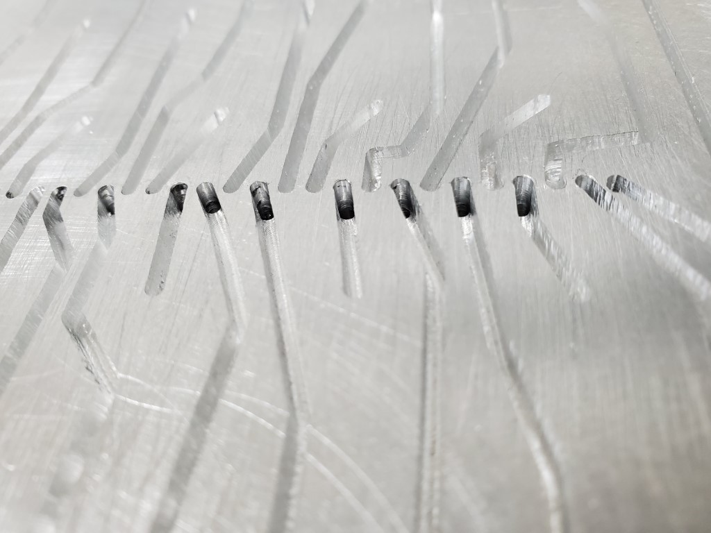
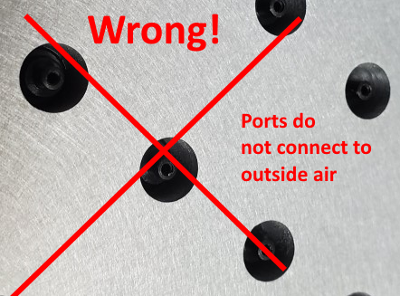
With the manifold ready, I connected it to the piano and tried firing the outputs. Results were not good, there was some vague correlation between outputs being on and notes being played but something was wrong. I had originally assumed the air passed all the way through the valves but closer examination revealed that they actually pass air from their stem to ports near the base of the stem. Since I had the entire stem/base of the valve mounted inside the manifold there was nowhere for air to flow when the valve opened. I re-made the top plate with smaller holes and re-installed the valves with only the stem in the manifold.

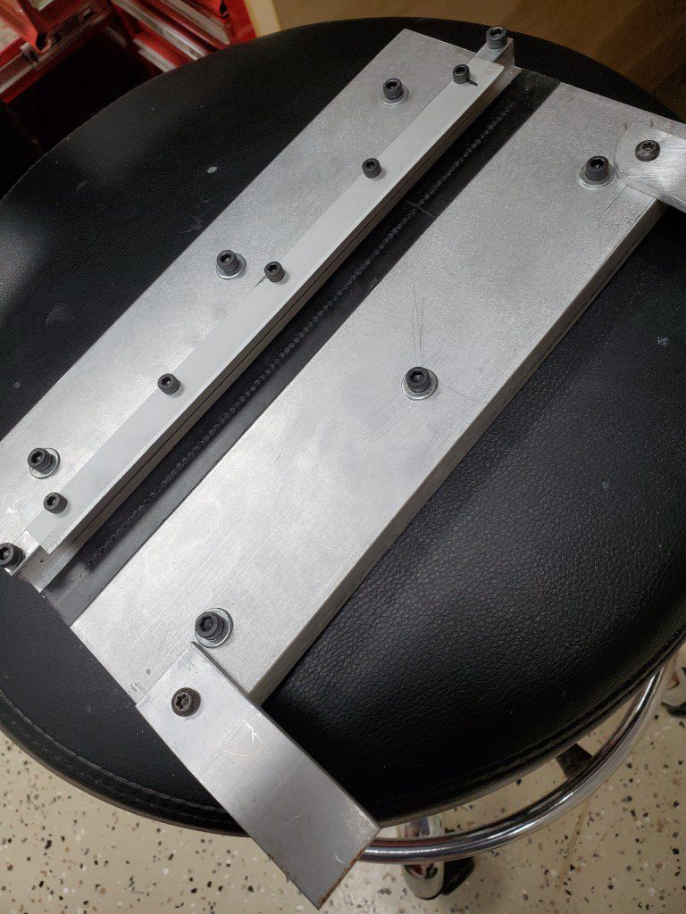
Remaking the top plate solved the valve problem but there were many dead notes due to air leaks at the tracker bar. I experimented with several materials to seal the tracker bar to the manifold and ultimately landed on thick rubber outdoor electrical tape as the best performing, though many leaks remained. I found that the tracker bar was not very flat and I was able to carefully bend it back. This helped considerably but leaks still remained. I found that the force needed to push the manifold against the tracker bar for a good seal had the effect of bowing the tracker bar away from the manifold in the middle, so I added a thin aluminum lip to the shelf on the back of the manifold. The lip is just thin enough to fit between the tracker bar and the wood cover behind it and it allows the manifold to hook over the top of the tracker bar and more positively hold the bar along the entire length of the manifold with enough preload on the tape to seal. This essentially solved the leak problem.
Currently there are ~12-15 keys that I’m tracking down problems with, this started from ~20 and was reduced by working through electrical/alignment problems. On the remaining dead keys I’ve ruled out problems on the piano side, problems with the lower plate, and any electrical problems; so next step may be replacing the valves themselves. It’s possible that those keys need more airflow, which would require milling their passages deeper and/or modifying the valves; hopefully it doesn’t come to that. Once they’re all firing though then the mechanical work on this is basically done and I’ll be able to shift focus to the control system side.
Piano Automation Begins
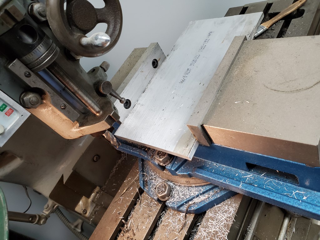
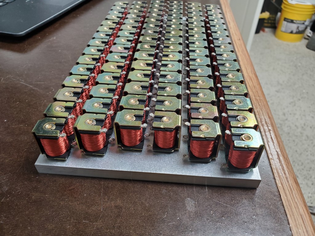
This weekend I designed and began fabrication of the parts needed for adapting the solenoid valves to the piano’s tracker bar. This adapter will consist of two 3/8″ aluminum plates. The top plate will have holes to accept the solenoid valves, and the bottom plate will have holes to interface with the piano’s tracker bar. Grooves will be machined into the bottom plate to create airs channel between the tracker bar holes and the solenoid valves above. The two plate will then be sealed together, covering the grooves; a similar construction technique as some carburetors. As long as the grooves are carefully routed, each valve should connect to exactly 1 tracker bar hole.
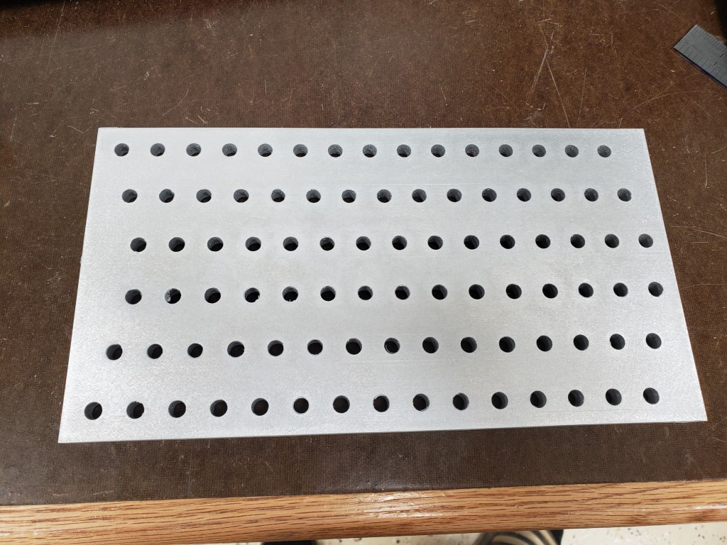
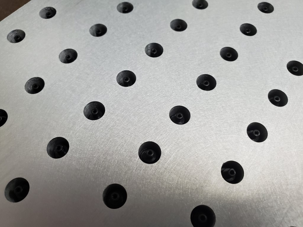
I cut the 3/8″x6″ plate on the band saw and then milled to final length. I used an edge finder to locate the plate edges, and then used the mill’s digital readout to position above each row/hole. For each row I took 2 passes, first spot drilling with a center drill and then drilling to size with a twist drill. 88 * 2 plates * 2 passes = 352 cycles of positioning the X axis and drilling a hole. Once all the holes were drilled I sanded sides to remove burrs from the holes and scratches from the rough plate.
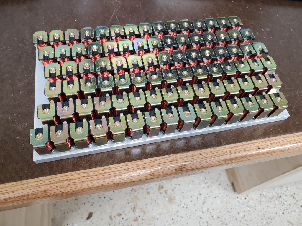
Next I installed and wired the solenoid valves in the top plate. The solenoid valves are an exact fit to the hole, but I added a bit of CA glue to ensure they stay in place. Wiring consists of scrap Ethernet cord that’s been stripped back; Every ~7 solenoids each share a common wire to reduce wiring, but it’s still ~100wires.
I’m happy with the results so far; this is by far the most precise thing I’ve made on the mill and everything is lining up perfectly. The next step will be to 3D model the grooves and convert these to paths to run on the CNC router. I’ve done some aluminum milling with it previously so it should work out OK, especially since it’s just cutting the shallow grooves – I wouldn’t have trusted the router to drill the holes as well as the mill did.


Piano Automation Proof-of-Concept
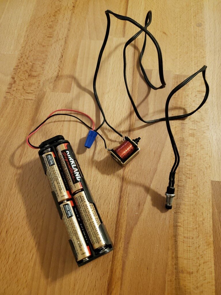
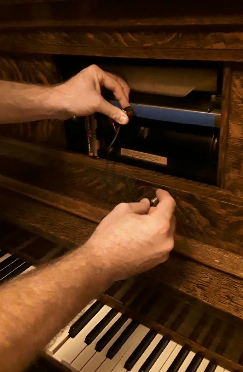
I did a quick test tonight to check/confirm the feasibility of using the ebay solenoid valves I got a while back to control the player piano. I connected one of the valves to a 12V battery pack and a push button, and then held it in front of one hole of the piano’s tracker bar while the rest were taped closed. When I pressed the button, the valve opened, and the piano played the key! With this successful test I can move forward with designing an adapter to connect all 88 valves to the tracker bar.
Hacking the Player Piano – Part 1
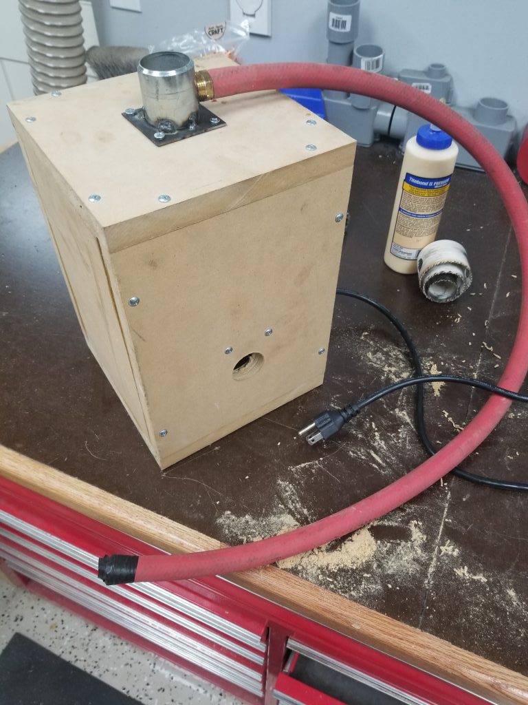
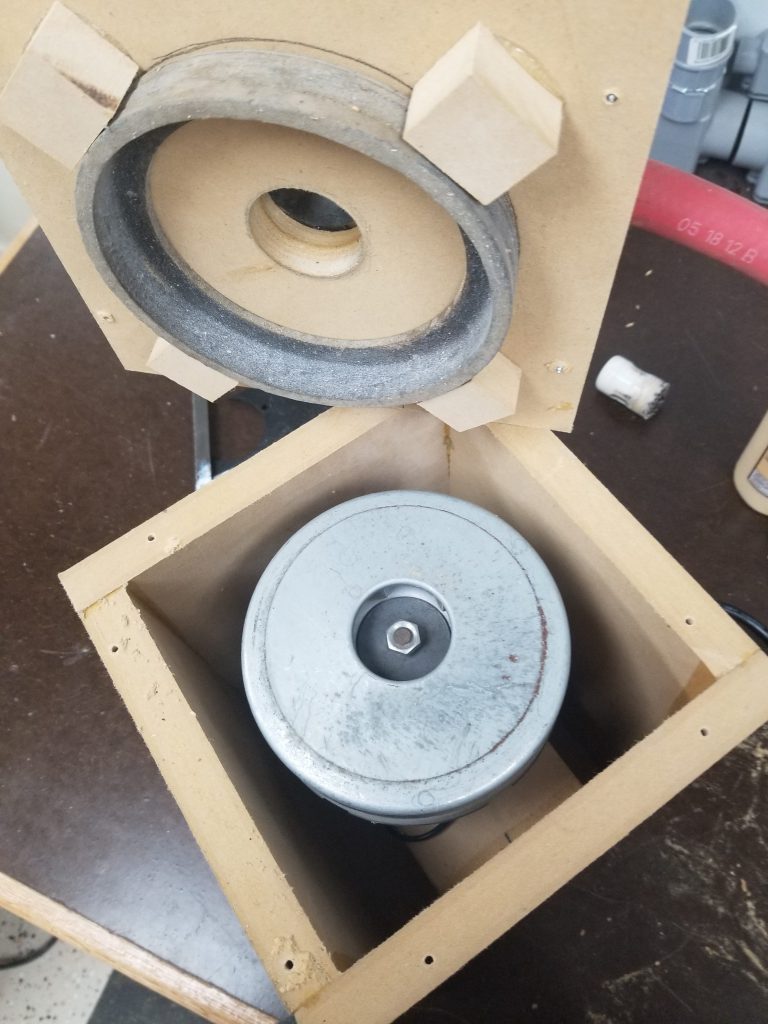
It was only a matter of time before this happened – the player piano (original post) is a real workout to play manually. Since it works on vacuum, I had set aside the motor from an old vacuum cleaner for potential use in powering the piano. Tonight I built a small box to contain the vacuum motor and connect it to the piano. The box is made from MDF, partly because I had scrap that needed to be used, and partly because it’s very heavy & sound absorbing. I made the big fitting by cutting/milling a square from scrap, I then bored a hole in it on the lathe and welded it to a scrap of pipe.
One very large hose goes to the manifold powering all the key bellows, and another smaller hose powers the vacuum motor for the tracker/scroll mechanism. I didn’t notice the smaller connection at first, so I had to go back and tap a fitting into the connection for the large hose; there’s still enough room for both to connect though.
Overall it seems to work great, this effort was definitely a quick proof-of-concept though and I’ll need to go back and fix/test a few things:
#1 – Motor controller to slow down the vacuum motor. Currently it has way more vacuum than is actually needed and slowing down should reduce noise from the motor.
#2 – Ensure cooling is OK. Especially after slowing the motor down I need to test that air flow is good enough to keep the motor consistently cool.
#3 – Mount in piano base and complete further noise insulation.
#4 – Tee hoses (and potentially add check valves) so that manual operation still works.
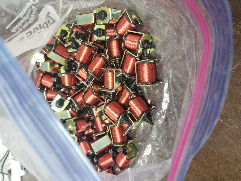
Beyond that I do have plans to eventually (could be tomorrow, could be in 5yrs) automate the player mechanism using some small pneumatic solenoids I found on ebay. These would tee off of each line from the tracker bar and when they open it would simulate a hole in the paper passing by. With this it would then be computer controlled and able to play anything. By default these are off/closed, so the paper mechanism would still work fine, in computer-controlled mode I’d just need to block off the tracker bar holes with some tape.

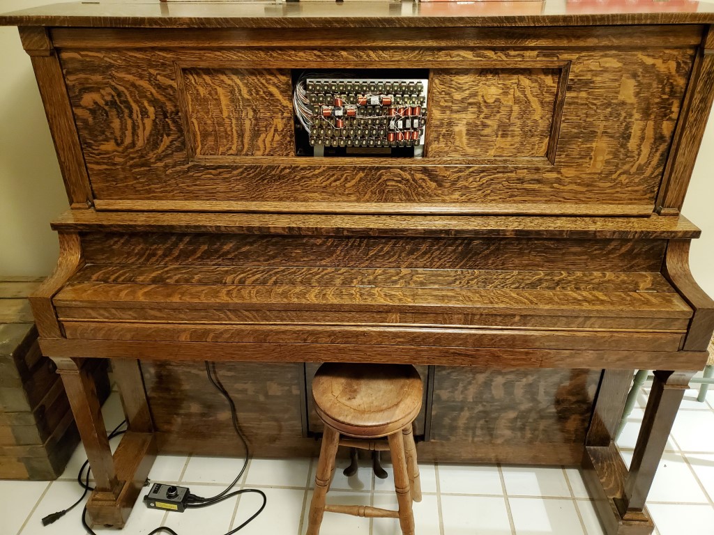
Piano!
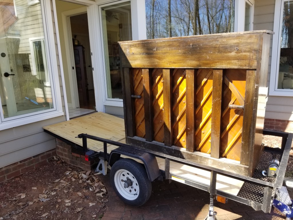
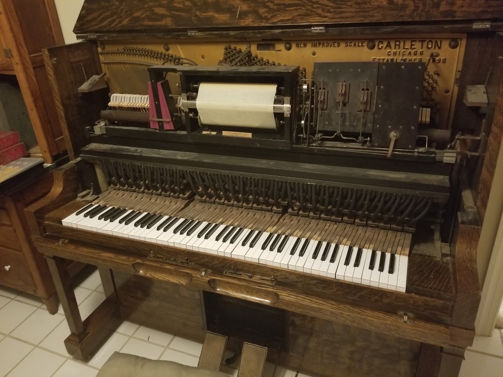
Christina has had an eye out for a piano for a while. Interestingly the standard price for used pianos is ‘free, must be able to move’. With this in mind we were shopping on ease of moving – looking at the surroundings in the listing photos to determine where it likely was (i.e. garage vs inside) was almost as important as the piano itself. The right one popped up this week, so this weekend we took the trip to pick it up. I had a particular interest in this one also since it’s a player piano. Player pianos are one of the earliest (the earliest?) wide-spread programmable automated ‘machines’; it’s fascinating to see how these were designed to be built using mostly hand-made parts and to operate without electricity.
Moving: Pianos are the archetype of things that are difficult to move. The trick, as usual, is letting the equipment/physics do the work. At the pickup side it was already in a garage; after backing up near it I jacked the tongue of the trailer up so the ramp/bed formed an even & shallow slope. I was ready with the winch at this point, but because their driveway sloped away it actually rolled onto the trailer without needing it. To unload, I backed the trailer around the back of the house to the back door and then raised it up on jack stands until it was about even with the threshold. We then put a 4×4 timber across the bottom of door frame of a nearby interior door and used this as an anchor point to winch the piano inside with ratchet straps. Once it landed on the tile floor it was easy to push around.
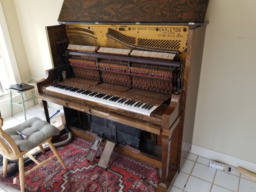
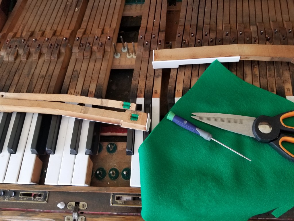
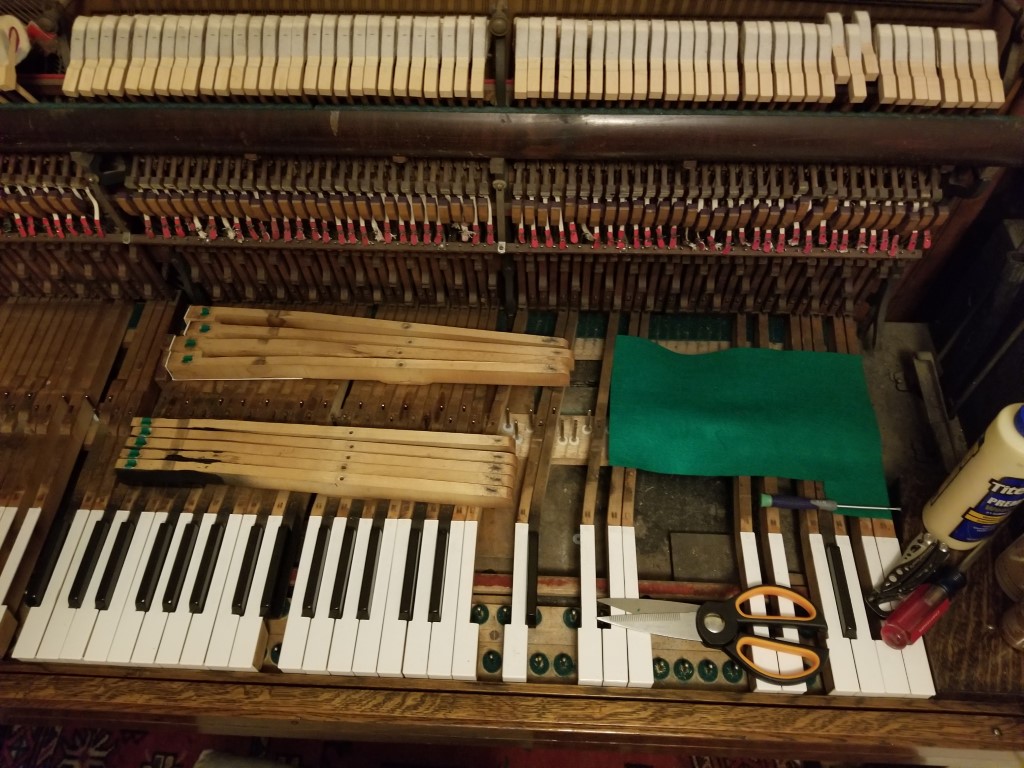
Rebuild: As near as we can tell from the serial number the piano seems to have been built in 1920. It was also signed inside with a 1996 date, likely associated with a rebuild. The good news is that everything seems to be in place and after sealing a few vacuum leaks it was able to play automatically; It definitely had/has room for improvement though. I was able to make it sound noticeably cleaner by dialing in the correct ‘capstan’ height on the back of the keys. The next priority is getting the keys working more consistently; several of the keys (~40) were missing felt from their front hole. The front hole felt prevents the key from wobbling side-to-side. Several keys (~20) also had cracks where the back hole goes through the key. The back hole is where the key pivots, so these cracks allowed the keys to tilt side-to-side. Felt was added to the front holes and the cracked back hole parts were glued back in place; this resolved the loose key problems. For just a few keys (3) the cracked part is missing and I’ll need to create and glue in a repair piece. Once I’m finished rebuilding the keys I can then go through and set the key level and adjust the hammer action. Along the way I’ll also be coming up with an electric vacuum pump – pumping with the pedals is a work out!