Sliding Doors
The shop floor plan allows for a large opening between the ‘far’ end of the shop and the auto repair/bus area. This will allow tools to be easily shared between both spaces; during a big auto project the repair bay can become an extension of the workshop. The opening is also big enough to bring in the front or rear of a vehicle if ever needed. When auto projects aren’t underway though I’d like to have doors cover this opening to prevent dust/mess from wood/metal project leaving the shop area and to save on shop heating/cooling costs.
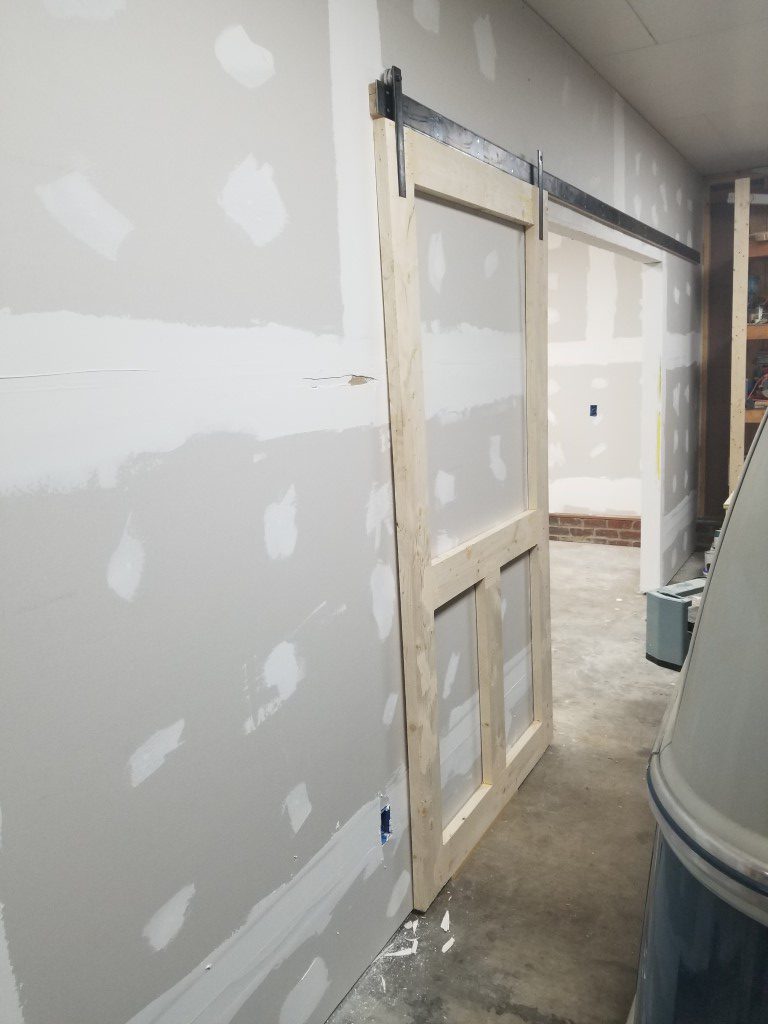
The size of the opening presents a problem – swinging doors would have to swing ‘out’ of the shop to avoid hitting cabinets, and the large sweep would require moving anything parked on the garage side out of the way temporarily, kind of a hassle. To avoid this problem, sliding doors made the most sense.
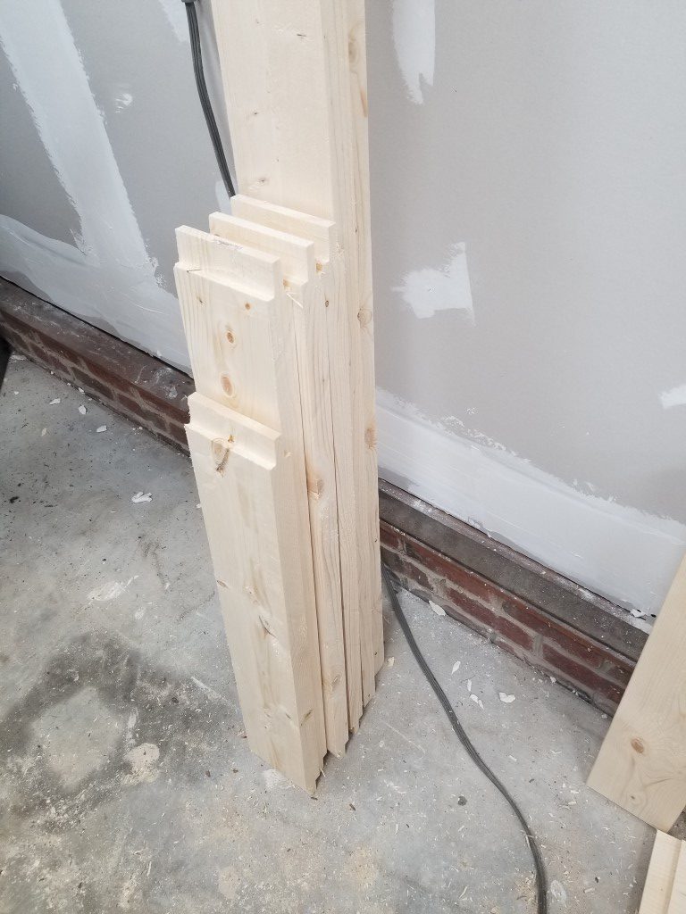
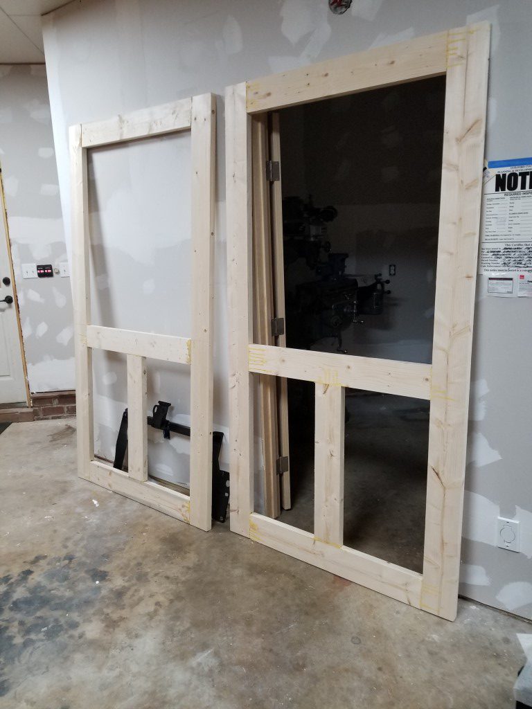
The shop build project is being run with the materials cost set to minimum and the end-product quality set as high as is practical. This sounds unrealistic but is actually possible with the trade-off being time; it’s not a problem though since I count this as hobby time and there’s no particular deadline. The sliding doors are a great example of this – sliding doors and hardware are outrageously expensive compared to the raw materials cost. Building my own also gives me full control, in this case I wanted to avoid the farmhouse/barndoor/rustic look in favor of cleaner traditional/modern look. Over the last few weekends I’ve built the doors and tracks below, key points:
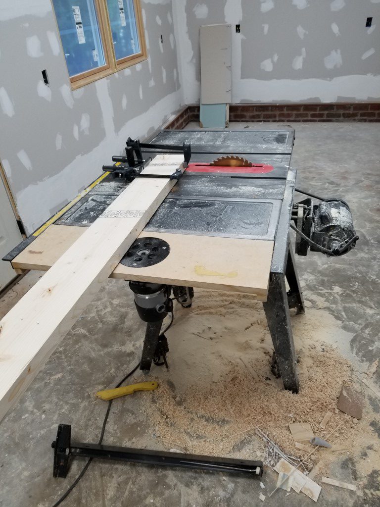
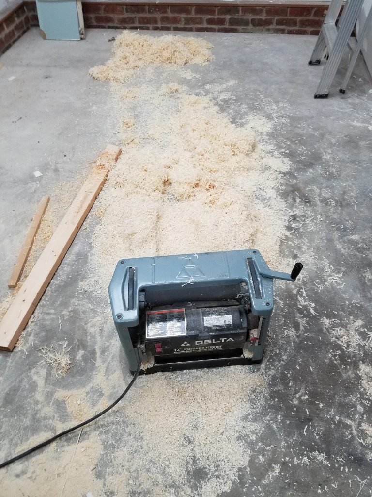
- Door frames from 2×6’s, planed down to standard 1 3/8″ door thickness
- Mortise and tenon joints connect frame pieces (tenons via table saw dado stack, mortises via router and chisel)
- Slide rail is two 3/16″ x 3″ x 10′ flat bar sections welded in the middle.
- Door bracket pins turned and threaded on lathe then welded to brackets.
- Aluminum rollers turned on the lathe, held to the brackets using standard 608 skate bearings.
- Brackets recessed into door frame and secured to the doors with studs welded to back side for a completely smooth front.
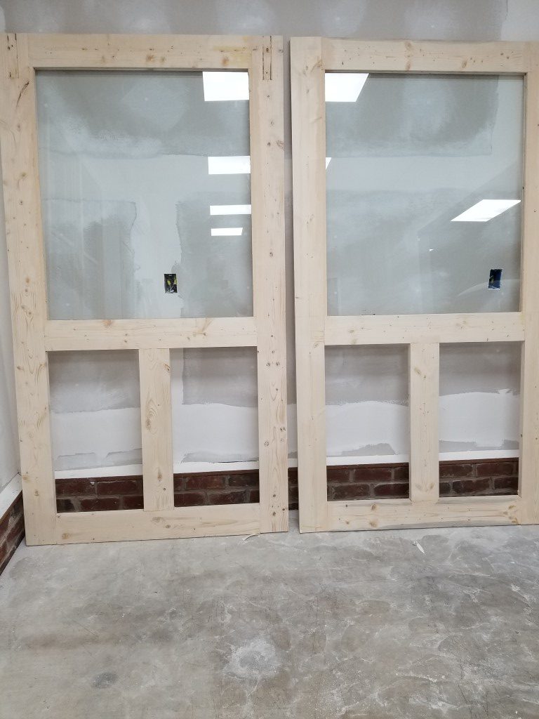
- 1/4″ Tempered glass sourced from local glass shop.
- Groove along bottom of door and small bottom bracket keep door located against the wall and limit inward overtravel.
- Roller to door top spacing and roller flange width prevent door from lifting/falling off rail.
There’s a good bit of finishing work still left, but I’m happy with the results so far.


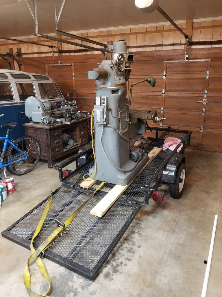
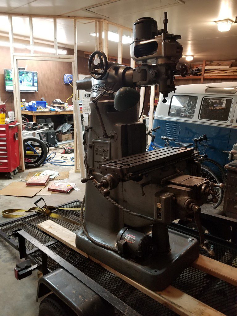
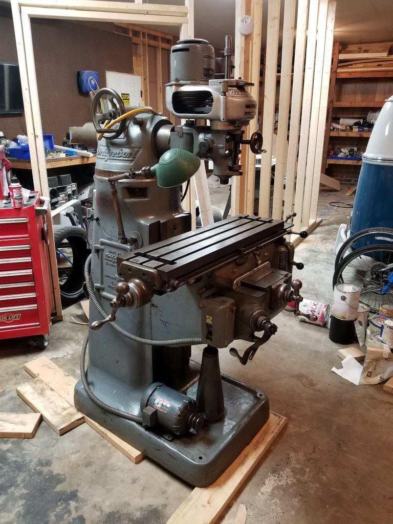
The Bridgeport has landed
I’ve had my eye out for the last few years for a milling machine to expand on machine shop capabilities. Finally this weekend I was in the right place at the right time to see the right listing come up and jump on it. As Bridgeport-style milling machines go it’s on the smaller side, but for my purposes this will be ideal. It was built in 1942 and is one of the early the “round ram” style machines with an “M” head. The previous owner has a makeshift rotary phase converter installed; consisting of a larger 3phase motor and a rope to pull-start it. This works fine for now but I may eventually replace it with a variable frequency drive.
How to move a mill had always been a concern when considering getting one. It weights in at ~1800lbs (the bus is ~2300lbs for comparison), which is exactly at my trailer and tow vehicle’s listed rating after adding the weight of the trailer itself. I think the rating has more to due with structural limits though and it did fine with plenty of power/brakes on the ~30mi trip. Loading was a breeze since the seller had an overhead crane.
The mill’s weight is concentrated in a small footprint with a lot of the weight being relatively high-up; 2×6’s were used to distribute the load across the trailer structure rather than the weak mesh floor. I had not considered the height and got lucky that the top of the mill while on the trailer cleared the garage door by about 1/2″. It wouldn’t have been a problem really, but this made the difference between unloading inside vs outside. During unloading the trailer and ramp were supported with wood cribbing and the mill was inched along using ratchet straps and a long metal bar. As long as you don’t get in a hurry with moving heavy stuff the worst that can happen is that it takes forever.
(Also shop is in-progress in the background, walls starting to go up)

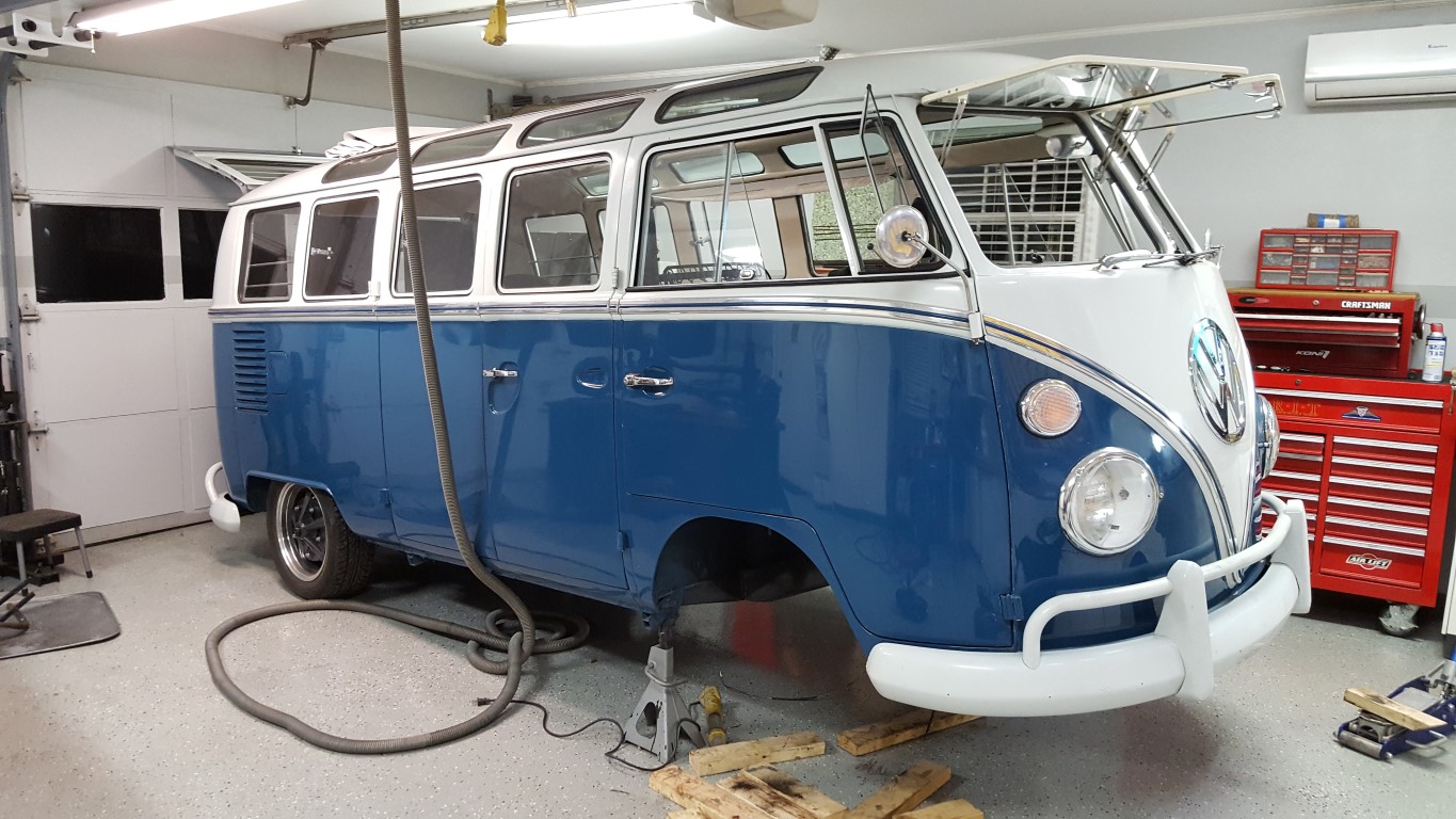
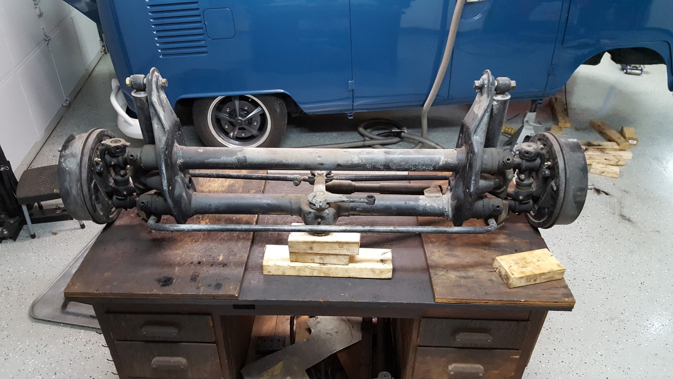
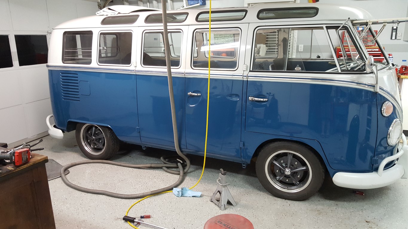
VW Bus Adjustable Front Beam
During the original bus rebuild I had ‘flipped’ the front spindles to lower it some. Stock height on buses was alarmingly high, lowering allowed for better handling and gave the possibility of the bus fitting in the garage with a roof rack. The spindle flip, however, lowers by a fixed 4-5″; just low enough that the front wheels would rub the wheel wells during bumps or heavy braking/cornering. Cornering was particularly exciting since the outside wheel would rub, slowing down that wheel with the tendency to make the turn tighter – or “positive feedback” for those of us that are into control systems (not a good thing).
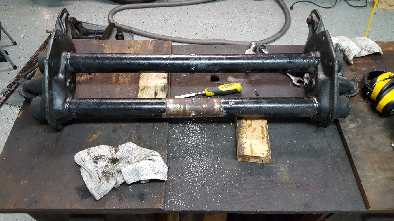
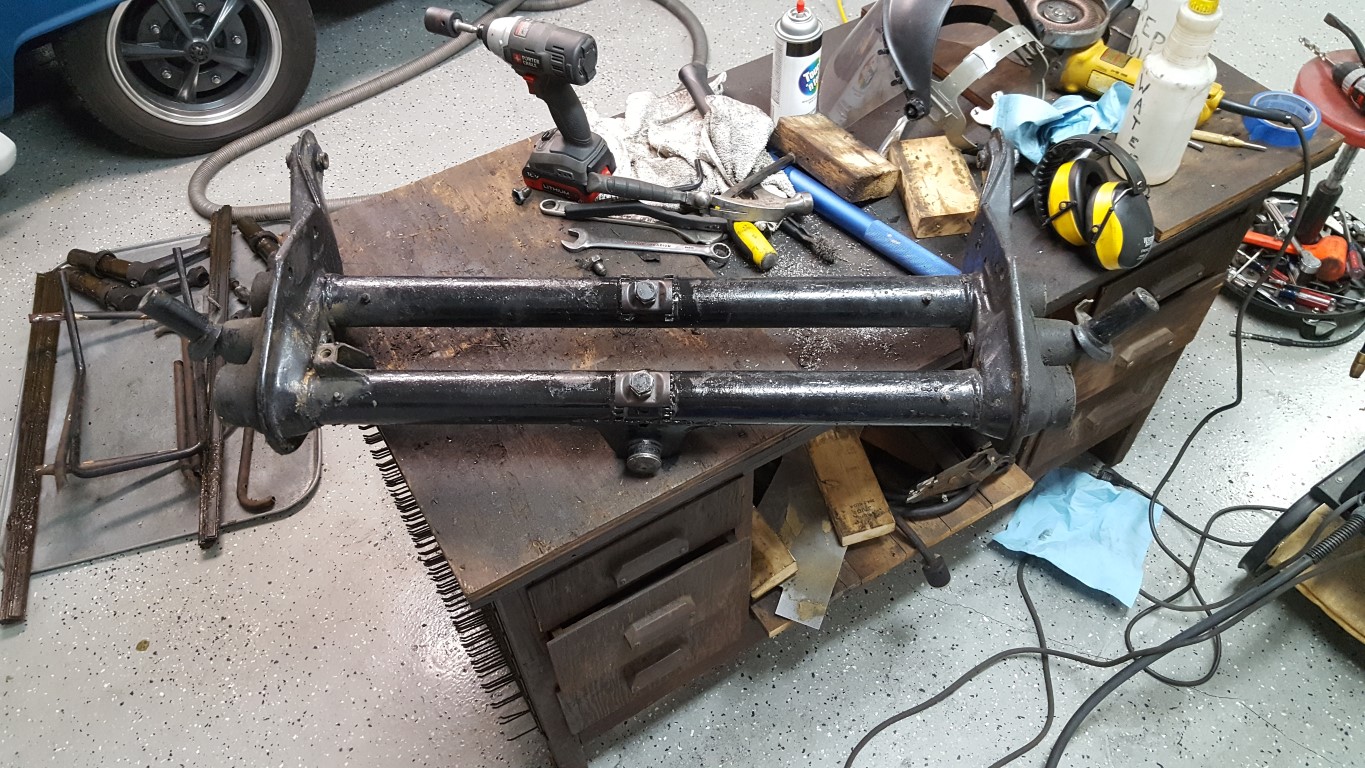
To remedy this, a way was needed to raise the front back up an inch or two. Old VW’s use a very unique front suspension design with two sets of torsion leaf springs inside of a beam with two tubes. The leaf spring packs are held fixed in the center of each tube and are capped at both ends with the four trailing arms. Minor raising and lowering can be accomplished by changing the angle the springs are held at the fixed center point. The center spring holder is held by divots crimped into the tube which engage with holes in the spring holder; these divots were drilled out which freed the holder. Toothed sections were then welded to the tubes; when the center is bolted in place a nut is tightened against a toothed plate that engages the teeth, holding the torsion spring pack at the new angle.
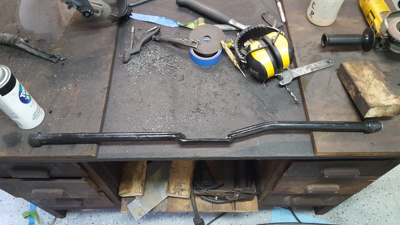
Lots of things had to be disconnected and then reconnected to get the beam in/out. This made it a greasy, awkward, and tedious job but overall it went well. The only hiccup was that after the beam was re-installed the shift linkage interfered with the adjuster bolts, though I had read this could happen. To solve this problem I welded a chunk of plate steel to the bottom of the linkage to hold the geometry and then ground out a strategic section of the linkage tube. The plate is as strong or stronger than the tube, and it’s in just the right spot to clear everything above/below it. After everything was back together the bus is level and no longer rubs the front wheels!
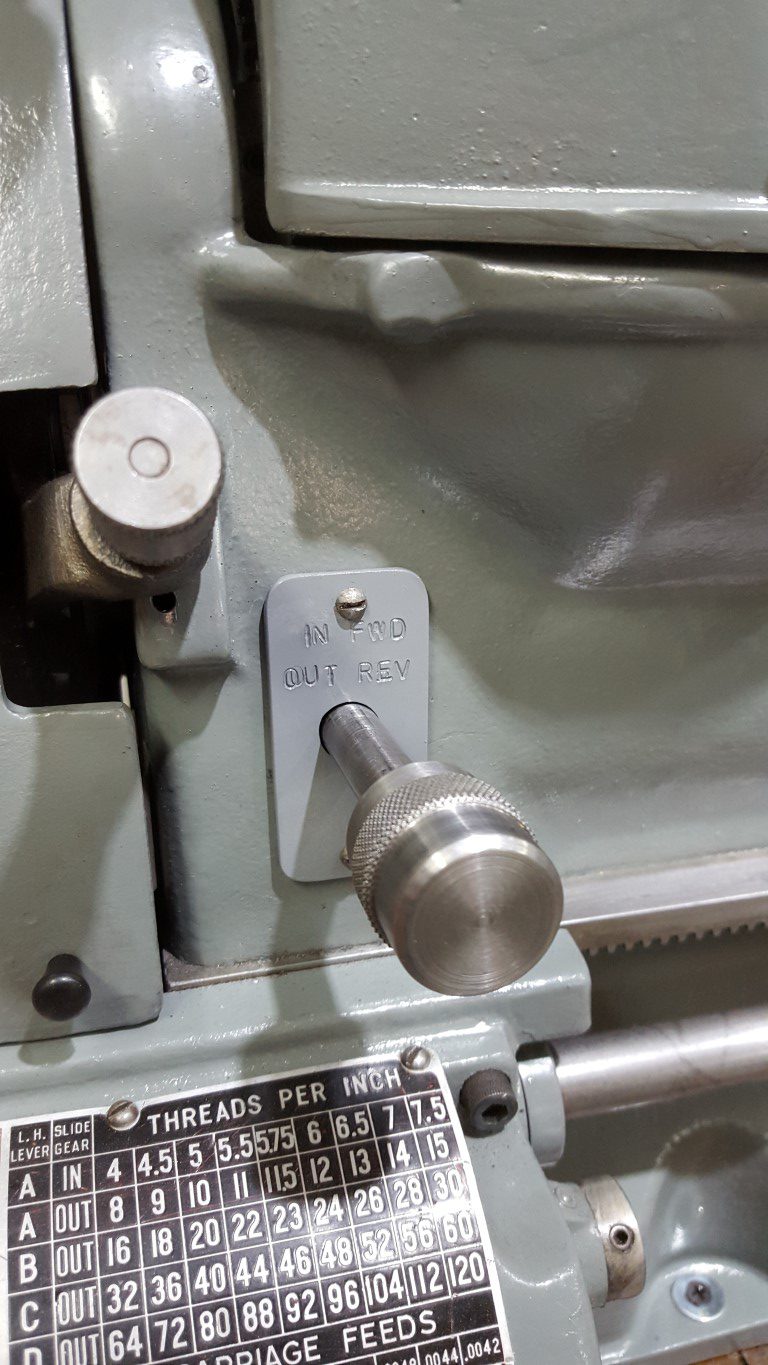
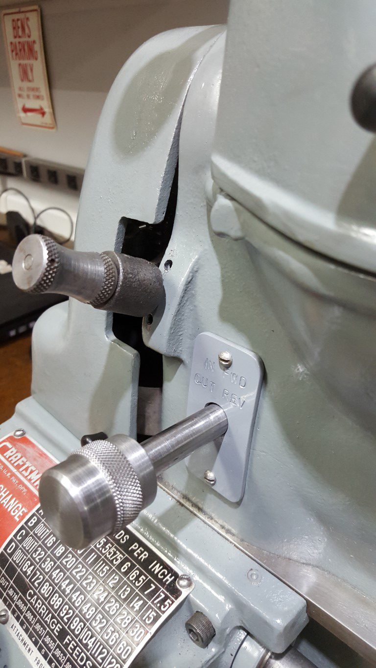
Atlas/Craftsman Lathe Reversing Switch – Finished
Tonight I finished up the lathe reversing switch linkage by stamping and painting the cover plate and making a knurled knob that roughly matches the others on the lathe. The lathe allowed the inside diameter of the knob to be bored precisely enough to get a good interference fit on the shaft – no need for any fasteners.

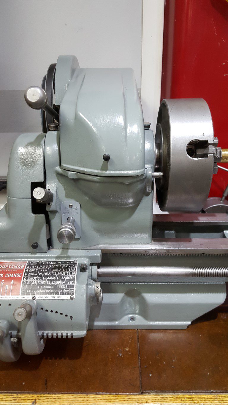
Atlas/Craftsman Lathe Reversing Switch
Originally the Atlas/Craftsman lathes spun in only one direction; because of this they came with only an On/Off switch integrated into the lathe’s headstock. At some point in my lathe’s past the On/Off switch was removed and a reversing ‘drum switch’ added. The drum switch gives the flexibility to spin either directions for special uses (cutting metric threads, power tapping, etc) however it’s it’s too big to fit in the lathe’s headstock.
The previous owner had the switch mounted on a wooden arm extending up from the lathe’s workbench; re-using this idea would work but since I’ve moved the lathe to the shop countertop the arm would need to be rebuilt and I also don’t like the aesthetics or the need to reach over the spinning work to turn it on/off. Another option would have been to mount the switch under the lathe base, however for the carriage to clear the switch would require raising the lathe – it was already at a good working height and raising would effect stability/rigidity as well as being susceptible to dripping oil. Lastly, it could have been mounted just anywhere on the ‘outside’ of the lathe (on a guard door, past the tailstock, etc) – none of these locations seemed great and overall this just seemed like giving up.
So what I ended up doing over the past few nights was locating the switch in the only volume of space just big enough for it, under the motor. This location has the added benefit of making the wiring short and simple. As-is, this is of course very inconvenient, but I chose it with creating a linkage in mind. The addition of the linkage allows the original On/Off switch hole to be utilized (previously this was just an open hole), puts the control in a convenient place, and makes it look like it was designed this way. The linkage was a challenge and took a few iterations to get right. It consists of a 1/2″ OD steel tube that runs through the headstock, supported by two metal plates I fabricated. At the end of the tube I welded on a nut to accept a bolt that bolts on another arm I fabricated. The arm has a bolt welded through it that engages with a slotted lever welded to the drum switch’s lever. The resulting contraption actually works very smoothly: pushing IN runs the spindle forward, pulling OUT runs it reverse, and returning to center is Off. All that’s left to do is create a matching knob and mark/paint the switch plate.

Atlas/Craftsman Lathe Carriage Hand Wheel Fix
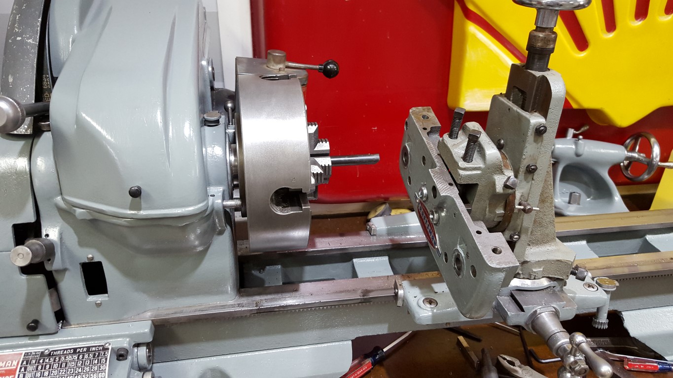
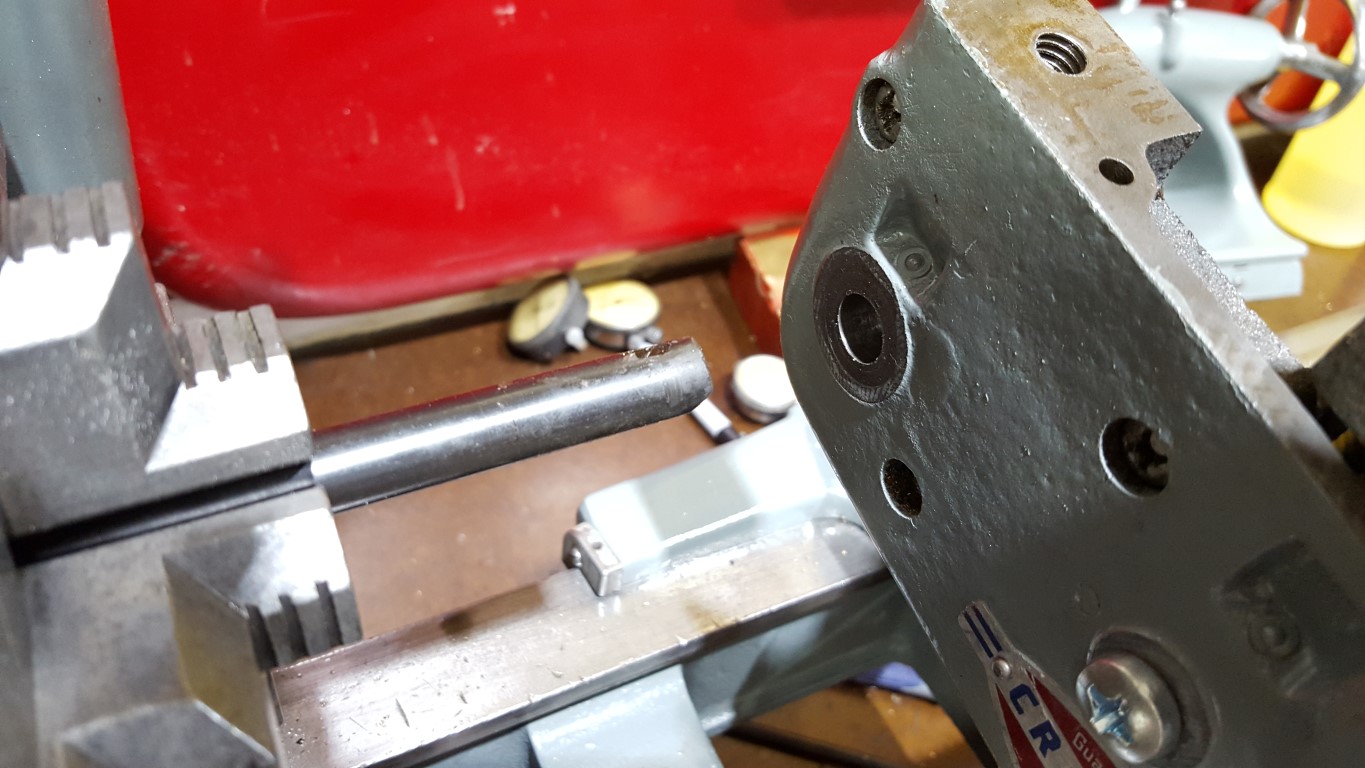
The hand wheel for the carriage (longitudinal/Z axis) of the lathe had a bit more up/down slop than I liked. To remedy this I used the lathe to fix itself. First the ‘apron’ (front plate) was removed from the carriage and mounted in the milling attachment, the smallest boring bar that came with the lathe was used to widen and true to the hand wheel hole. Similarly, I skimmed the surface of the hand wheel shaft to ensure it was perfectly round. With the larger apron hole and slightly smaller shaft I was able to create and fit a brass bushing to take up the space between. The outside diameter is a press fit into the apron and the ID has about 0.002″ of clearance to allow it to turn but without the slop previously seen. I only took pictures of the first step, I’ll take more for future lathe projects.
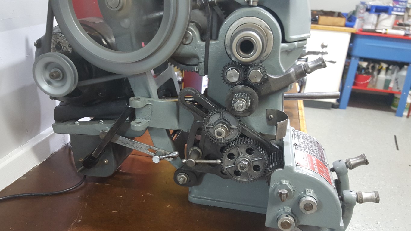
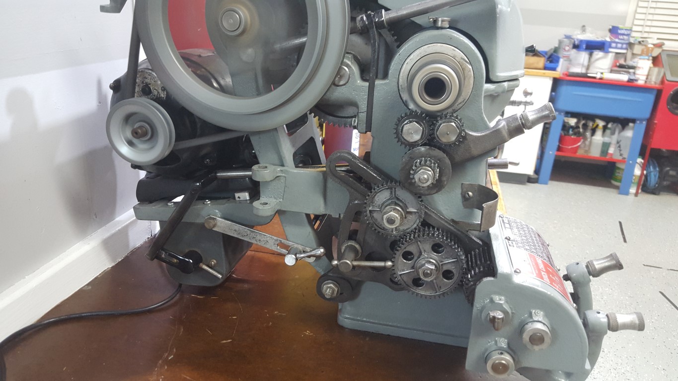
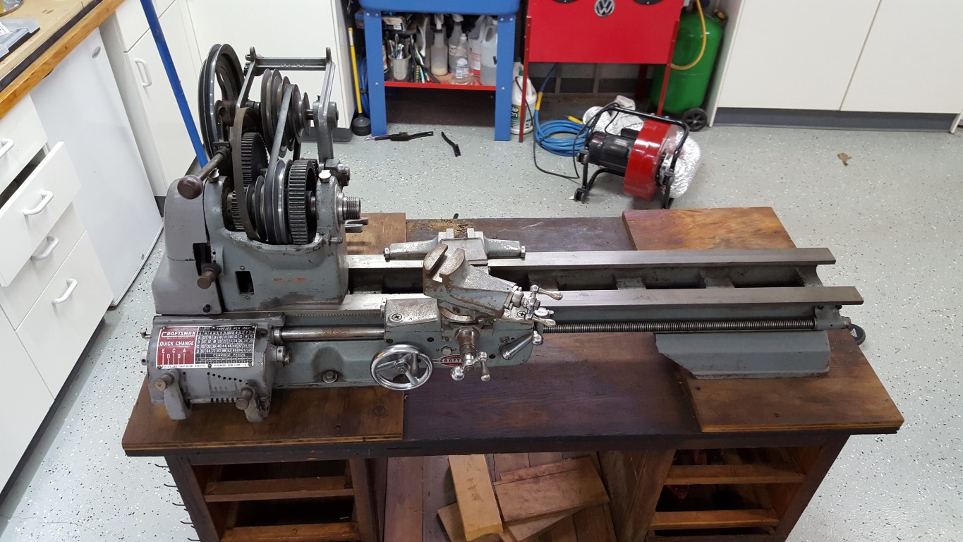
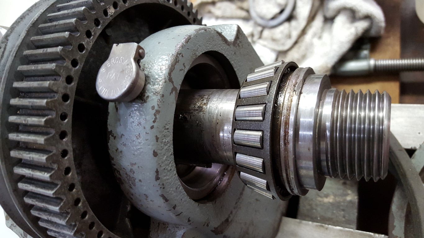
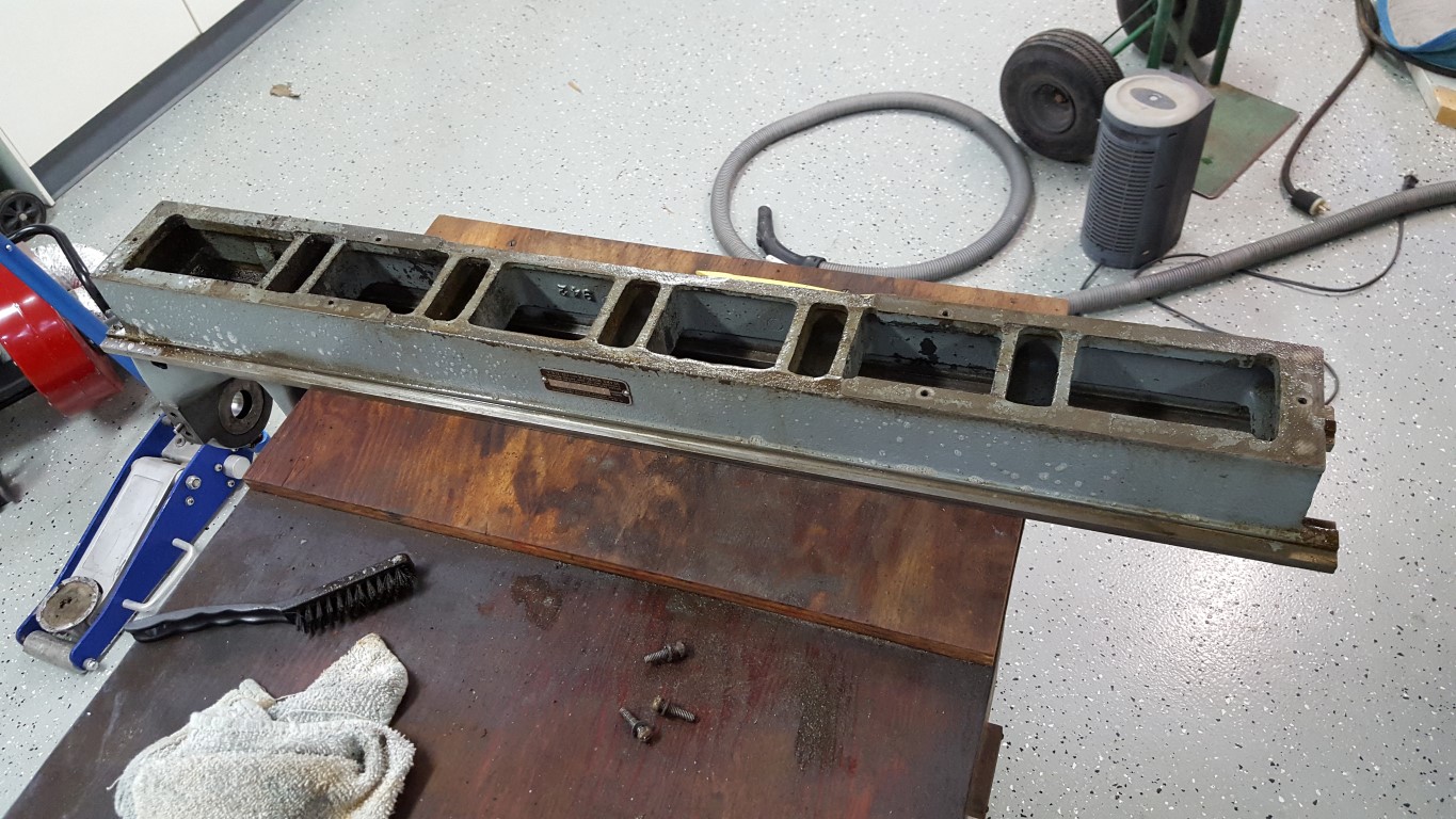
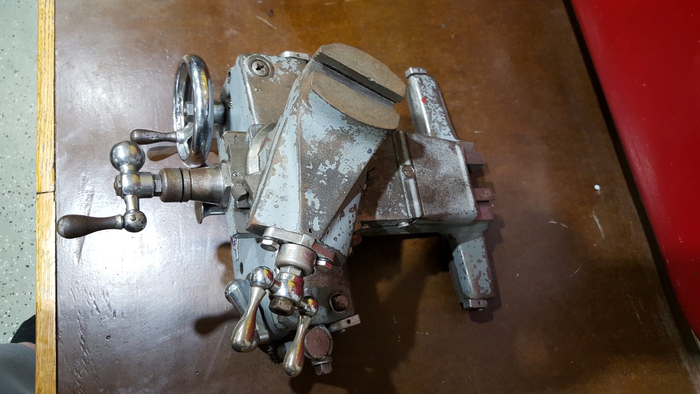
Atlas/Craftsman Metal Lathe
This winter I’ve done some much needed cleaning and painting of the garage; it’s survived the bus restoration and countless other small projects. This has put the jet engine project and bus transmission on hold, but I’m in no particular hurry with either.
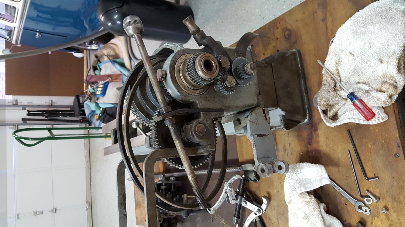
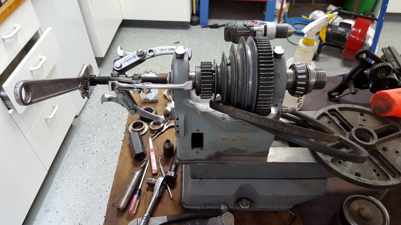
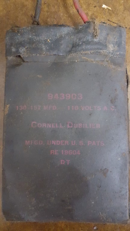
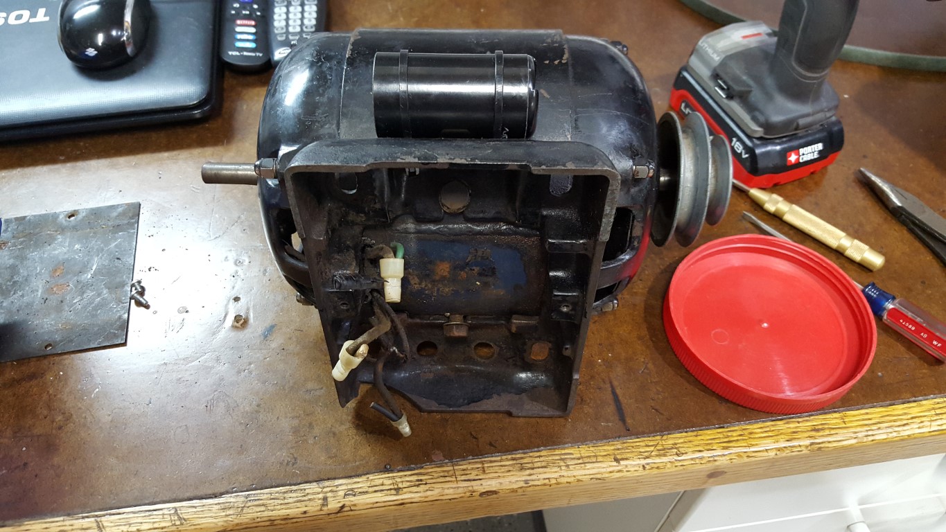
Also, recently I picked up an old Atlas (Craftsman) lathe I found on Craigslist with lots of tooling. This style of late was made by Atlas from the late 1930’s through the late 1950’s; based on the numbers engraved in this one’s bearings it seems to have been made around 1956. The manual that came with it was published in 1967; but I later found a receipt for the manual, proving that it was a replacement and explaining why the lathe in the manual looks like the late 1950’s through mid 1970’s version – both machines have all the same features and function the same though. For the most part it was in good shape and only needed some heavy cleaning, repainting, and a new motor capacitor; there are a few mechanical areas for repair/improvement that I will tackle, but nothing that prevents it from operating now. The original motor used a flat capacitor that’s no longer made in it’s motor base, so I had to get a little creative with mounting the replacement on the side of the motor.
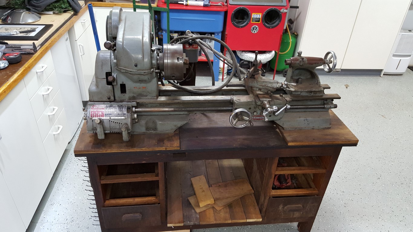


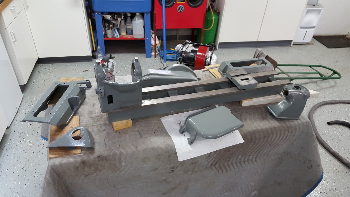
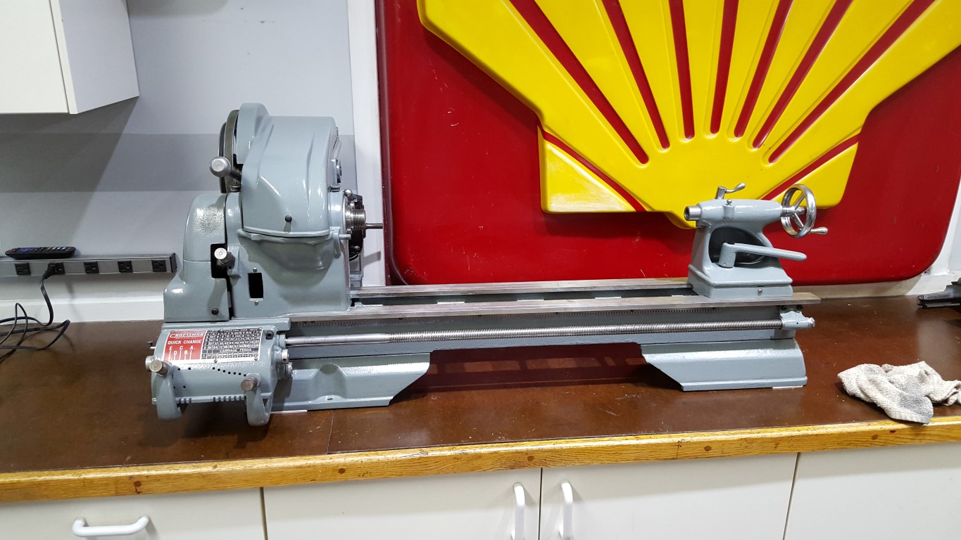
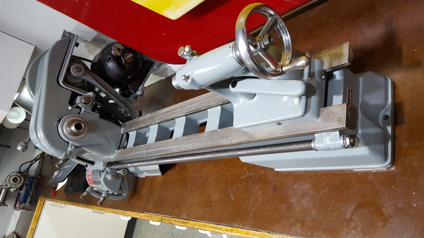
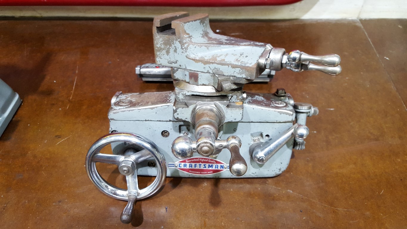
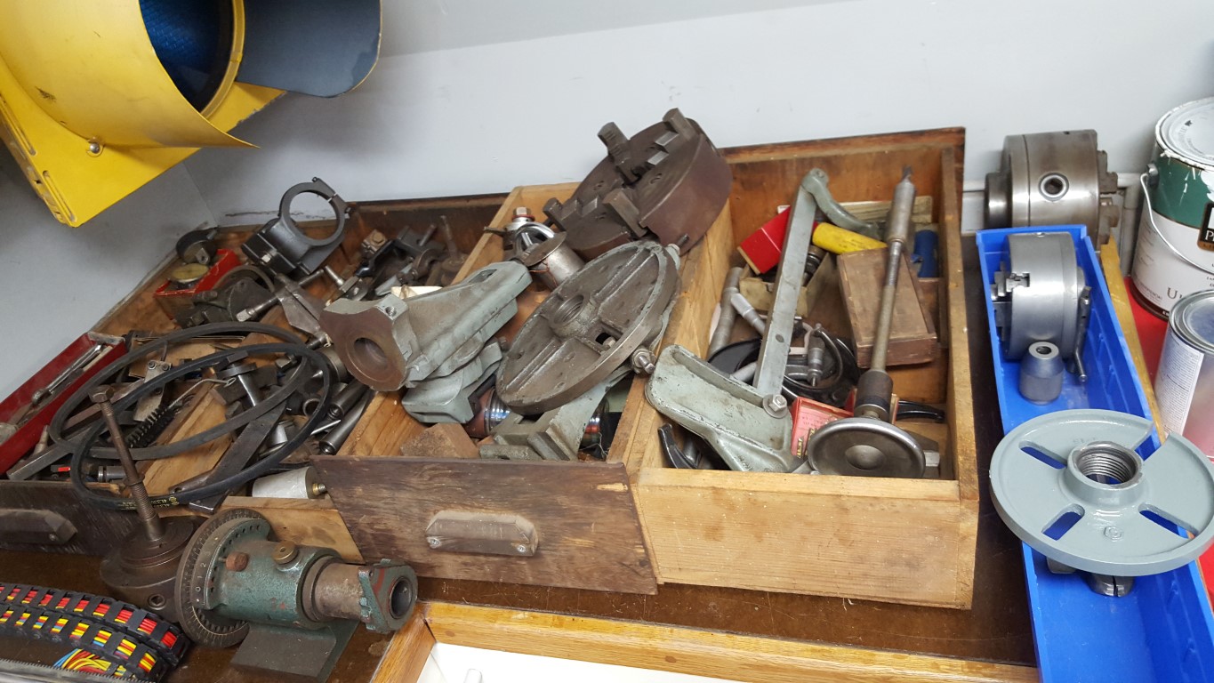
No particular project in mind for this, but no doubt it will come in handy with other projects especially since it has the milling attachment allowing it to serve as a small mill as well.
Hitch Anti-Rattle Device
There’s an inherent problem with the way that standard receiver hitches and accessories are built. No hitch manufacturer wants to build a hitch that’s too small for the average accessory (ball mount, bike rack, etc)., and no accessory manufacturer wants to build an accessory that’s too big for the average hitch. As a result, both manufacturers err on the side of caution and the result is a huge amount of slop on most hitch/accessory combinations. The result of this is a ‘clunk’ or rattle when turning with a trailer and, even worse, a magnification of the backlash at the top of bike racks, causing excessive swaying/looseness.
There are a number of ‘solutions’ to this problem. One of these solutions requires the accessory side to have threaded hitch pins, this is a no-go for bike racks (where the problem is the worst) since there aren’t any made this way. The other solution is a device that wedges between the hitch and accessory. This only works on one axis and would require extra tools/setup every time the accessory is connected/disconnected.
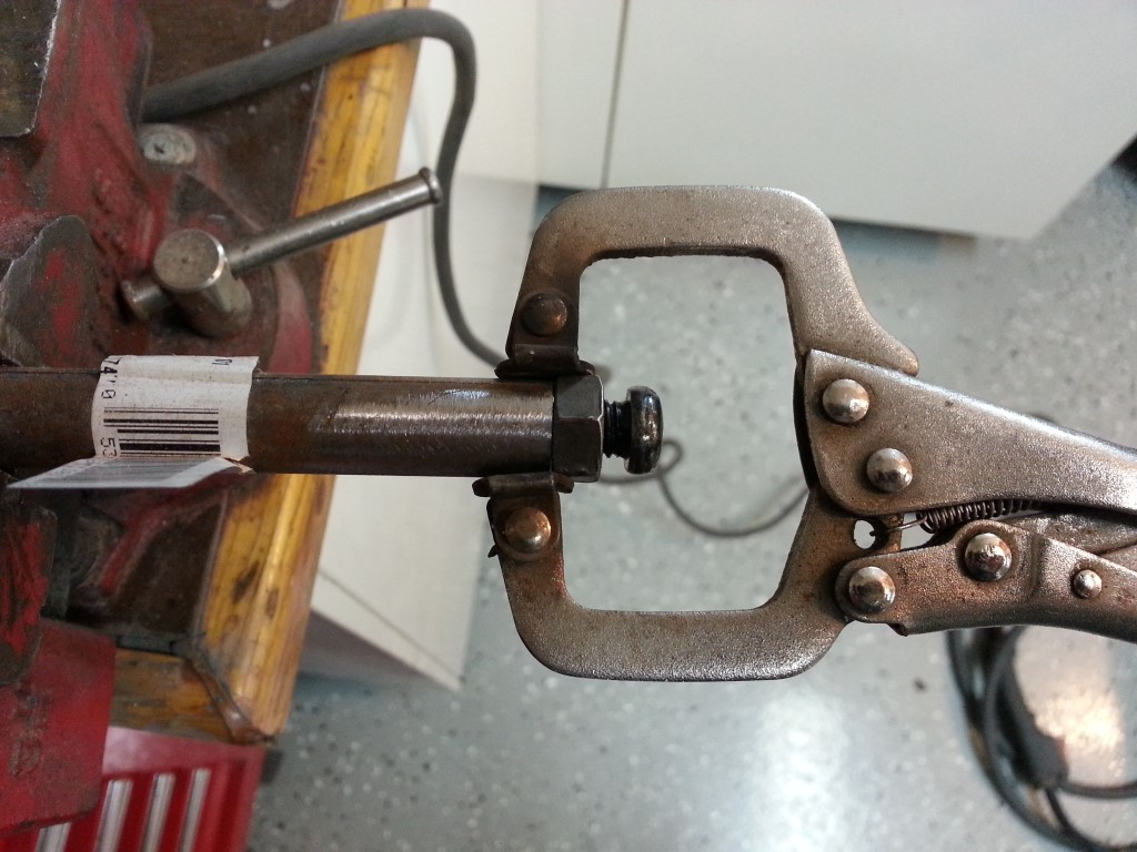
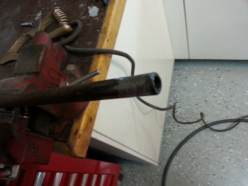
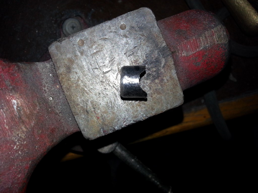
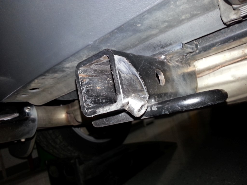
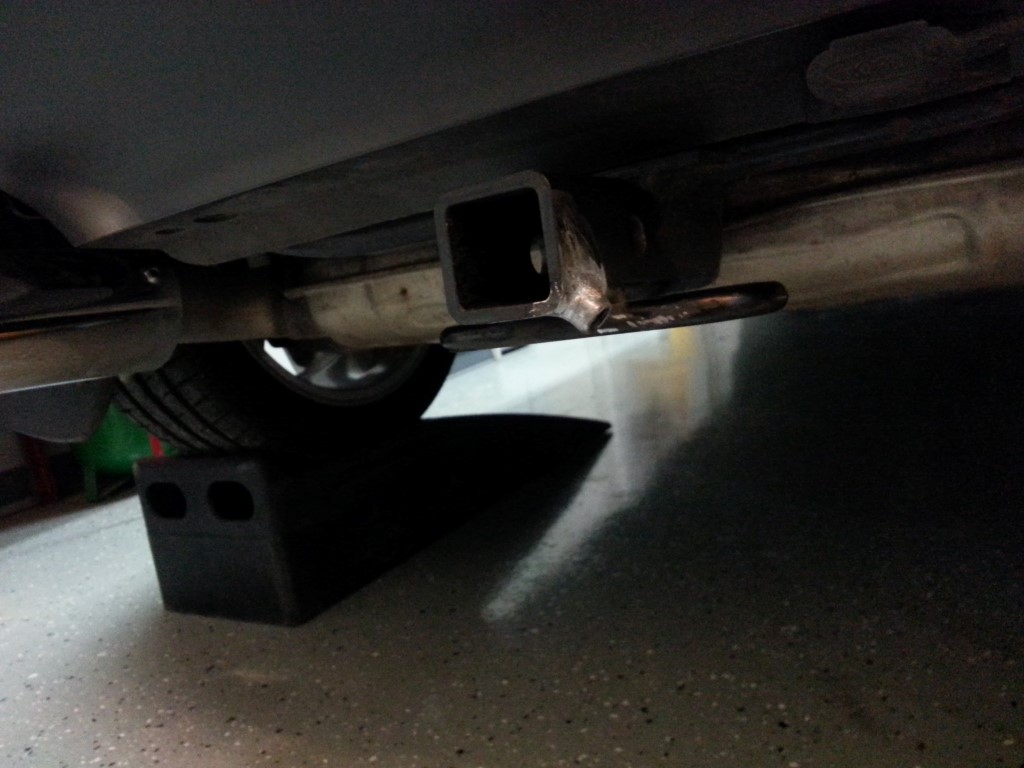
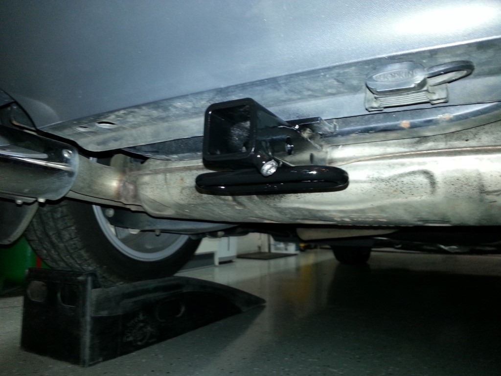
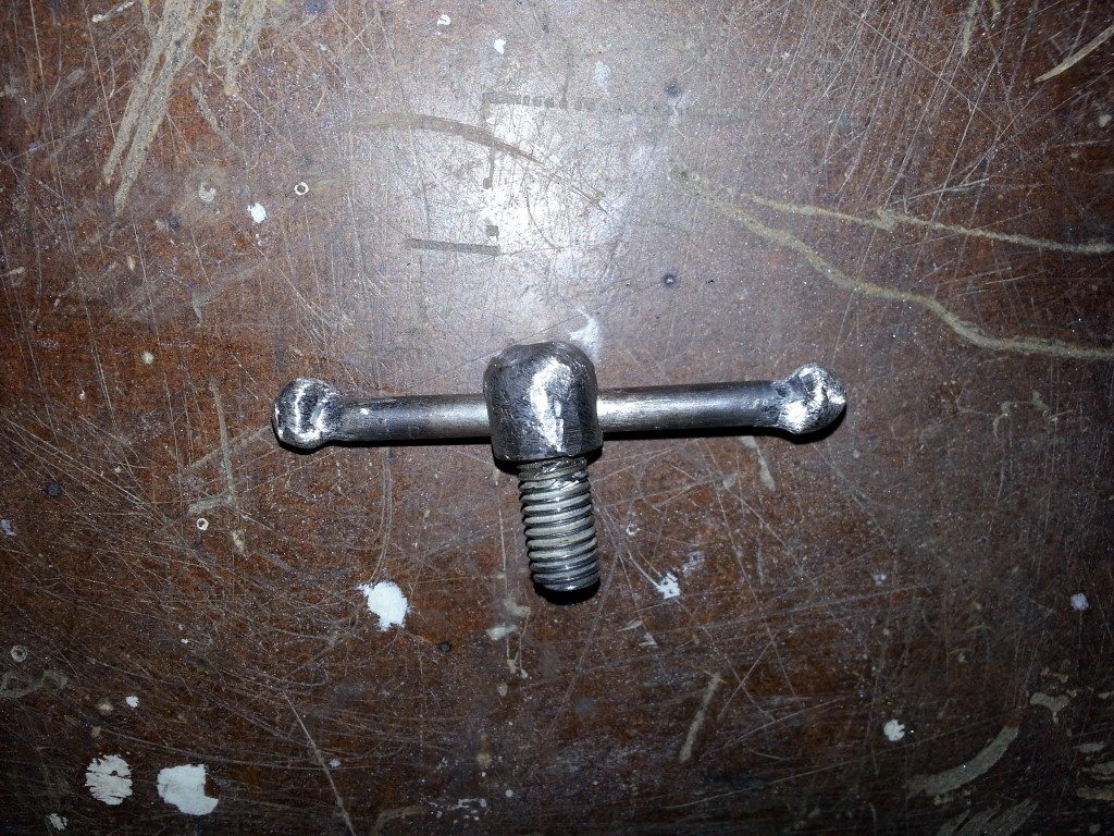
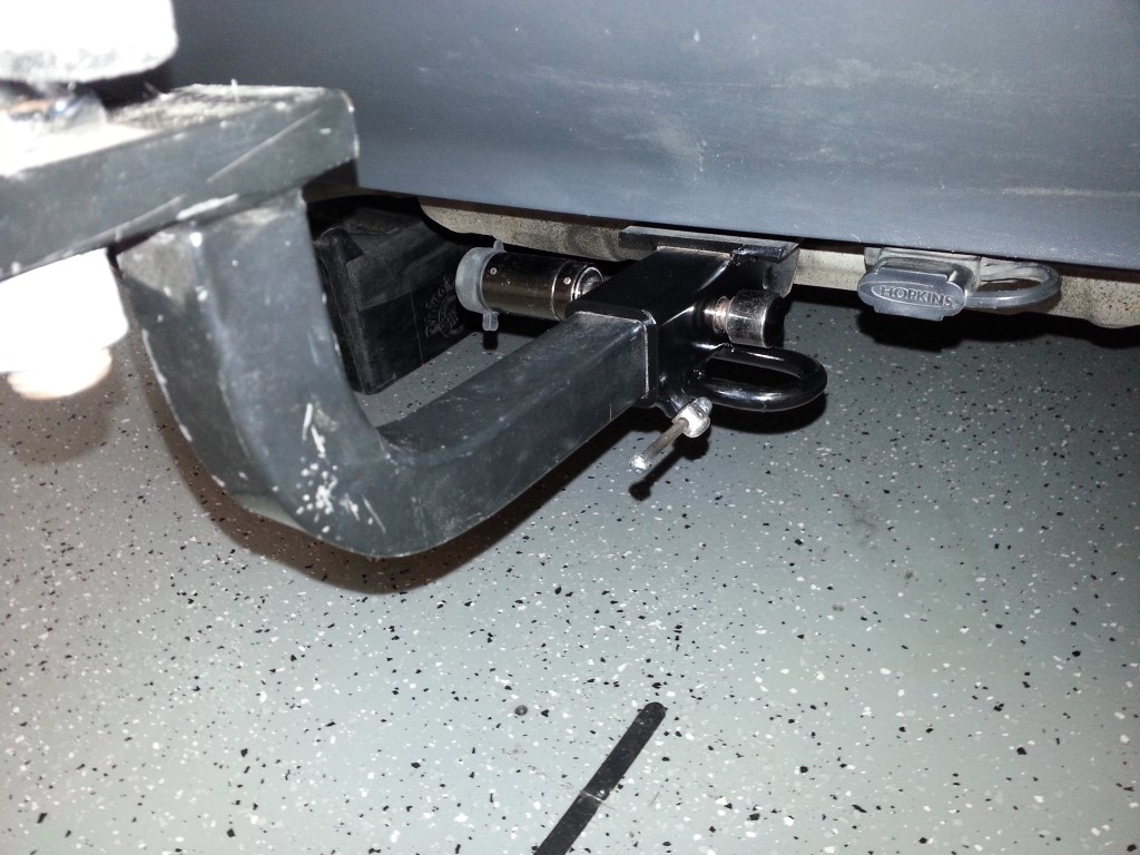
The alternative to this, which I’ve seen other examples of online, is to drill/tap a hole through one edge of the receiver so that a bolt can be used to push two of the flat sides of the accessory against two of the flat sides of the inside of the hitch. To get plenty of threads I went a step further and welded a nut (with small section of tube to fill the gaps) to the receiver. This also significantly reinforces the edge of the hole to negate any compromise in strength created by drilling the hole. This isn’t much of a concern though since most of the forces are transmitted through the hitch pin which is well in front of the new hole. For tool-less deployment and removal I fabricated a bolt with integrated handle, much like what’s found on bench vices. I eventually painted this bolt also, but it’s not shown in the pictures; I’ll leave this in the trunk when not used. The hitch rattle/clunk is now completely gone, plus it’s easy to deploy and will work for every hitch accessory.
Weekend Progress
Lots of activity this weekend:
#1 – Another coat of high build primer was applied and block sanded. Block sanding is very time consuming but I’m starting to see very good results. The pattern of colors that the primer/filler makes after sanding started off looking like a topographic map of the Himalayas; with each coat I can see it’s flattening out substantially.
#2 – The pop-out frames were glazed, sanded, and re-primed.
#3 – The black parts in the latest round of small parts (mostly sunroof parts) were painted black.
#4 – The low spots on the body got yet another coat of high build primer after #1.
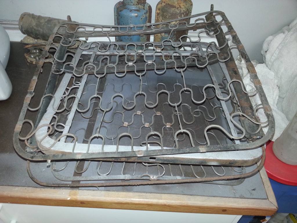
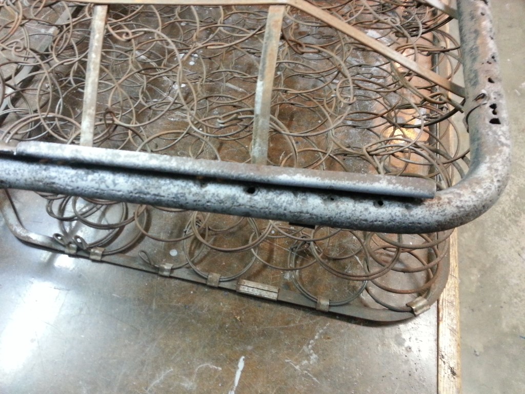
#5 – The seat frames were partially sandblasted, but the effort was cut short since the blaster kept clogging. I rebuilt the blaster and it should perform much better on the next rain-free blasting opportunity.
#6 – Holes in the drivers side front lower seat frame were welded shut. I forgot to take pictures after the welds were ground down, but it turned out very nicely.
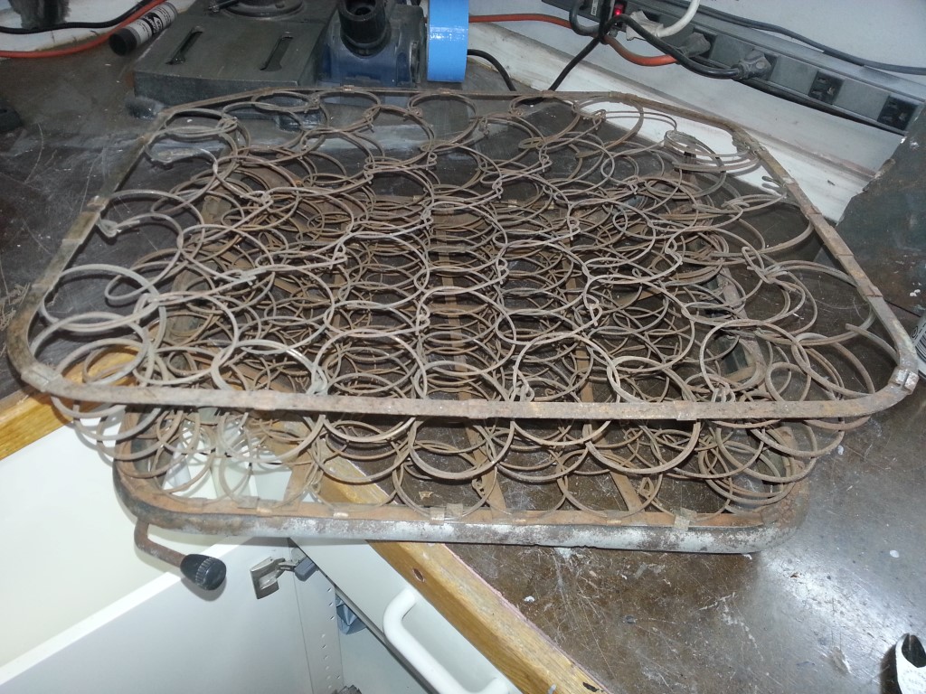
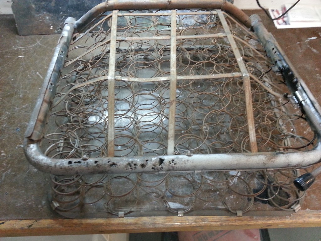
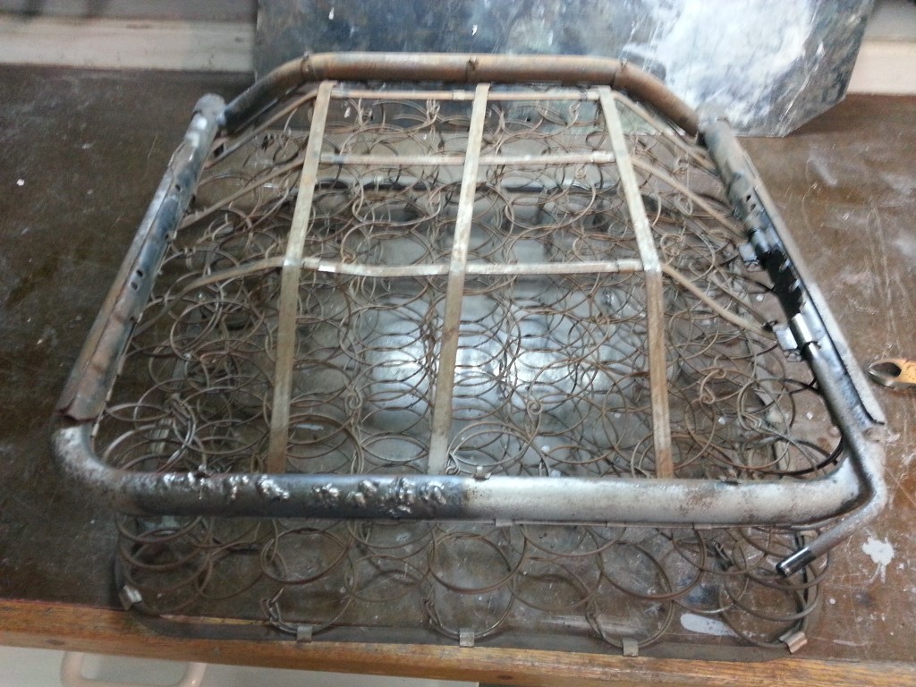

The search continues for the elusive passenger side front lower seat frame. This seat is specific to the optional ‘walk-through’ configuration that this bus has. Although the ‘walk-through’ option was heavily advertised it was expensive, so the minority of buses were built this way. This problem is compounded that through the years, especially during the 1970’s custom van craze, many of the walk-throughs had their bulkheads cut (mine included, but fixed) to install swiveling seats. When the swiveling seats were installed in all these buses the original seats were lost forever, though I’m not sure why they kept the passenger side seat back without the base.
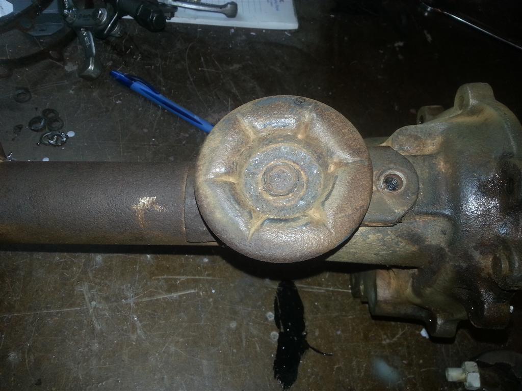
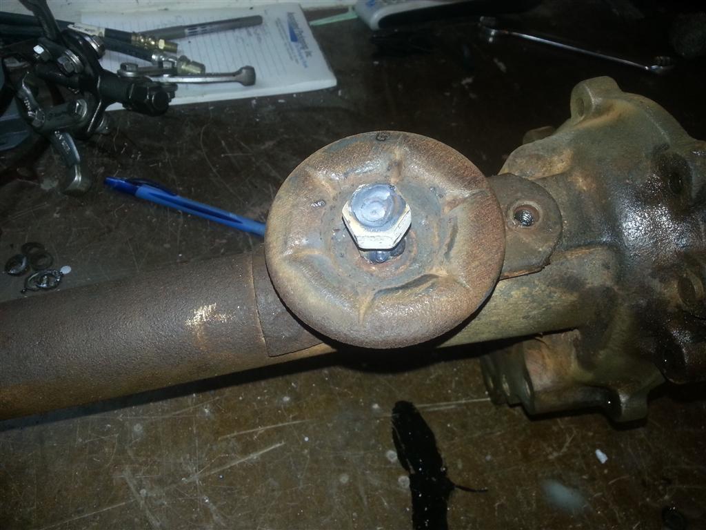
Axle Bumpstop Perch Repaired
The perchs on the rear axle that holds the rubber bumpstop have what can only be described as a design flaw in that they hold water with no way for it to drain. Under these conditions it’s not surprising that the center post rusted away from the center of one. I welded on a nut and bolt of similar diameter in place of the missing post and drilled small drain holes at the bottom of both perches. The rubber bumpstops slide over the top of the posts so the repair will not be evident and will work as well or better than original.