CNC Lake Coffee Table
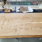
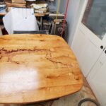
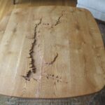
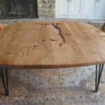
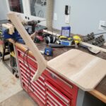
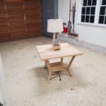
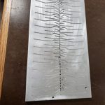
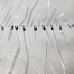
Continuing with the first batch of wood from the sawmill and along with the other furniture changes it sparked the idea to make a new coffee table. The previous table had been passed-on from the previous owner of the previous house, nothing special about it, overdue for replacement. There’s a nearby lake I wanted to incorporate into the design, and by far the toughest part of this project became obtaining its bathymetric data. The entity that controls the lake was helpful with a records request but ultimately their best data was a medium resolution plot, shared via pdf. There were some hints from various navigation and fishing apps that better data might be out there, but after a lot of messing around with importing and converting this turned into a dead end. I eventually resorted to sending the pdf provided by the govt through an image vector tracing tool, followed by many hours of manual cleanup. This gave a single contiguous vector curve for each depth increment that I could then assign to a CNC machining operation.
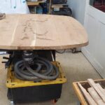
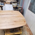
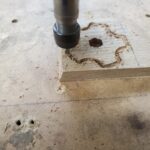
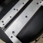
I tested the CNC programming on a scrap piece of plywood before sending the oak slab through. The table is the full 4ft width of the CNC but wider than the CNC’s depth. To get around this problem I ran the carving on the middle section of the table before completing the full slab glue-up. When the full slab was together I traced the large radii using a yardstick as a compass and connected these with smaller corner radii. This outline was cut with a jigsaw before being belt sanded and rounded over with the router. Then final sanding and finishing. I cut two small sections of steel angle and secured them to the bottom of the table across the slab joints with screws in slotted holes. This will help hold the table flat while still allowing some seasonal wood movement. Last step was attaching some off-the-shelf hairpin type legs.
Side Table and Lamp
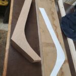
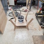
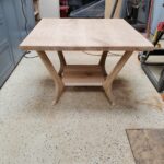
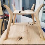
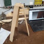
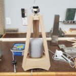
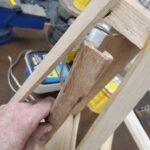
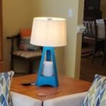
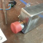
The first batch of wood from the sawmill was getting dry enough for use and we were planning to replace the den sofas; to go along with this change a side table would be needed. At the same time I also created a lamp that would house a smart speaker and act as a cover for the phone charging cable from below. A key consideration for this project was cable management – for the table, a 3-conductor cable is routed through the leg, allowing a power strip to be mounted under the table. The power strip has a phone charger, power to the lamp, and power for the smart speaker which all route up through the center of the table, hidden by the lamp. The lamp cord is also hidden within one of the lamp supports. A knob was cut on the CNC router to secure the lamp shade.
Generator Install
After fixing the generator last year (this project) I needed to install it permanently. I pulled the permit last year and it expires soon, so lately I’ve put more work into this to get it done. After a year of on-and-off work it’s finally ready for inspection. Permanent installation consists of 3 main parts: mounting the generator, installing an interlock, and running cable from the generator to the house electrical panel.
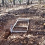
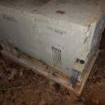
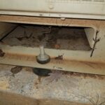
#1 – Mounting the generator was relatively easy – I dug out a flat area, made a form, added rebar, and poured concrete. The only tricky part here was keeping the threaded bolts positioned correctly so that they’d line up with the generator mounting holes. After the concrete cured I moved the generator in place and bolted it down, using hockey pucks as vibration dampers. I turned down the upper hockey pucks on the lathe and machined a step into them so that it keeps the generator centered on the mounting bolts.
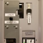
#2 – The interlock requirement is the most important part of any generator installation since it prevents energy from the generator back-feeding into the utility, which would create a dangerous situation for the linemen that are working to restore power. There are several ways to accomplish the interlock:
– Automatic Transfer Switch: This switch is placed inline between the meter and main panel, during an outage it automatically disconnects the house from the utility, connects to the generator, and sends a signal to start the generator. This capability would be nice but there’s a lot of complexity, expense, and extra work involved.
– Manual Transfer Switch: This switch is placed inline between the meter and main panel and you can manually select which power source the house is using. This is much simpler than the automatic switch, but still requires an additional small panel for the switch.
– Main Breaker Interlock: This is a sliding plate that mounts inside the existing main panel and it prevents the main breaker from being ON at the same time as another nearby breaker (and vice versa). The generator powers the main panel through the nearby breaker.
I opted for the Main Breaker Interlock since it’s allowed where I live and it’s the simplest way.
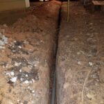
#3 – Running cable was the toughest part. Since the generator isn’t a residential unit that’s fire-rated to be directly next to the house (it probably would perform better than a residential unit, but the military doesn’t do the residential testing) it had to be at least 2ft away. 2ft away would have made for an awkward placement and it would have been in the way a lot, so instead I took it much farther out near the tree-line; leading to a ~60ft long trench. Code requires either 18″ of cover or 24″ of cover depending upon whether or not conduit is used. I opted to use conduit since the shallower trench saved digging effort and also reduced the chance of encountering any other utilities in the process. Most of the digging was through very dense/hard clay and it was slow-going with a trenching shovel. I welded the shovel back together at least a few times. I also experimented digging with the pressure washer, which mostly made a mess. The last 2ft near the house were through concrete; the technique I used for this was to turn the area into Swiss cheese with a hammer drill, break it out with a small air chisel, and then progress down to the next layer. I had been on and off of this effort over the past year and finally finished this weekend.
(#4) Misc things. Since the generator wasn’t originally intended for residential installation there were a few extra things I did to convert it:
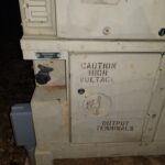
– I added cabinet locks to all of the access doors. This isn’t for security so much as it is to prevent anyone that shouldn’t be in there from getting into danger, especially the front door that has the output terminals directly behind it.
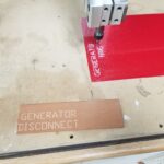
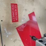
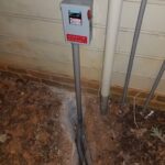
– One of the code requirements is that there must be a way to disconnect the generator outdoors. The generator itself sort-of/kind-of meets this requirement since it has a switch on the operator panel that will open the relay that connects the output power. Since this switch isn’t directly a disconnect though and since there’s a lock on the operator panel that could restrict access I also added a ‘real’ disconnect on the exterior of the house. I used the CNC router to make an engraved sign to mark it.
– Since the interlock completely disconnects the house from the utility it can be tough to know when power is restored. Electrically it would be possible to have a light/buzzer on the utility connections before the main, but since this wouldn’t have a breaker it wouldn’t be safe or code compliant. I found a device that’s made exactly for this problem and installed it. It has it’s own power via a 9V battery and has an antenna that wraps around the line from the utility to monitor power status. The alarm is armed manually when on generator power and as soon as utility power returns its siren sounds.
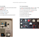
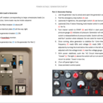
– I made a step-by-step instruction list with photos so anyone that’s home at the time of a power outage can start the generator and operate the interlock. This list and the key to the generator are held inside the main panel with magnets.
Next step is to get it inspected and then I can backfill the trench and clean the mud off of everything one last time.
Checkride Passed!
I haven’t updated in quite some time; summer was very busy with work, travel, and the occasional practice flight. I documented a number of these things with the intention to later post, however I failed logging into my phone one too many times and it deleted all photos.
Bus: Only minor work done on the bus, mainly more wet-sanding & polishing.
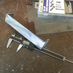
CNC: I created a homemade drag knife for cutting out vinyl/cardboard/paper. This is still a work in progress as are accuracy refinements and fine tuning.
Aviation: I passed the Private Pilot check ride! This generally means I can now fly any single engine land airplane (that does not require a Complex, Hi Performance, or tail-wheel endorsement) to/from any airport (besides the obvious: military/etc); and I can now carry passengers that aren’t flight instructors. I should be getting the official plastic certificate (There’s no such thing as a “Pilot’s License”) card in the next few weeks like the one below.
 In practice, switching to something other than a Cessna 172 would require a little bit of transition training and there are time limitations to renting the trainer plane. So not sure what’s next with this hobby, but there’s a lot to learn and it’s still very interesting…
CNC Machine: All axes working
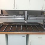
Tonight I got the machine fully assembled and working with all axes (and the spindle) at once. This greatly improves image plotting since the pen can be lifted. I just need to mount the spoil board and I should be able to begin cutting tests.
CNC Machine: Plotting Images
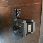
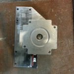
It’s been a while since I’ve updated, and I’ve gotten a lot done during this time. I modified the gantry motor plate (one of them at least) to include a spring tensioner and also added some diagonal braces to the gantry columns; the gantry now runs even smoother and with little or no backlash. I then added the Y axis guides, fabricated the Y axis motor carrier and Y rack support. Once I got all the Y parts together I was able, for the first time, to test coordinated motion between axes by clamping a pen to the Y axis. The results of this testing were great. It drew very accurately with the pen, the drawing path even occasionally required overlapping the same pen line later in the program; it was able to follow the existing lines exactly. The only thing it couldn’t do was lift the pen, since the Z axis wasn’t installed…
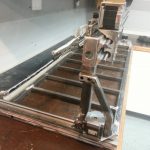
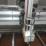
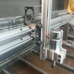
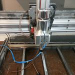
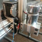
…So after I eventually finished playing with plotting images I began work on the Z axis. The biggest challenge with this was attachment of the spindle mount; the spindle mount is one of the few metal things (other than the motors/guides/racks) that I didn’t fabricate from scratch; despite this I still needed to do some fairly extensive machining/modification to get it attached to the Z extrusion in a very secure but still adjustable way. With the spindle mounted to the Z extrusion the remainder of the work was just some minor drilling, tapping, and cutting. The Z rack is a lot longer than it needs to be for the amount of travel Z has; it was the last rack section to get cut so the extra length is just the leftover/spare, it fits on the extrusion so no sense cutting it off.
Sometime during initial gantry testing I fried the Z axis motor driver on the smoothieboard when moving the gantry by hand with the drivers off. Z wasn’t even connected during this but my guess is the spinning gantry motors fed back through their drivers onto the supply bus; Z happened to be the weakest and it fried with a snap & flash. Because of this I was actually testing the Z axis with the Y driver. I have an external stepper driver on the way and once it arrives I should be able to move all axes at once and really see what it’s capable of. Next Steps:
#1 – Finish electrical enclosure fabrication
#2 – Modify other gantry motor plate to include spring tensioner
#3 – Final fabrication of cable management, cosmetic covers, etc.
#4 – Disassemble, body work, prime, paint
#5 – Final reassembly & wiring
CNC Machine: Gantry Moving
Lots of fabrication work over the past week including the motor brackets, columns, and home switch trigger. The gantry axis (still debating whether to call this X or Y) guide rails as well as many other parts arrived Friday and were mounted to the machine base. The machine base also got a coat of body filler (the pink spots in the photos) and sanding in anticipation of paint.
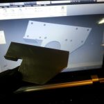
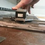
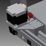
With everything fabricated and assembled, I was able to temporarily wire the system and run the first motion tests of the gantry. Overall I was extremely impressed, the homing switch worked and both sides stayed perfectly in-sync. The gantry achieved the same 1200IPM I had seen in the rack testing. I somehow managed to build it with tight enough tolerances that the rack doesn’t bind and isn’t overly loose over the full travel range, but there are still some noticeable differences in some spots. Right now the mesh is only adjustable with the play in the motor mount screws. One improvement I’ve already got on the drawing board (screenshot below) is to add a spring tensioner system to keep the rack mesh constant across the entire travel. There was enough room where I won’t have to re-build anything to do this, it almost looks like I planned to have it from the start.
Also, in aviation news, this weekend I passed the phase check to be able to fly solo cross-country. I’ve been able to fly solo for a while but only within the local airport area; this now means I can fly solo between airports and continue practicing cross-country flying.
CNC Machine: Frame Progress
This weekend I did more work on the CNC machine base:
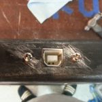
– Power inlet, power switch, USB port, and E-Stop holes were all drilled & filed to the correct shapes.
– Rack support rails were added to the frame edges and end-caps added to the frame front and gantry ends.
– Flame straightened the frame to relieve welding stress/distortion. It was my first time trying this so I wasn’t sure about it at first, but it worked great. I put a straightedge on the frame and found which side was convex; then heated that side in several places until it was just red hot. After it cooled the straight edge showed a much smaller gap in the middle on the concave side; I repeated this until the frame was flat in all directions.
– Flame straightening got the frame flat overall, but there were still a few high-spots. These were ground down with a flap wheel until no gaps existed with the straight-edge and the entire frame was perfectly flat.
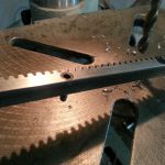
– Machined holes into the gantry drive racks. The clearance between rack edge and the inside edge of the rack teeth was extremely close. I bought some extra room by grinding down the outside diameter of the bolts some, but it was still very close. For the most part I was able to get the holes centered exactly in in this small space, but there were a few holes that created a notch in the outside edge of the rack; luckily none of the holes interfered with the rack teeth. The other racks will be easier since they’ll be mounted from the back side with partial depth holes drilled/tapped into the back.
There’s still some fabrication work left to do, but several critical parts (Guides, spindle, etc.) are all on a slow boat from various far east locales. They’ll become the limiting factor, so I’m taking it slow and making sure everything is done as well as it can be.
CNC Machine Fabrication Begins
The metal has arrived and over the last few nights I’ve begun fabrication of the machine. For the electronics enclosure I’m re-purposing the original crumpled hood that came with the golf restoration project. After removing the inner support, the outer hood skin was a reasonably flat piece of sheet metal. (That does also make this machine part VW, but it wasn’t intentional) I don’t have a big press brake for accurate bends, so the box that resulted is a little wonky, but its nothing that can’t be salvaged with some body filler and sanding.
I’m moving fairly slowly with the machine base, making sure everything is as square, flat, and true to the design as my ability to measure, and so far it’s looking really good. I also have the gantry mostly fabricated, which consists of two pieces of angle iron welded edge-to-edge, forming a channel.
Remaining:
– Fabricate gantry columns
– Fabricate motor plates
– Fabricate Z axis mounting plate
– Fabricate electrical enclosure lid & connect to base w/ piano hinge
– Machine base flatness check and hand scraping of guide mounting ways
– Drill & tap holes (dozens of them) in the machine base and racks for mounting the racks and guides
– Assemble/Wire/Test
– Disassemble, Paint, & Reassemble


