I got the idea for the monitor lift from an example online using all-thread as lead screws to drive a platform. Essentially I’m just replicating this idea but with a few tweaks that take advantage of having the lathe to make it better/stronger, easier to build, and to take advantage of spare parts I already had.
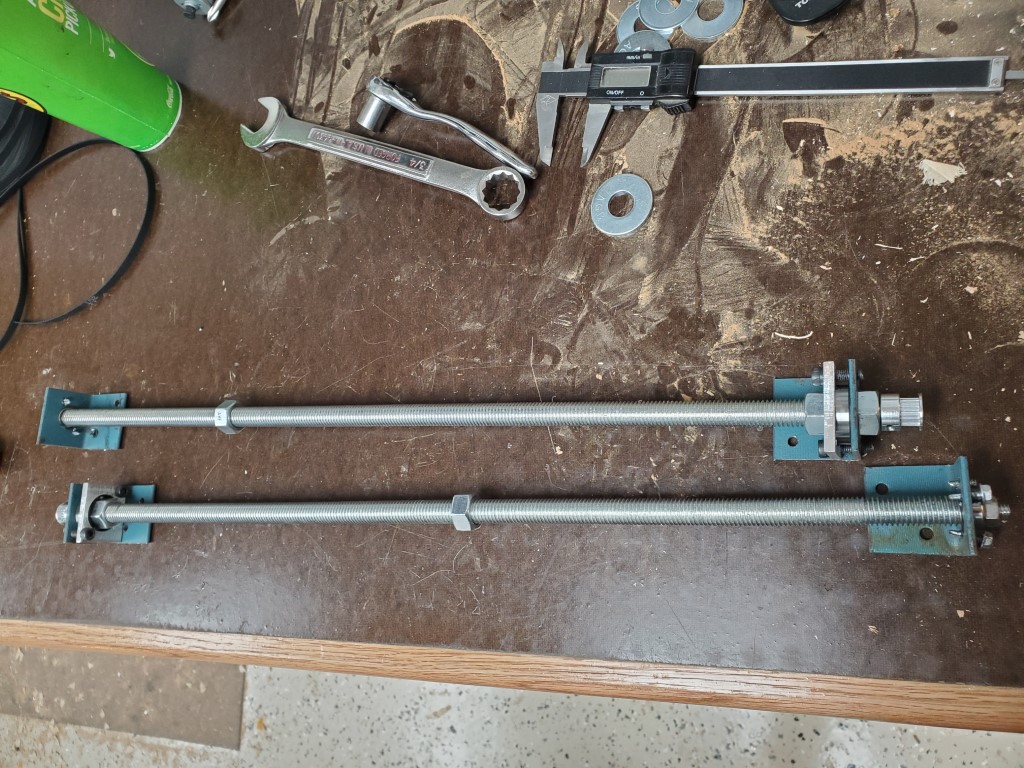
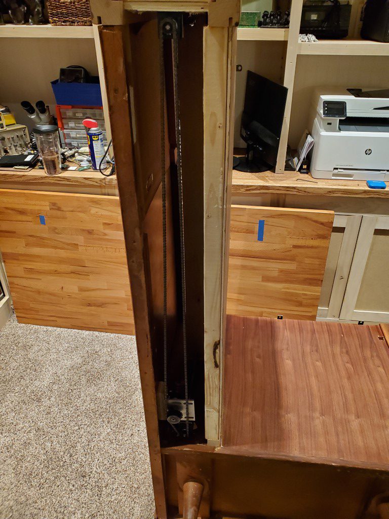
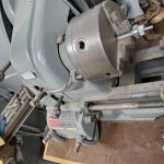
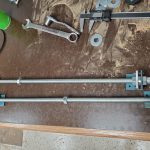
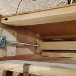
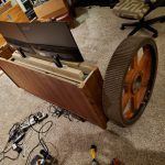
First I cut the all-thread rod to length and then I turned down one end of each to fit the inside diameter of some spare bearings. I left an extra bit on the end and turned it down to fit the inside diameter of a timing belt drive sprocket – this was later replaced with a chain sprocket due to slipping. I repeated the same on the top side of each rod (without the extra bit for the drive sprocket) and then I cut some metal brackets to hold the outer bearings. I then cut a small platform and attached two nuts to it that would connect it to the threaded rods.
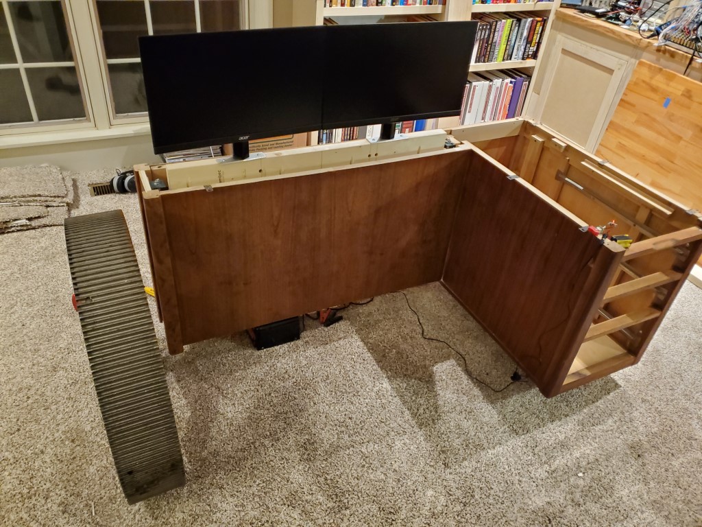
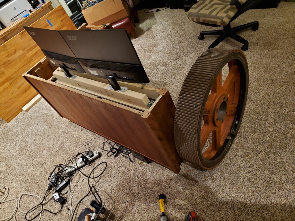
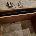
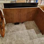
These parts were all assembled into the desk; a few small shims were needed to get the rods exactly parallel. I then connected the threaded rods together with a small #25 chain drive. To power the lift I tried a few different test motors and eventually settled on the guts from a small/cheap electric screwdriver – this provided enough torque while not requiring a huge power supply. It could be a bit faster and I need to add some sound damping, but it’s working very well for an initial attempt.
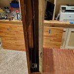

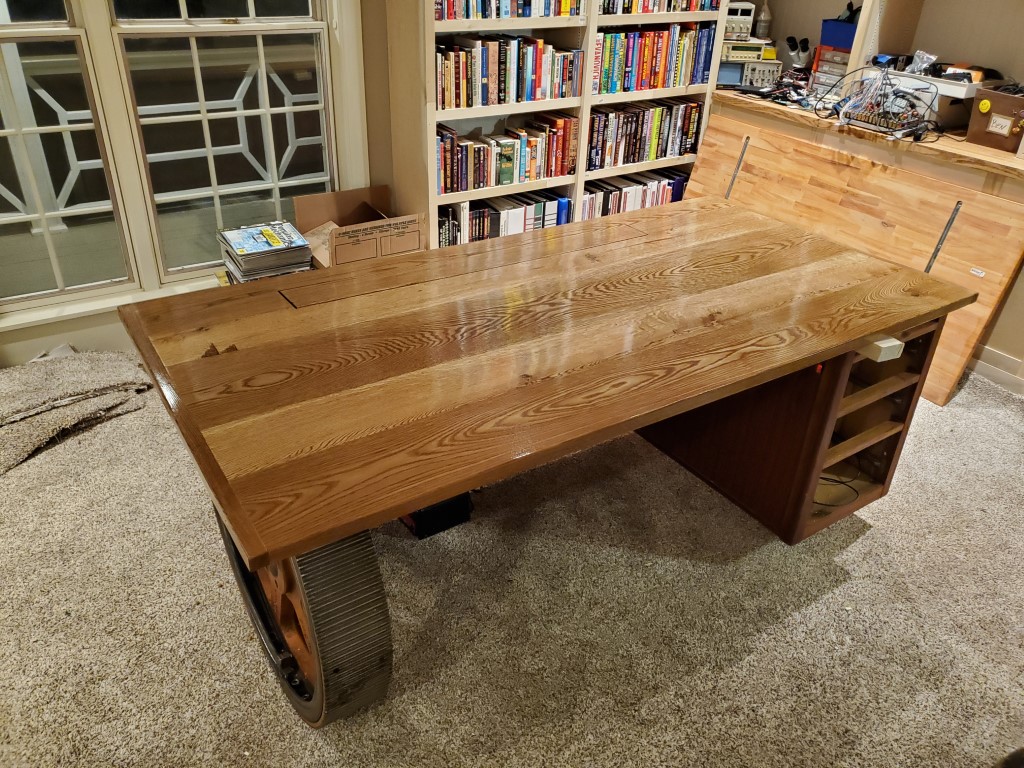
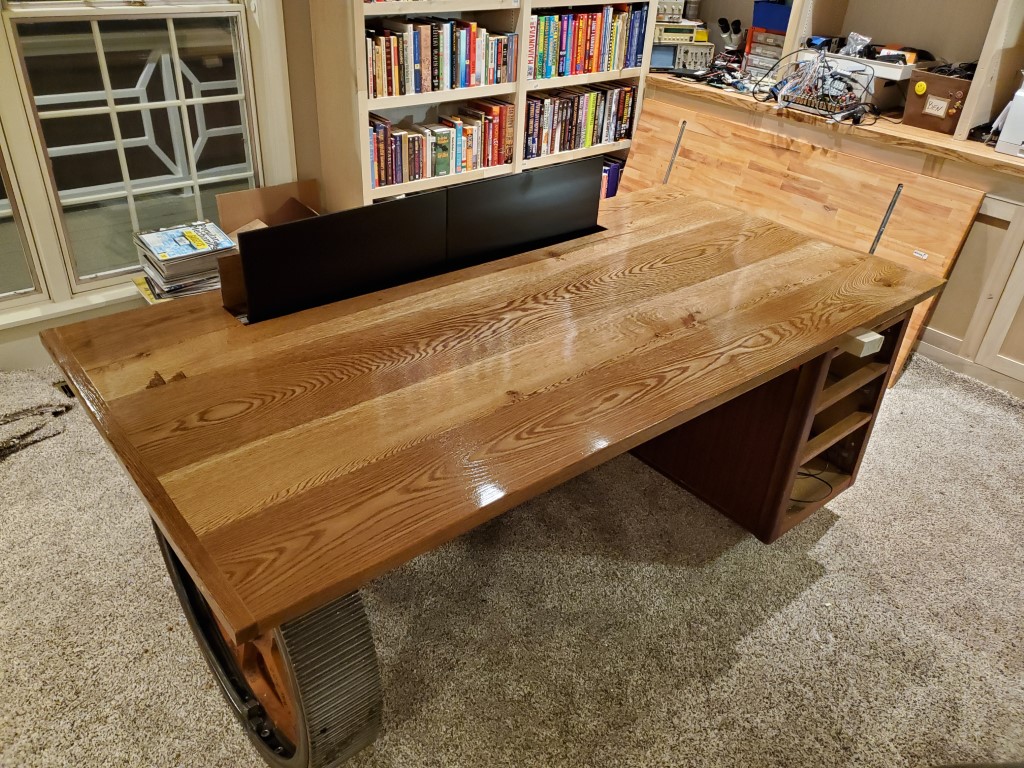
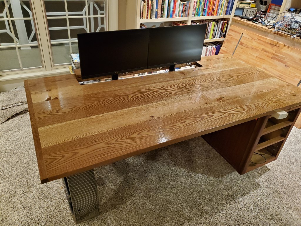
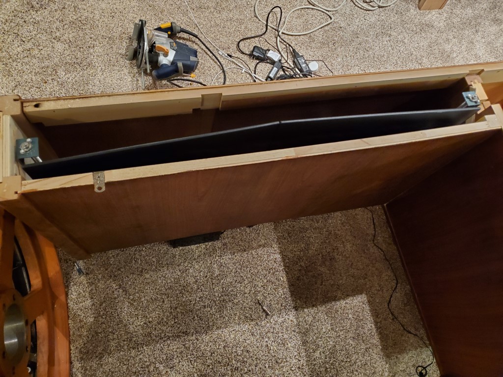
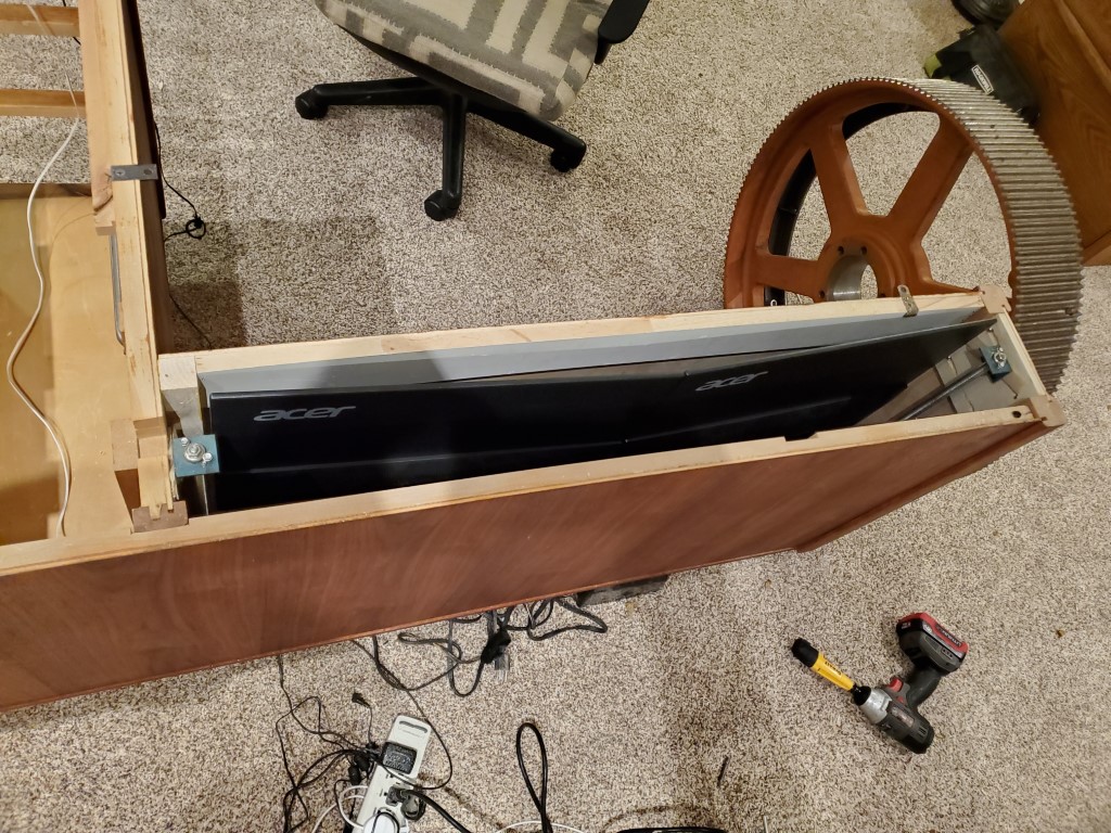
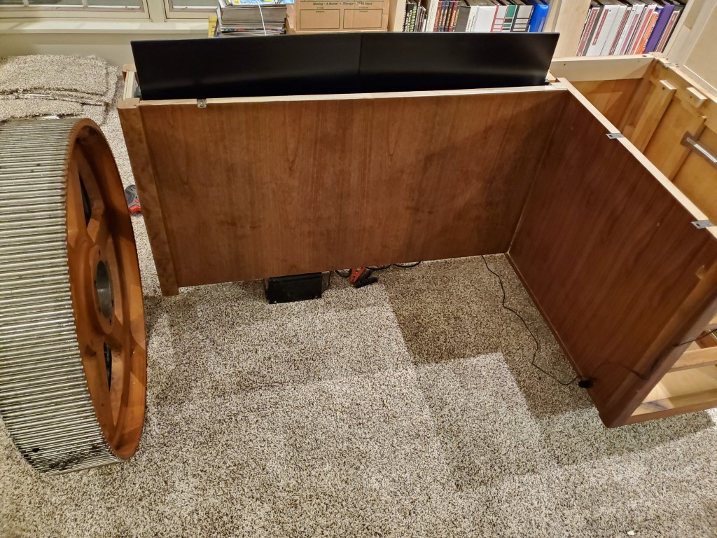
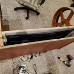
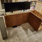
I also made some mounting plates to adapt the monitors to a fixed mounting since the regular bases were too wide. The monitors were then mounted to a 2×4 that acts as a spacer and also adds strength to the platform. Once the tabletop is in place the 2×4 and the rest of the mechanism will not be visible since the monitors will rise so that their bases are just flush with the top – I’ll likely add a trim piece to block this off. The monitors also drop low enough that the table top will clear with no problems.
The last step was adding limit switches and rewiring – moving the toggle switch up runs the lift up until the positive switch is tripped, and moving the switch down runs the lift down until the lower limit switch is tripped.
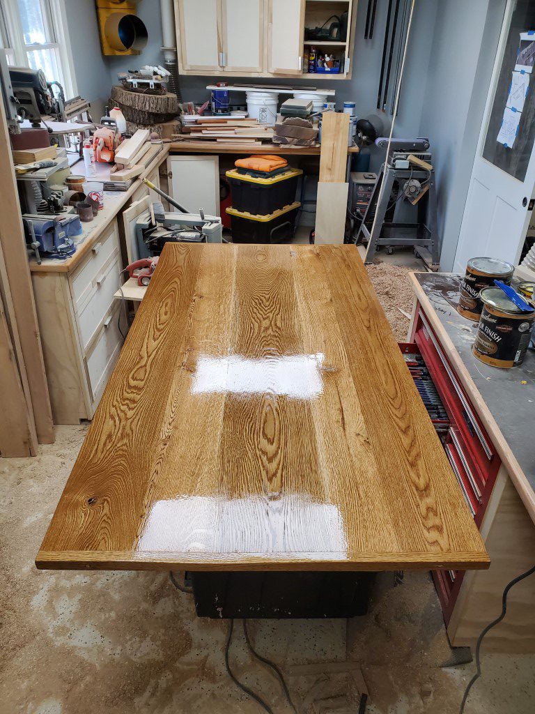
Next up will be making the tabletop…