After fixing the generator last year (this project) I needed to install it permanently. I pulled the permit last year and it expires soon, so lately I’ve put more work into this to get it done. After a year of on-and-off work it’s finally ready for inspection. Permanent installation consists of 3 main parts: mounting the generator, installing an interlock, and running cable from the generator to the house electrical panel.
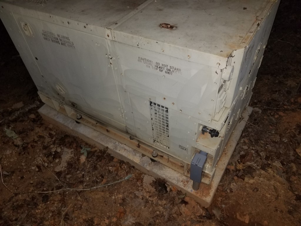
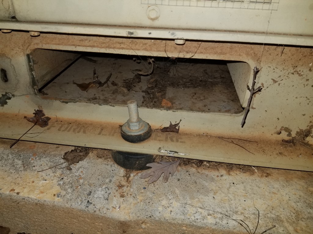
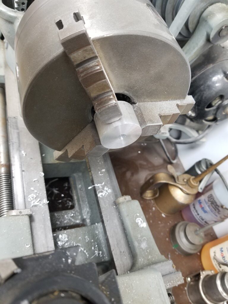
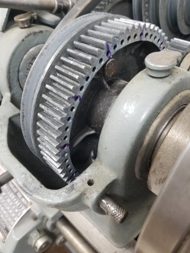
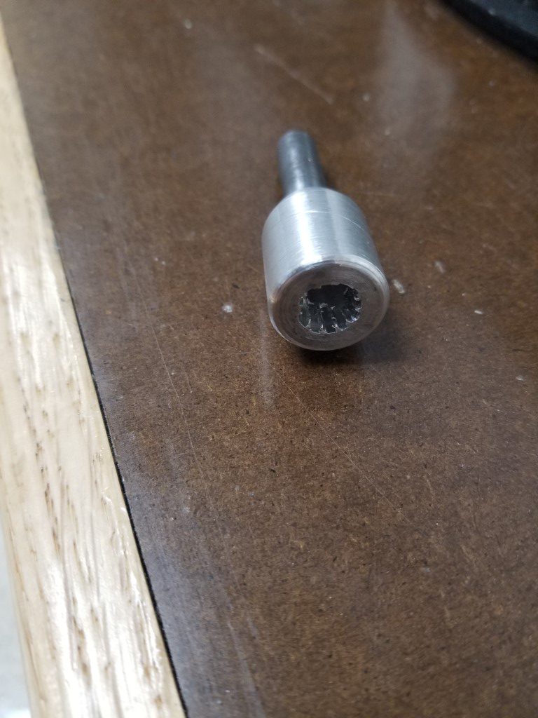
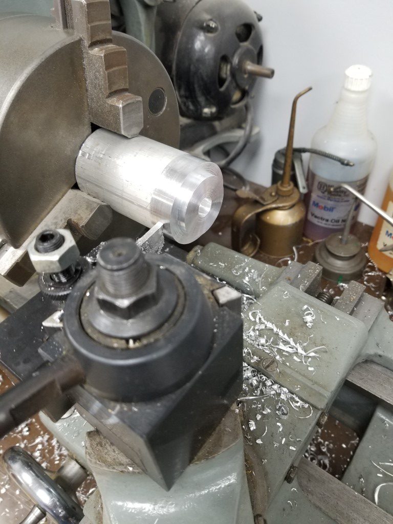
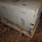
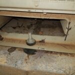
#1 – Mounting the generator was relatively easy – I dug out a flat area, made a form, added rebar, and poured concrete. The only tricky part here was keeping the threaded bolts positioned correctly so that they’d line up with the generator mounting holes. After the concrete cured I moved the generator in place and bolted it down, using hockey pucks as vibration dampers. I turned down the upper hockey pucks on the lathe and machined a step into them so that it keeps the generator centered on the mounting bolts.

#2 – The interlock requirement is the most important part of any generator installation since it prevents energy from the generator back-feeding into the utility, which would create a dangerous situation for the linemen that are working to restore power. There are several ways to accomplish the interlock:
– Automatic Transfer Switch: This switch is placed inline between the meter and main panel, during an outage it automatically disconnects the house from the utility, connects to the generator, and sends a signal to start the generator. This capability would be nice but there’s a lot of complexity, expense, and extra work involved.
– Manual Transfer Switch: This switch is placed inline between the meter and main panel and you can manually select which power source the house is using. This is much simpler than the automatic switch, but still requires an additional small panel for the switch.
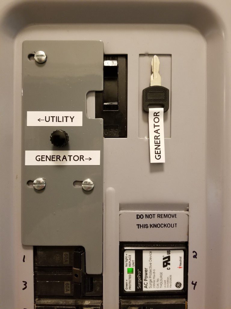
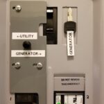
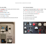
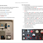
– Main Breaker Interlock: This is a sliding plate that mounts inside the existing main panel and it prevents the main breaker from being ON at the same time as another nearby breaker (and vice versa). The generator powers the main panel through the nearby breaker.
I opted for the Main Breaker Interlock since it’s allowed where I live and it’s the simplest way.
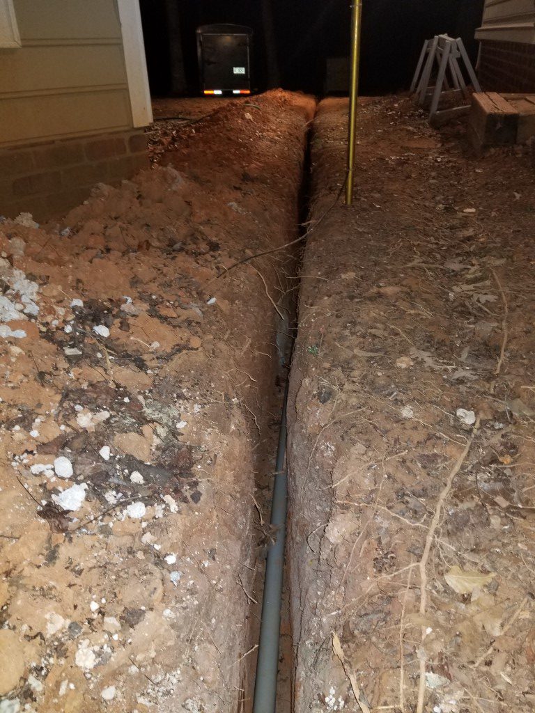
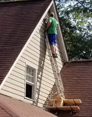
#3 – Running cable was the toughest part. Since the generator isn’t a residential unit that’s fire-rated to be directly next to the house (it probably would perform better than a residential unit, but the military doesn’t do the residential testing) it had to be at least 2ft away. 2ft away would have made for an awkward placement and it would have been in the way a lot, so instead I took it much farther out near the tree-line; leading to a ~60ft long trench. Code requires either 18″ of cover or 24″ of cover depending upon whether or not conduit is used. I opted to use conduit since the shallower trench saved digging effort and also reduced the chance of encountering any other utilities in the process. Most of the digging was through very dense/hard clay and it was slow-going with a trenching shovel. I welded the shovel back together at least a few times. I also experimented digging with the pressure washer, which mostly made a mess. The last 2ft near the house were through concrete; the technique I used for this was to turn the area into Swiss cheese with a hammer drill, break it out with a small air chisel, and then progress down to the next layer. I had been on and off of this effort over the past year and finally finished this weekend.

(#4) Misc things. Since the generator wasn’t originally intended for residential installation there were a few extra things I did to convert it:
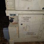
– I added cabinet locks to all of the access doors. This isn’t for security so much as it is to prevent anyone that shouldn’t be in there from getting into danger, especially the front door that has the output terminals directly behind it.
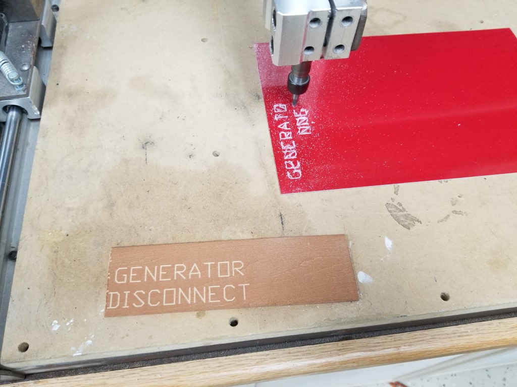
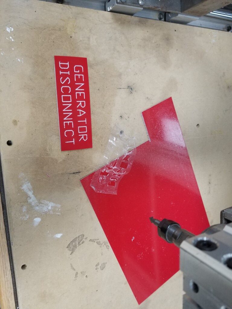
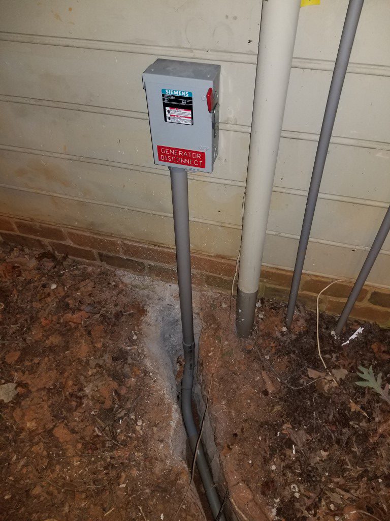
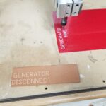
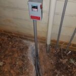
– One of the code requirements is that there must be a way to disconnect the generator outdoors. The generator itself sort-of/kind-of meets this requirement since it has a switch on the operator panel that will open the relay that connects the output power. Since this switch isn’t directly a disconnect though and since there’s a lock on the operator panel that could restrict access I also added a ‘real’ disconnect on the exterior of the house. I used the CNC router to make an engraved sign to mark it.

– Since the interlock completely disconnects the house from the utility it can be tough to know when power is restored. Electrically it would be possible to have a light/buzzer on the utility connections before the main, but since this wouldn’t have a breaker it wouldn’t be safe or code compliant. I found a device that’s made exactly for this problem and installed it. It has it’s own power via a 9V battery and has an antenna that wraps around the line from the utility to monitor power status. The alarm is armed manually when on generator power and as soon as utility power returns its siren sounds.
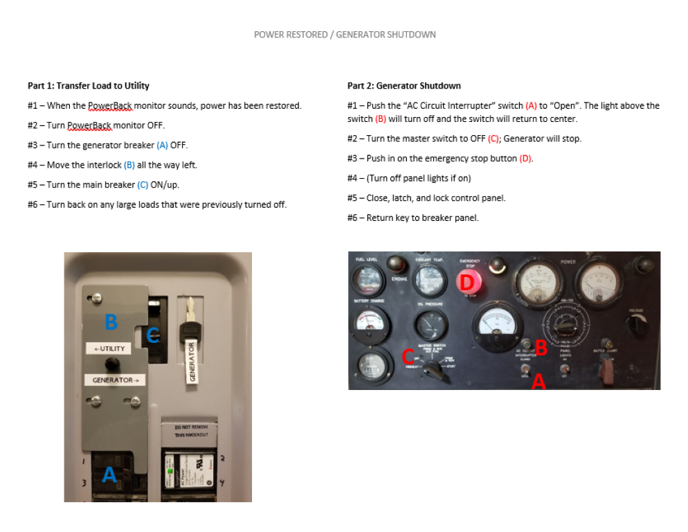
– I made a step-by-step instruction list with photos so anyone that’s home at the time of a power outage can start the generator and operate the interlock. This list and the key to the generator are held inside the main panel with magnets.
Next step is to get it inspected and then I can backfill the trench and clean the mud off of everything one last time.