Hacking the Player Piano – Part 1
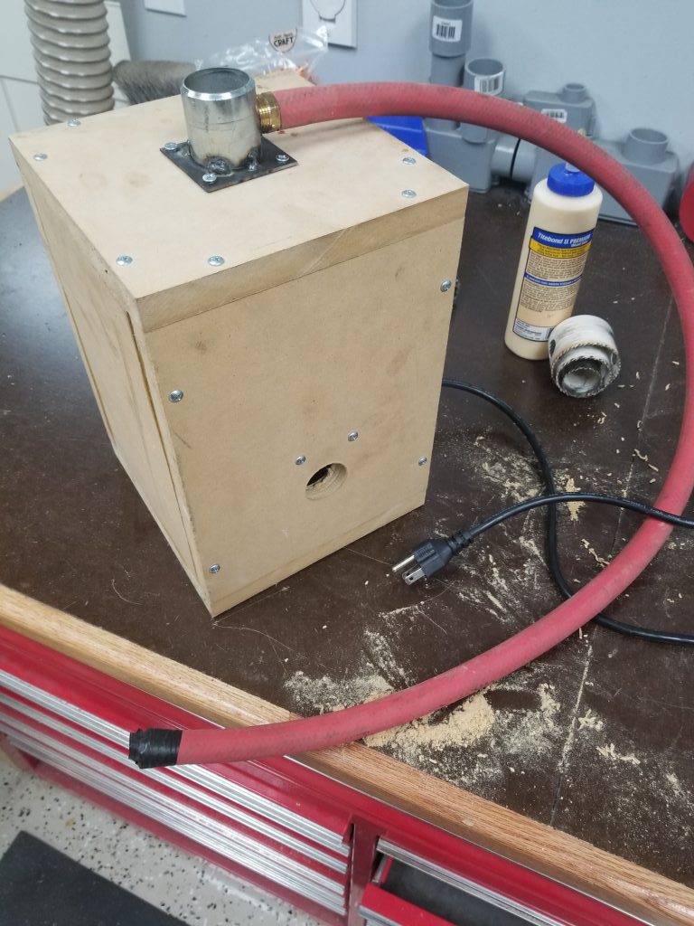
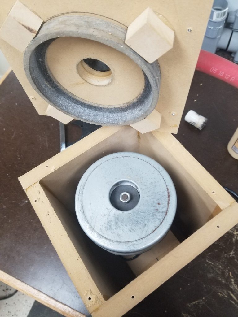
It was only a matter of time before this happened – the player piano (original post) is a real workout to play manually. Since it works on vacuum, I had set aside the motor from an old vacuum cleaner for potential use in powering the piano. Tonight I built a small box to contain the vacuum motor and connect it to the piano. The box is made from MDF, partly because I had scrap that needed to be used, and partly because it’s very heavy & sound absorbing. I made the big fitting by cutting/milling a square from scrap, I then bored a hole in it on the lathe and welded it to a scrap of pipe.
One very large hose goes to the manifold powering all the key bellows, and another smaller hose powers the vacuum motor for the tracker/scroll mechanism. I didn’t notice the smaller connection at first, so I had to go back and tap a fitting into the connection for the large hose; there’s still enough room for both to connect though.
Overall it seems to work great, this effort was definitely a quick proof-of-concept though and I’ll need to go back and fix/test a few things:
#1 – Motor controller to slow down the vacuum motor. Currently it has way more vacuum than is actually needed and slowing down should reduce noise from the motor.
#2 – Ensure cooling is OK. Especially after slowing the motor down I need to test that air flow is good enough to keep the motor consistently cool.
#3 – Mount in piano base and complete further noise insulation.
#4 – Tee hoses (and potentially add check valves) so that manual operation still works.
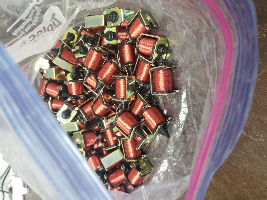
Beyond that I do have plans to eventually (could be tomorrow, could be in 5yrs) automate the player mechanism using some small pneumatic solenoids I found on ebay. These would tee off of each line from the tracker bar and when they open it would simulate a hole in the paper passing by. With this it would then be computer controlled and able to play anything. By default these are off/closed, so the paper mechanism would still work fine, in computer-controlled mode I’d just need to block off the tracker bar holes with some tape.

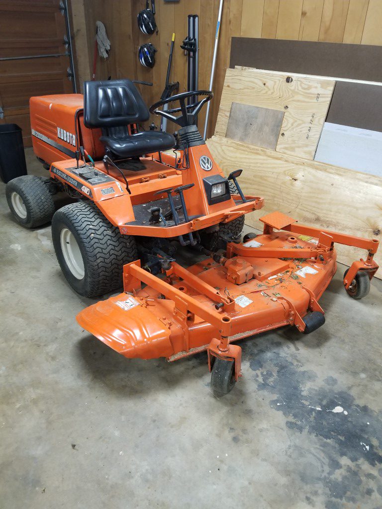
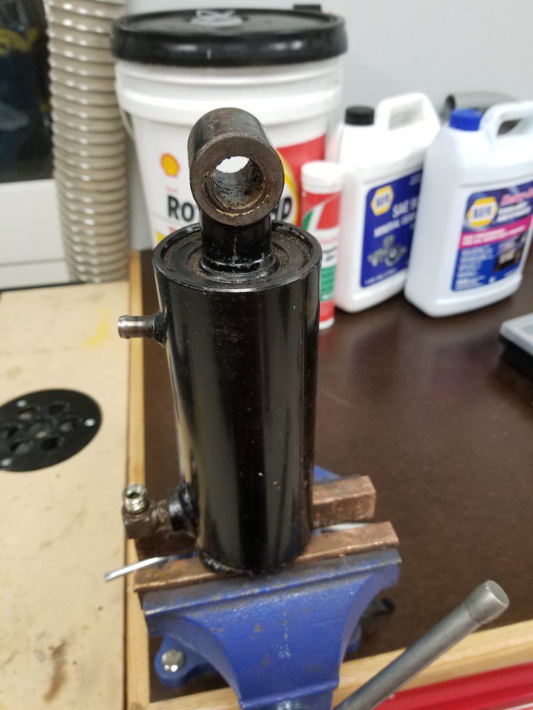
Kubota F2000 Lift Cylinder Re-Seal
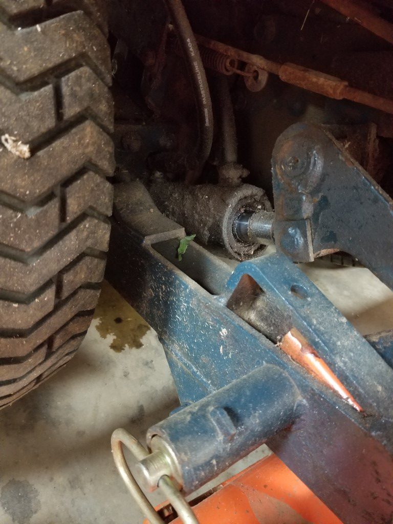
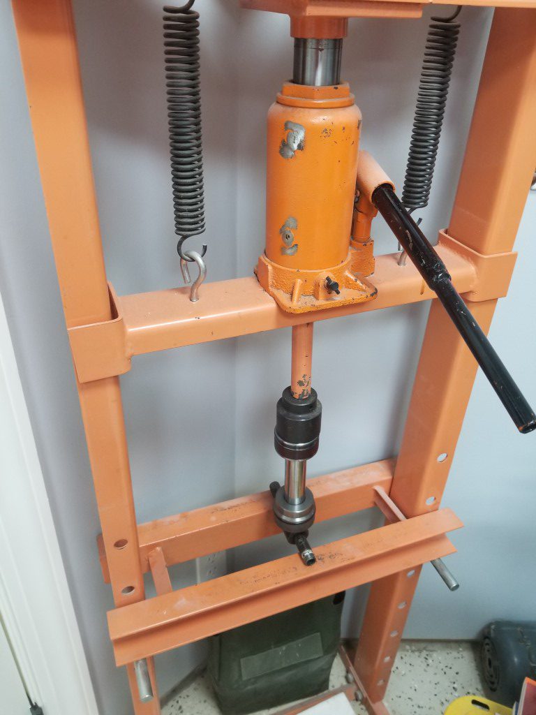
Tonight I rebuilt a leaking hydraulic cylinder on the mower. The leak was coming from the scraper/seal that seals the rod to the end of the cylinder. Unfortunately since the end of the rod is larger than the seal, the cylinder has to be disassembled to replace it. The process went as follows:
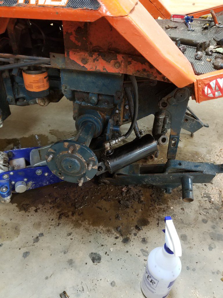
#1 – Remove cylinder from mower.
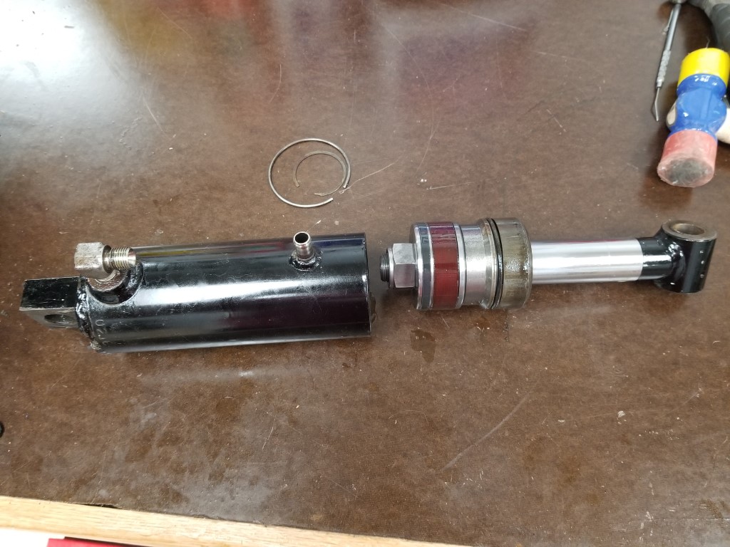
#2 – Remove the internal cir-clip that holds the cylinder end inside the cylinder bore. This was extremely fiddly and took 20min or so with dental picks and small screwdrivers to get the end of the clip pulled out.
#3 – Remove the cylinder end and piston/rod from the cylinder bore. The cylinder end’s O-ring catches on the cylinder’s cir-clip groove, so while it moves freely to a position that’s ‘almost’ out of the bore the last bit of movement requires clamping the rod in place and persuading the cylinder downwards with a hammer.
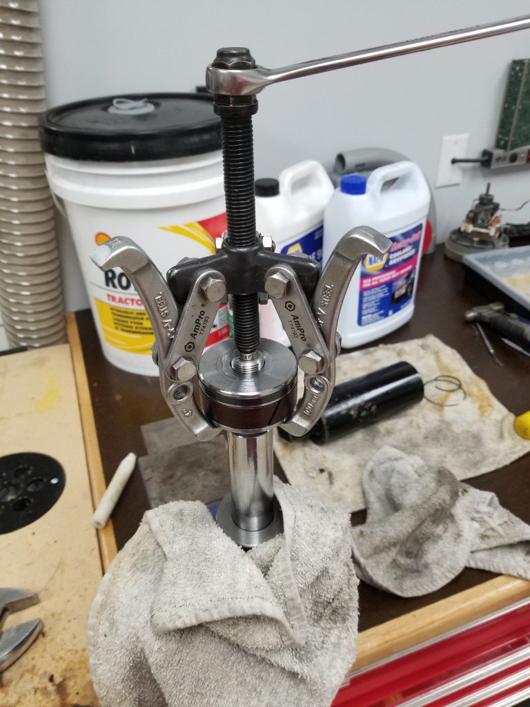
#4 – With the piston/rod/end removed from the cylinder, the nut can be loosened and the piston removed. The piston is a press fit and requires a gear puller to remove and a hydraulic press to reinstall.
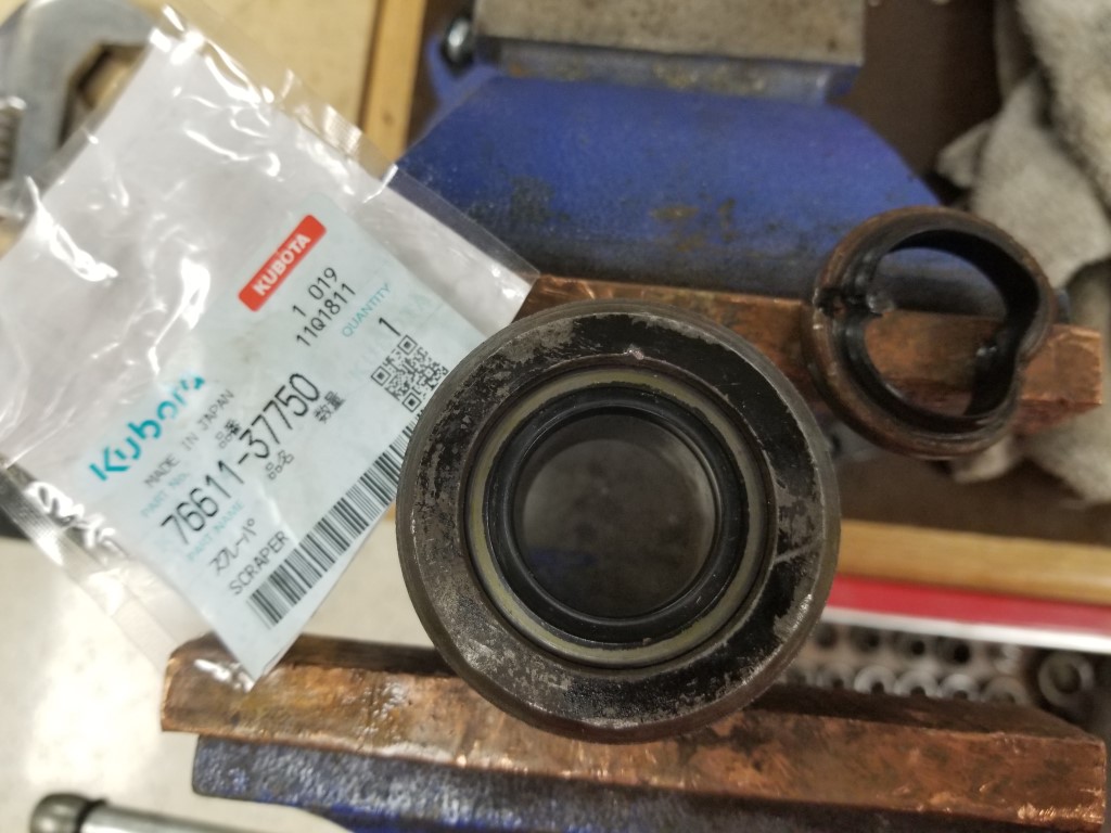
#5 – With the piston removed the cylinder end slides off of the rod and the scraper/seal can be replaced. The scraper has it’s own small cir-clip that’s much easier to remove.
#6 – Re-assembly is the opposite of assembly, while I was at it I also replaced the cylinder end O-Ring.
#7 – Reinstall
After the rebuild the mower no longer has any hydraulic leaks; the last remaining leak is an engine oil leak that I’ll be tracking down next…
Piano!
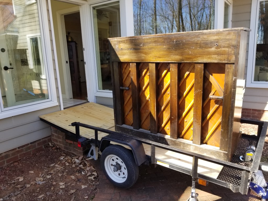
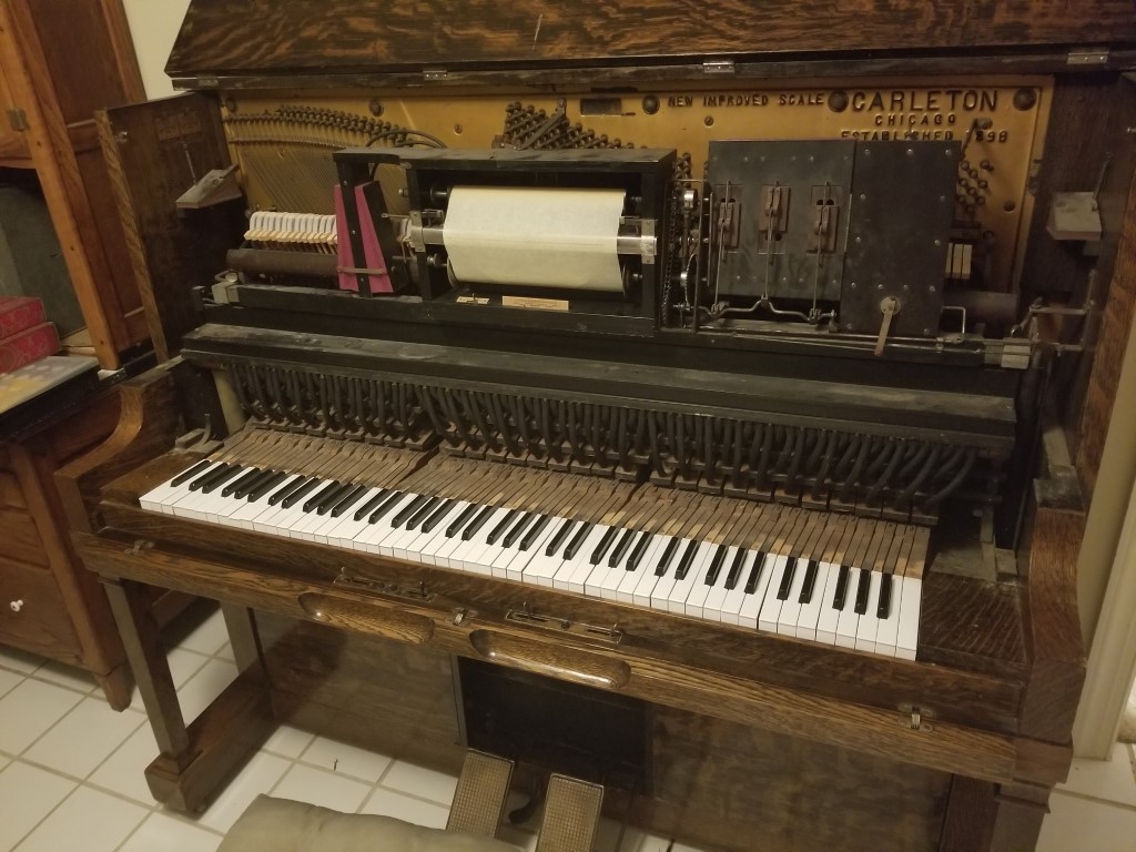
Christina has had an eye out for a piano for a while. Interestingly the standard price for used pianos is ‘free, must be able to move’. With this in mind we were shopping on ease of moving – looking at the surroundings in the listing photos to determine where it likely was (i.e. garage vs inside) was almost as important as the piano itself. The right one popped up this week, so this weekend we took the trip to pick it up. I had a particular interest in this one also since it’s a player piano. Player pianos are one of the earliest (the earliest?) wide-spread programmable automated ‘machines’; it’s fascinating to see how these were designed to be built using mostly hand-made parts and to operate without electricity.
Moving: Pianos are the archetype of things that are difficult to move. The trick, as usual, is letting the equipment/physics do the work. At the pickup side it was already in a garage; after backing up near it I jacked the tongue of the trailer up so the ramp/bed formed an even & shallow slope. I was ready with the winch at this point, but because their driveway sloped away it actually rolled onto the trailer without needing it. To unload, I backed the trailer around the back of the house to the back door and then raised it up on jack stands until it was about even with the threshold. We then put a 4×4 timber across the bottom of door frame of a nearby interior door and used this as an anchor point to winch the piano inside with ratchet straps. Once it landed on the tile floor it was easy to push around.
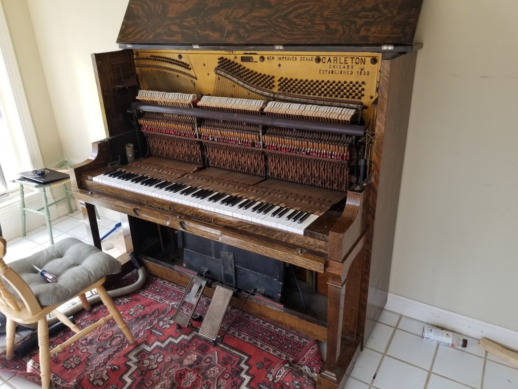
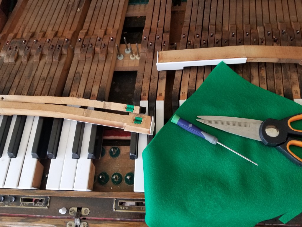
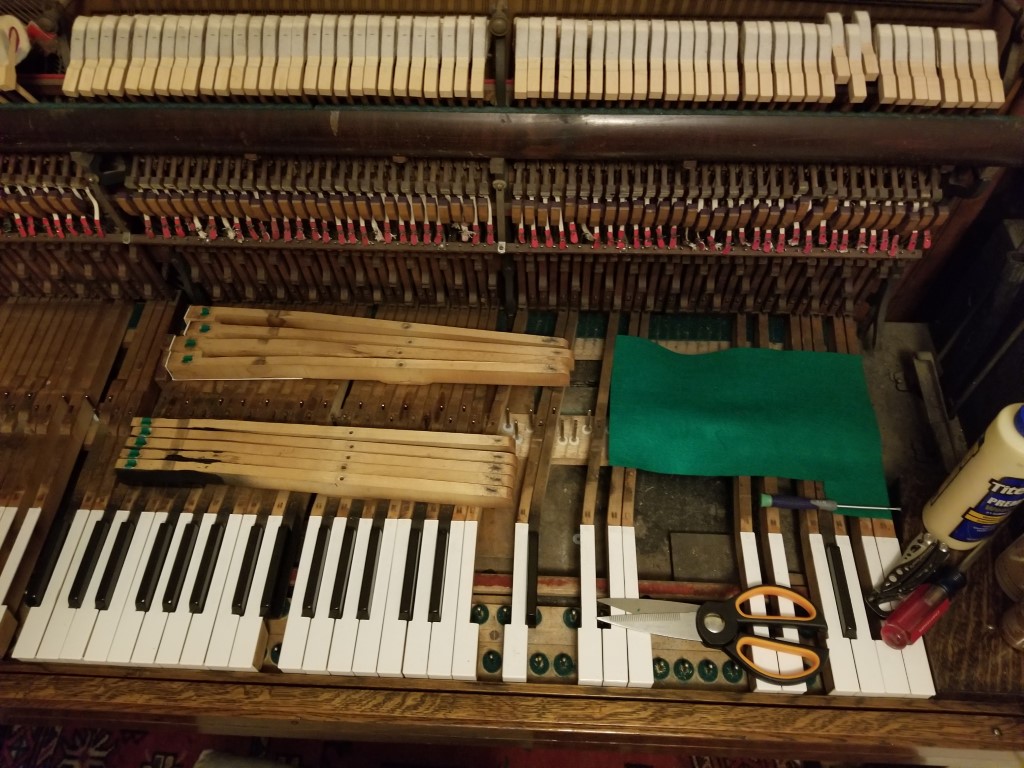
Rebuild: As near as we can tell from the serial number the piano seems to have been built in 1920. It was also signed inside with a 1996 date, likely associated with a rebuild. The good news is that everything seems to be in place and after sealing a few vacuum leaks it was able to play automatically; It definitely had/has room for improvement though. I was able to make it sound noticeably cleaner by dialing in the correct ‘capstan’ height on the back of the keys. The next priority is getting the keys working more consistently; several of the keys (~40) were missing felt from their front hole. The front hole felt prevents the key from wobbling side-to-side. Several keys (~20) also had cracks where the back hole goes through the key. The back hole is where the key pivots, so these cracks allowed the keys to tilt side-to-side. Felt was added to the front holes and the cracked back hole parts were glued back in place; this resolved the loose key problems. For just a few keys (3) the cracked part is missing and I’ll need to create and glue in a repair piece. Once I’m finished rebuilding the keys I can then go through and set the key level and adjust the hammer action. Along the way I’ll also be coming up with an electric vacuum pump – pumping with the pedals is a work out!


Security Lug Defeated
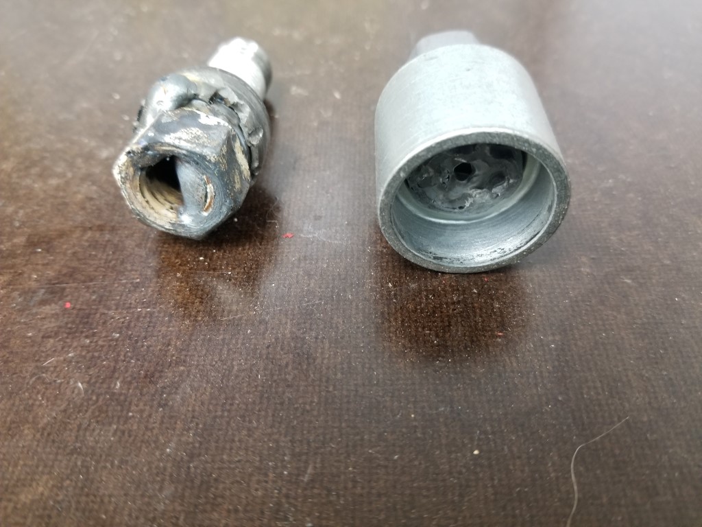
This week’s challenge was a flat tire; I switched to the spare relatively quickly and uneventfully except that when I was tightening the security lug bolt the security key slipped out a bit. When it slipped it broke a little chunk off of the security key and warped the security pattern on the lug bolt. I ordered a new key and lug right away but since I didn’t want to risk the warped lug bolt breaking the new key, I had to come up with some other way to remove it.
First I tried a broken lug extractor – these are cheap and readily available at the local car parts place. They’re basically a regular impact socket with a reverse thread on the inside rather than the usual hex pattern. The theory is that as you loosen the lug the socket’s threads bite into and turn the lug bolt. This actually would have worked great if it weren’t for a collar that’s integrated into the security bolt – the socket only bit into this collar and it spun on the lug bolt without turning the bolt body. It’s almost like they thought of this scenario when the security lug was designed…
Next I tried to cut some small grooves in the bolt head and deform the collar into these grooves so that the collar would be able to drive the bolt out. I think this was an OK idea, but since the collar was glass-hard steel it chipped instead of deforming.
Running out of options, I decided just to weld a nut to the security lug bolt and unbolt it. I had held off on this ‘nuclear option’ because there is a level of risk – the ground current could actually weld the bolt into the hub somewhat or damage bearings/electronics – I chose the ground clamp location carefully and also cleaned it carefully to avoid this. It was a messy weld (prioritizing not damaging the spare) but worked great. I think the heat from welding may also have helped by expanding the bolt and relieving some of the pressure against the spare.
With the lug bolt out the spare was swapped to the (now repaired) wheel and tire. Not sure how a dealer/mechanic would handle this scenario, but I’m guessing it means the welder has now paid for itself for at least the 3rd or 4th time.
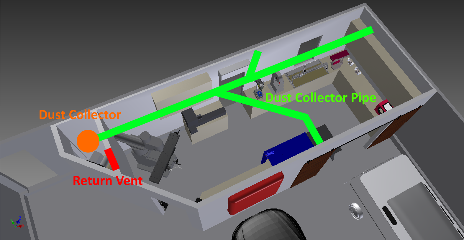
Dust Collection
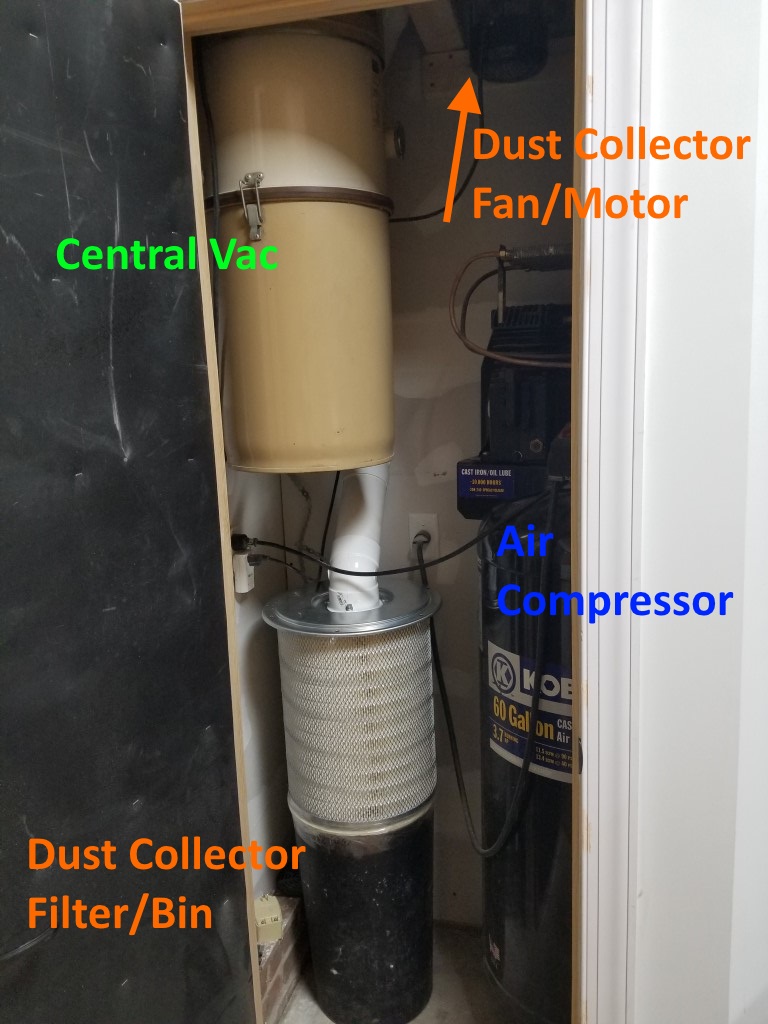
This weekend I installed the shop dust collection system. The system consists of several parts:
Fan/Motor: I repurposed a portable dust collector fan I’ve had for a while that’s been underutilized (collecting dust, but not as intended). Space is limited in the mechanical room so since the fan won’t need easy access I mounted it high up above the air compressor near where the dust collector pipe enters the mechanical room.
Pipes: 4″ PVC DWV pipes; there are a few branches leading to the different tools. I tried to keep the overall length as short as possible and the bend radius’s large.
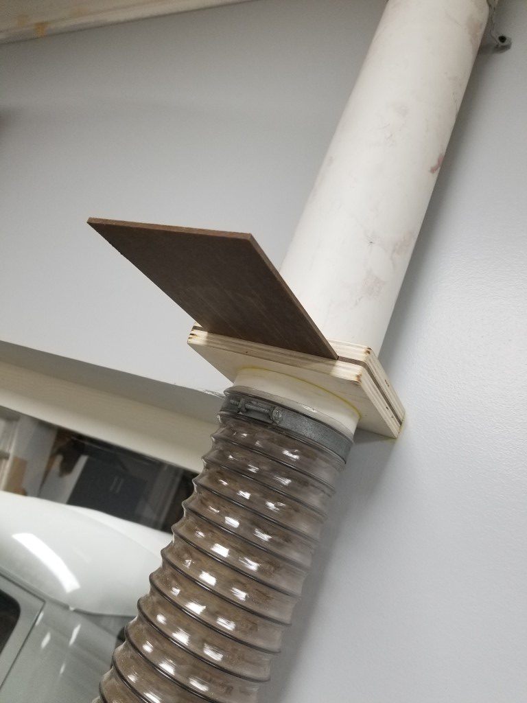
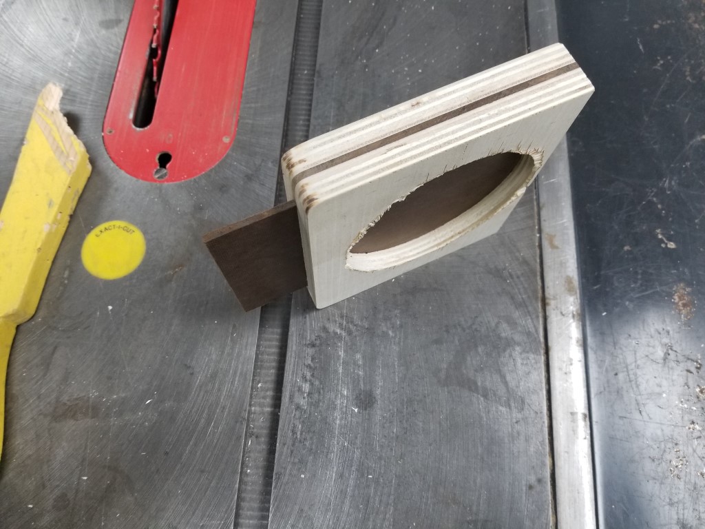
Blast Gates: The blast gates control the air flow though the system by blocking off unused branches. I made these with 1/2″ plywood and 1/4″ hardboard. Circle cutouts were made on the lathe to match the pipe outside diameter exactly.

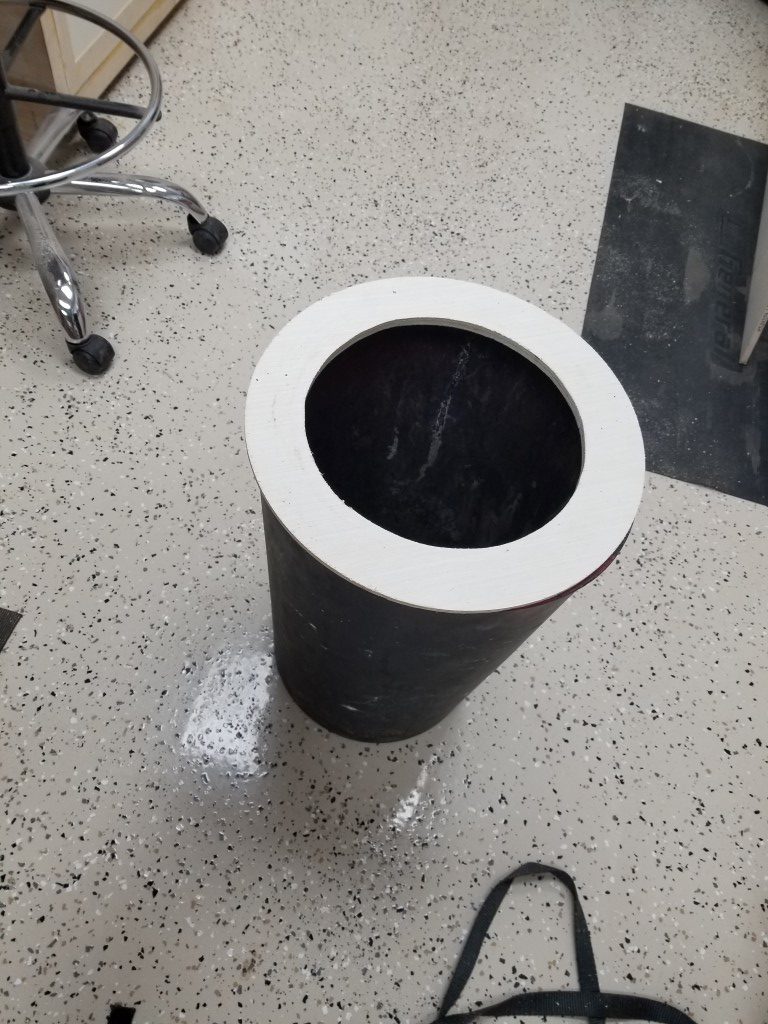
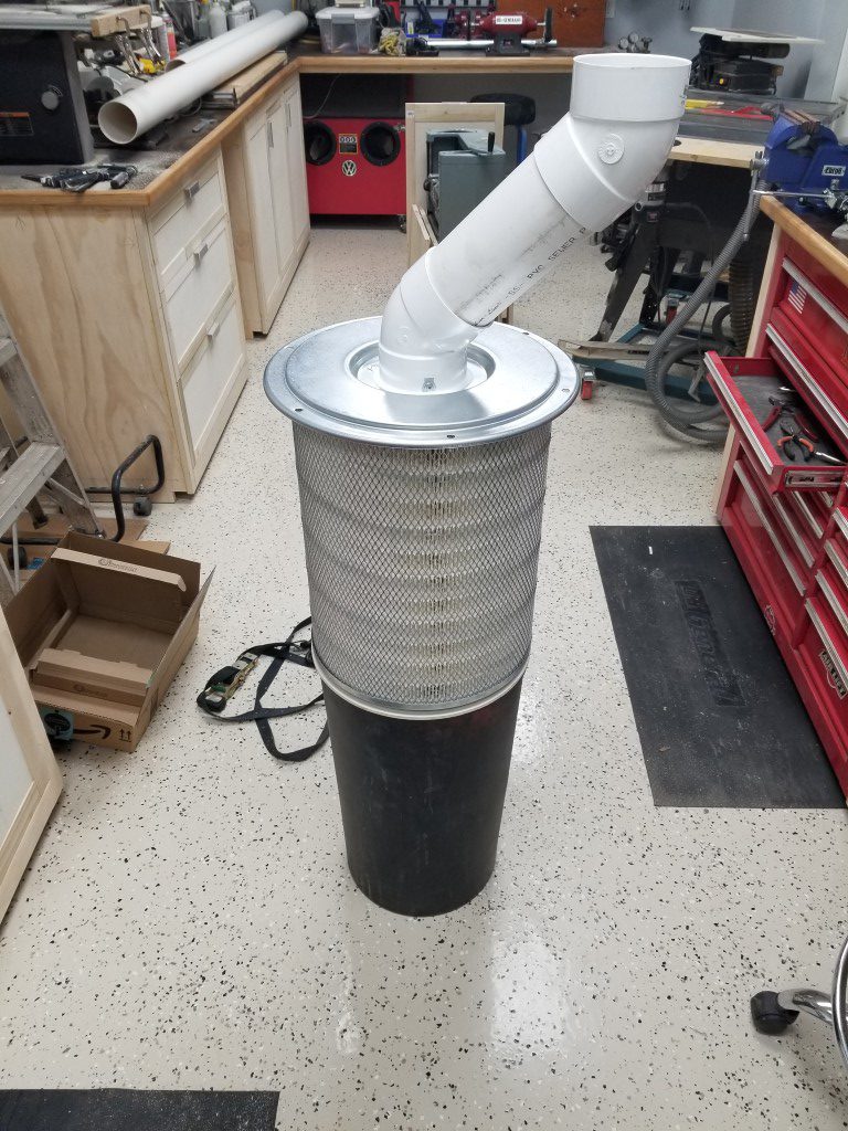
Filter and Collection Bin: The portable dust collector came with a light canvas bag that restricted the air flow massively while still allowing fine particles to escape. To improve this I replaced the bag with a semi truck air filter mounted to a trash can. The theory is that air will exit the filter and larger dust/chips should fall into the trash can below. There are purpose-built dust collection filters available, but the costs are much higher for these and the semi truck filter has the same specs; different economies of scale. To mount the filter to the bin I made a plywood ring, for now they’re just taped together but I may add latches at some point. The design may need some tweaking; I’ll know more after it gets further use, but for now the airflow is excellent.
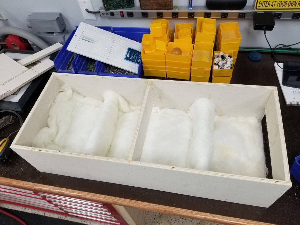
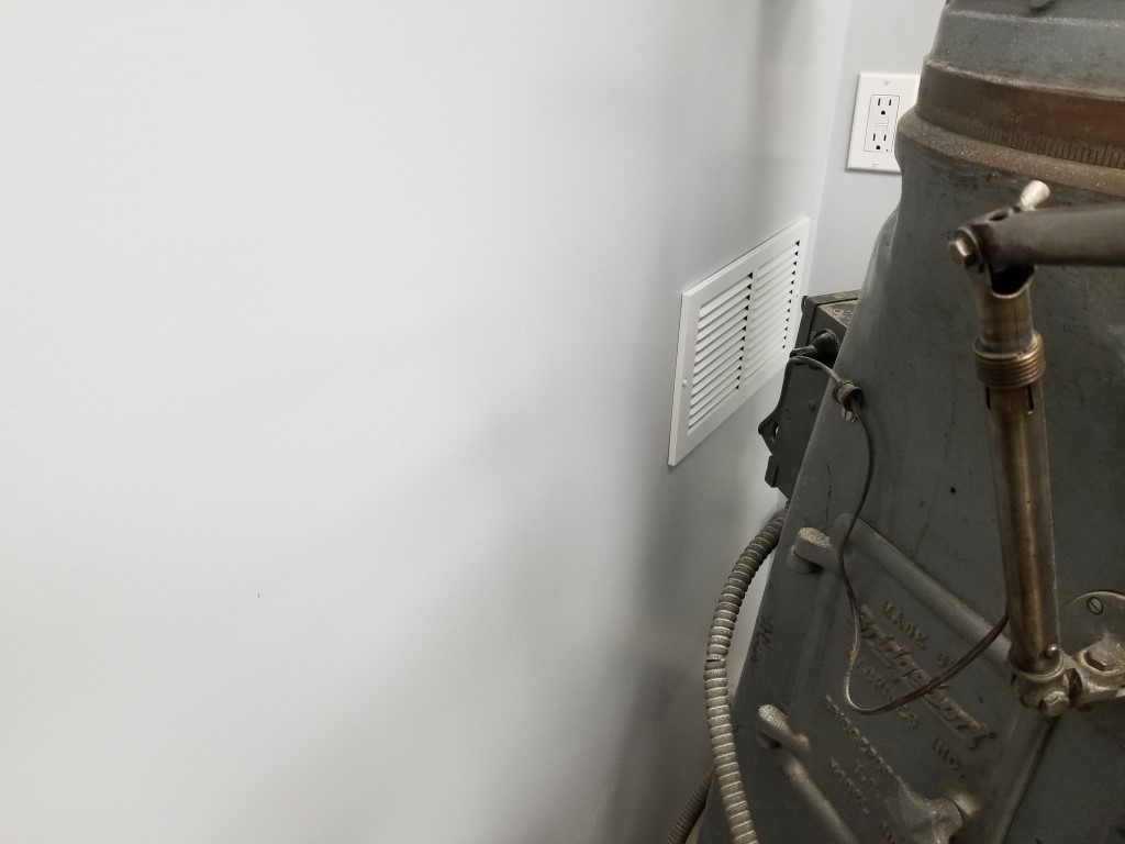
Return Vent: Having the collection bin in the mechanical room created a problem; the mechanical room is well sealed for noise reduction, so there was nowhere for the air exhausted from the filter to go. For heat/air to be retained in the shop, the exhaust air needed to return to the shop via a vent. Since I also wanted to keep the mechanical room noise level as low as possible this meant the vent needed to be sound proof. I built a sound proof vent by creating a 3ft long box and offsetting baffle plates inside of it. The sound has to reflect a dozen or more times off of the baffle plates; at each reflection it gets absorbed some by a fiberglass lining. The air, however, is able to snake around the baffles and find its way out. The inlet to this vent also points directly at the floor away from the sound sources. Somehow after adding this vent the mechanical room noise is actually noticeably quieter than when it was completely sealed. I think this may have had to do with the air pressure changes resonating in the previously sealed room, whereas now any fluctuations are equalized through the vent.
Control: For now control of the system is via a remote control outlet (repurposed from controlling the vacuum at the old shop), at some point I may integrate some low voltage switches with the blast gates so the motor will turn on as soon as any gate is opened.
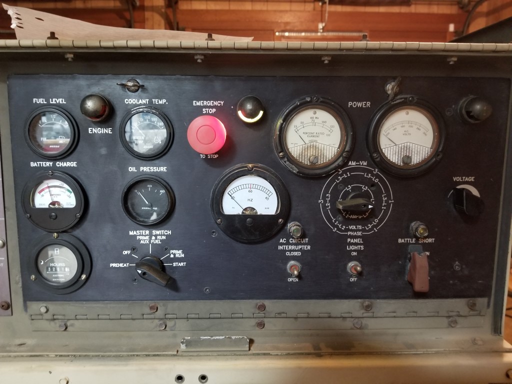
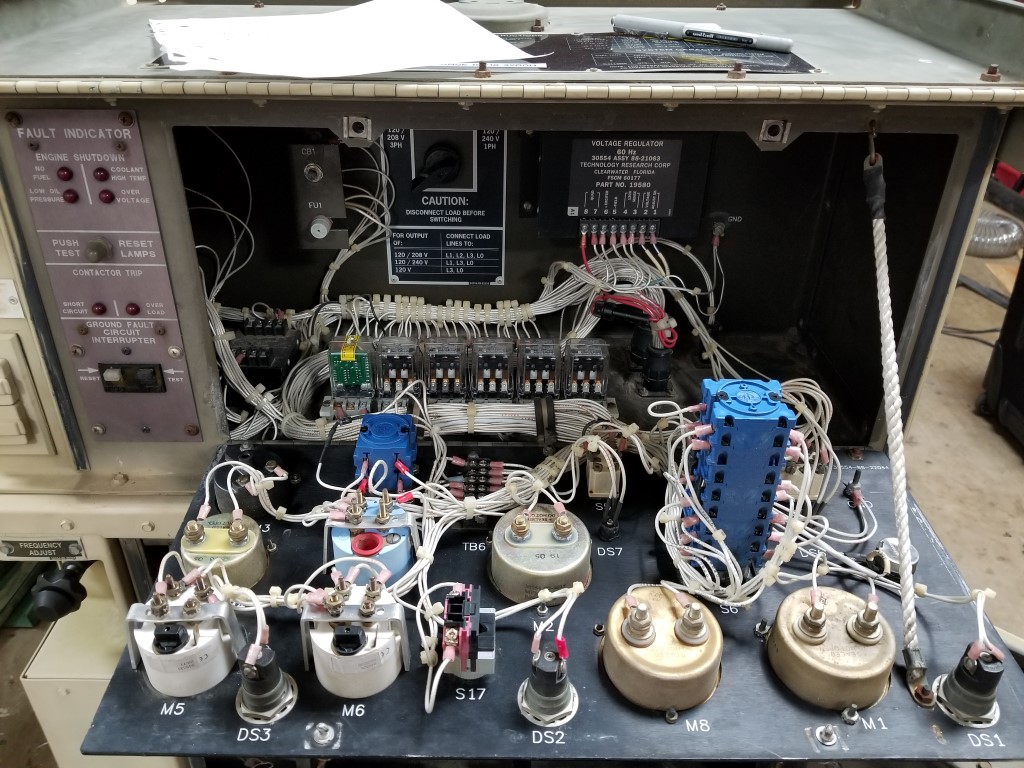
Generator Rebuild
Hurricane Michael hit our area hard and took out power for almost 5 days. Luckily the small generator we already had was enough to keep the fridge running and some lights on, but not much else. The small generator is 120V only, so it also was not able to power the 240V well pump; 4 nights without running water was not fun. It’s not likely we’ll have another outage that’s this long for a while, but we have had a number of shorter outages that seem to indicate that this will be an ongoing problem – a bigger generator would be nice.
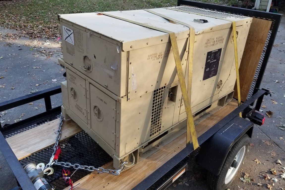
With that in mind we started looking at options; there are a number of ‘off the shelf’ options out there for whole-house standby power, but most of them are very pricey both to install and to run (propane particularly) and we couldn’t justify the cost for something that gets used so infrequently. What did seem to make some sense though was rolling the dice a surplus military generator; the prices are very low (when the condition is unknown), they’re way over-built, and are made to be repaired easily.
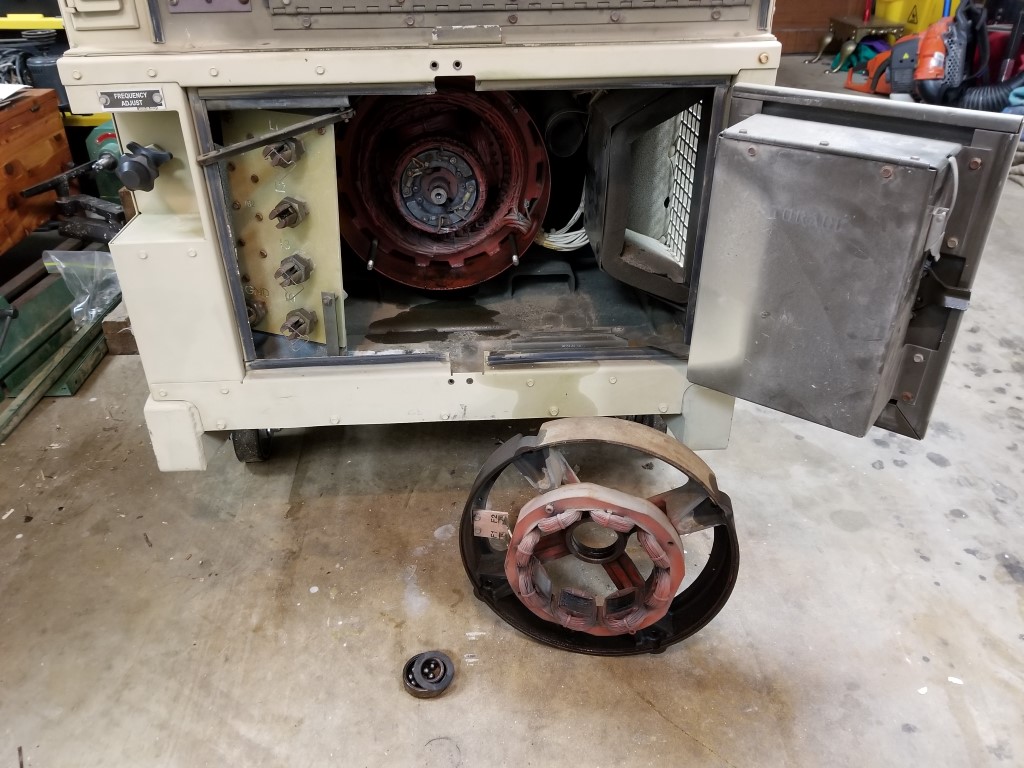
I bid on and won an online surplus auction for a diesel generator and picked it up outside our friendly neighborhood military base. It was a fairly easy move at ~1200lb; at pickup I just dragged it onto the trailer with a winch and to offload I tilted the trailer and winched it back down with iron pipes underneath as rollers.
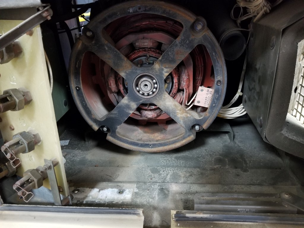
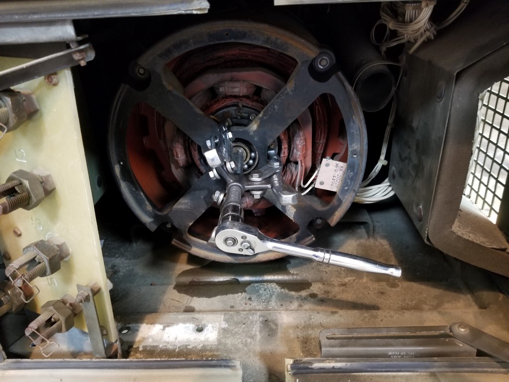
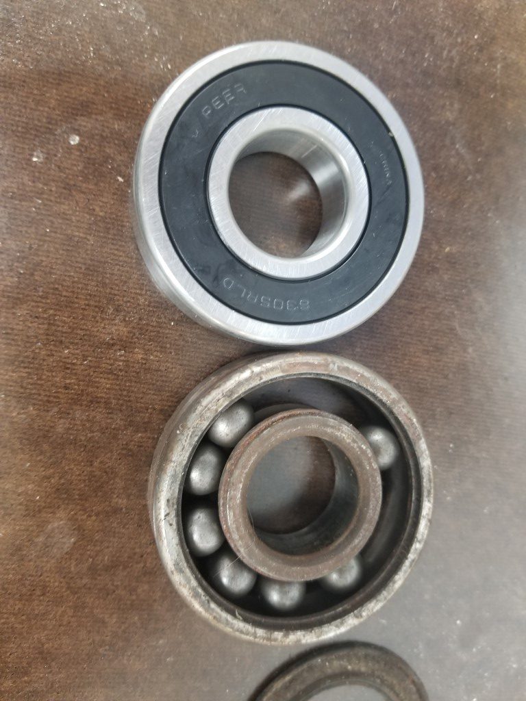
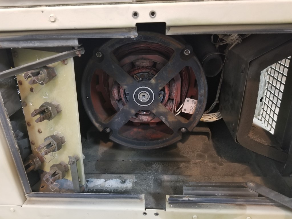
To get it running I first put in new batteries (2x 12v car batteries) and troubleshot some miscellaneous electrical issues (broken connections, dirty switch contacts, etc.). From there it would crank but not run; bleeding the air out out the fuel lines fixed this and it started OK. Once running there was an erratic low frequency rattle that I traced to a bad rotor bearing on the generator head. With this bearing replaced it then ran smooth/quiet. The last issue was twitchy voltage regulation that I traced back to a dirty potentiometer; with this cleaned it held a stable 240V @ 60hz under a variety of loads. Along the way it also got an oil/filter change and a coolant flush/fill.
Altogether this was a very quick project, just a few hours to get everything sorted out. Up next will be setting aside some space for it (probably combined with a new area for trashcans and firewood) and getting it wired in with a manual transfer switch. It’s a “10KW” generator but that rating is on the very conservative side; in reality it’s closer to a 15KW or more consumer unit whose ratings are on the optimistic side. This should be enough to run the lights, TV, well, microwave, and at least one zone of HVAC.
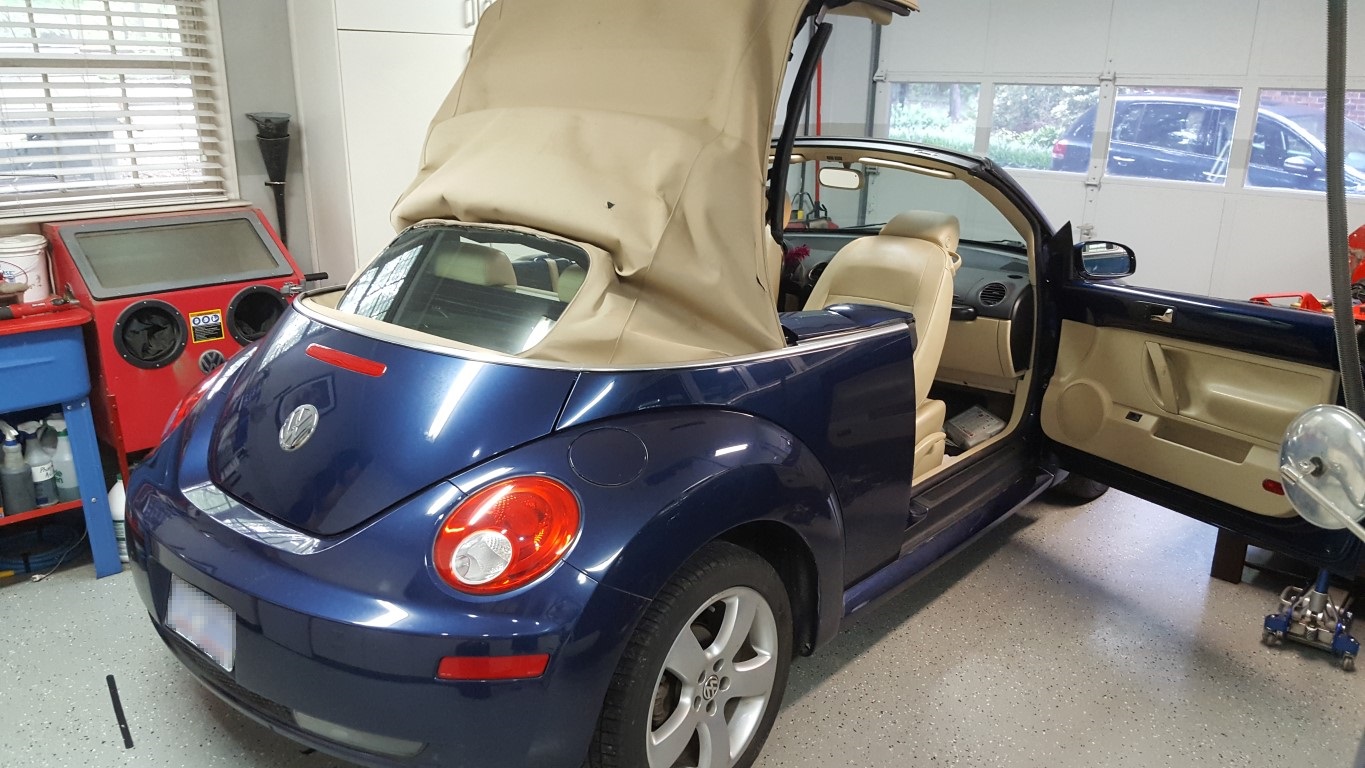
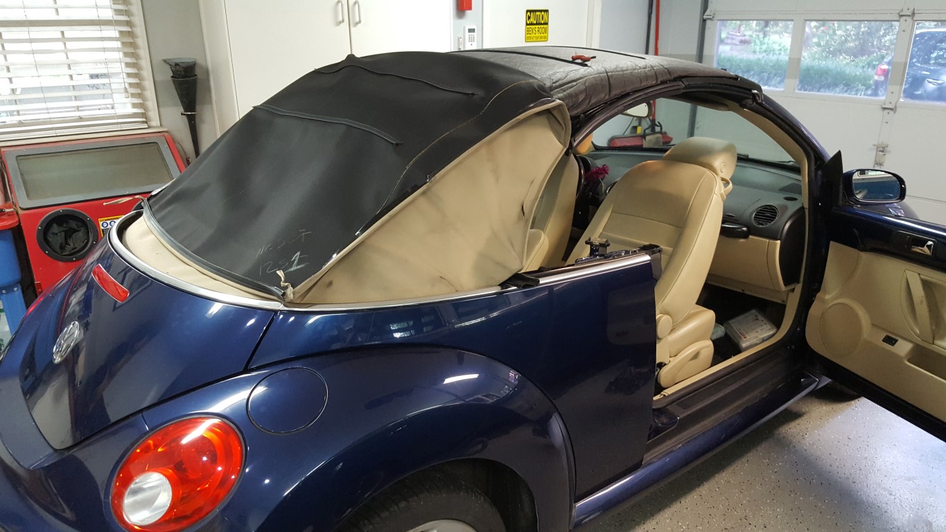
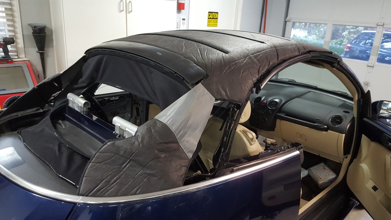
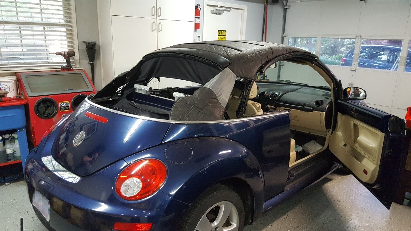
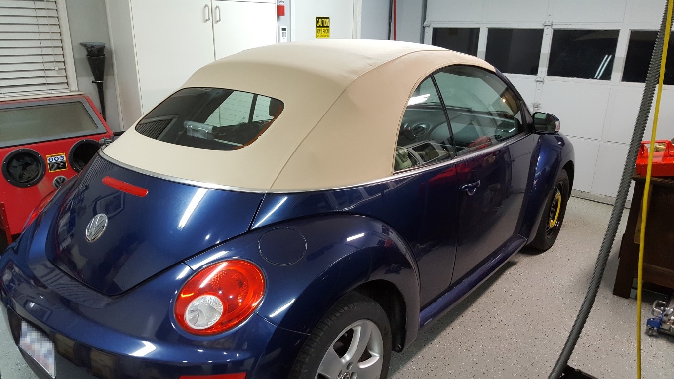
Converti-bug Top Replacement
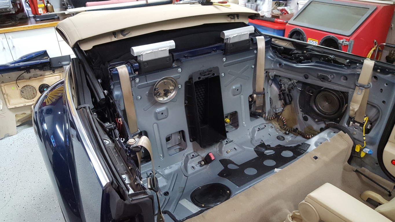
Last night and today we replaced the top on the Beetle. It was in ‘OK’ shape but was showing its age and the back window had begun separating/leaking, requiring roof replacement. Complexity level for this ranks right up there with an engine rebuild or debugging bad assembly code. The biggest challenge is that all the miscellaneous springs, ropes, and bungees involved don’t have the usual ‘this clearly bolts there’ pattern – instead it’s a spider web of cords that have to be routed just right, and their appearance changes greatly depending on how far up/down the roof is. With the help of lots of reference images though it all went back together correctly. Fortunately for modern tops like this there’s enough repeatably between cars that the tops come pre-cut with all the right seams/edges pre-made; there’s no trimming or other ‘upholstery’ type work that would be required on an older car.

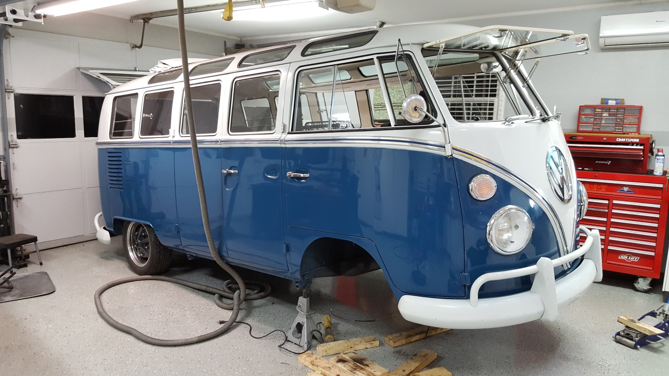
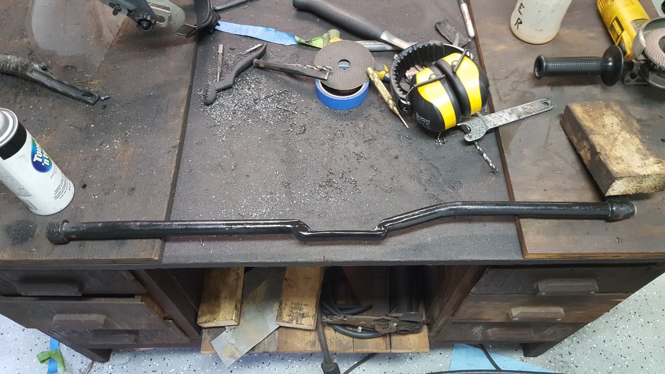
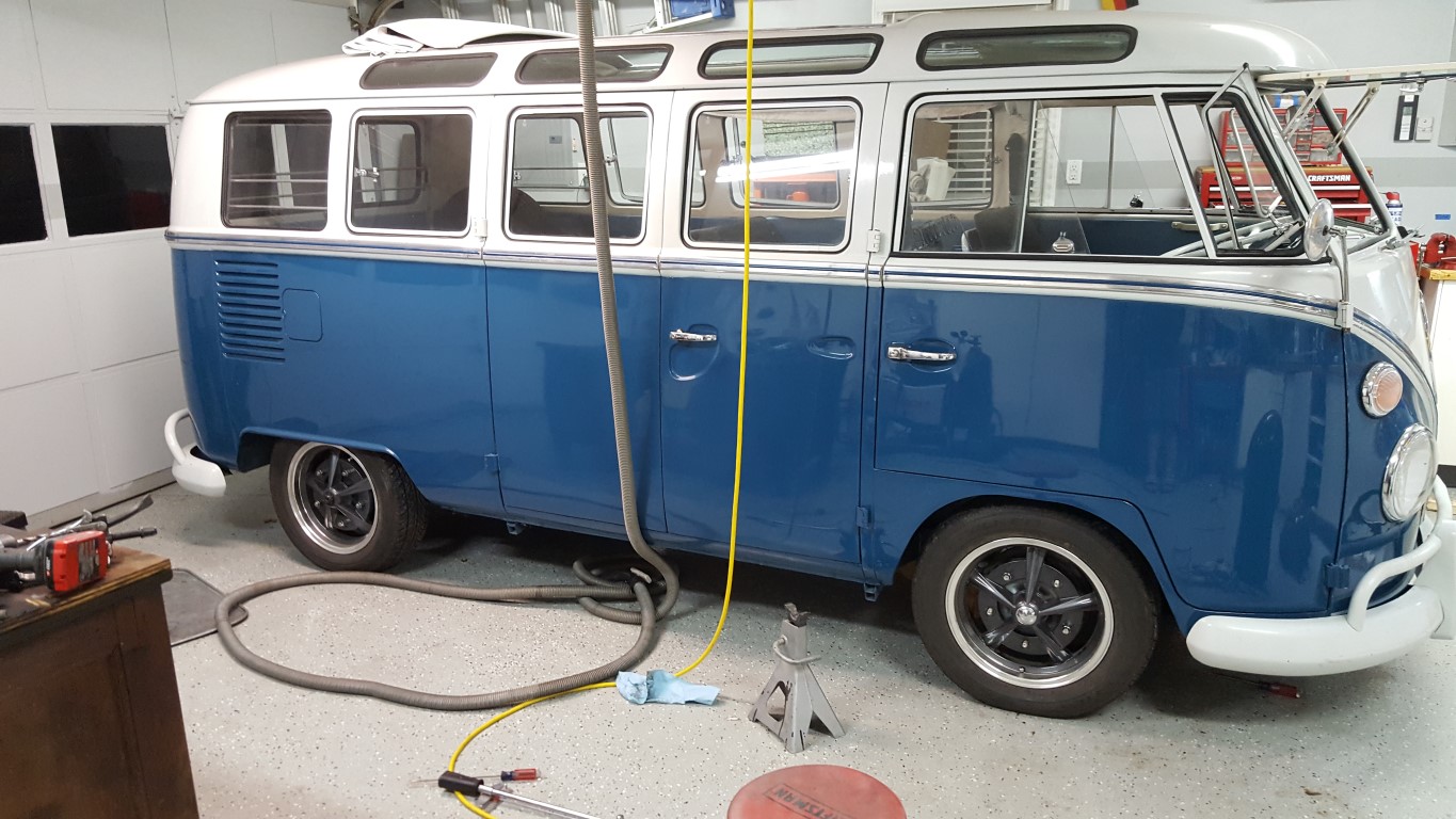
VW Bus Adjustable Front Beam
During the original bus rebuild I had ‘flipped’ the front spindles to lower it some. Stock height on buses was alarmingly high, lowering allowed for better handling and gave the possibility of the bus fitting in the garage with a roof rack. The spindle flip, however, lowers by a fixed 4-5″; just low enough that the front wheels would rub the wheel wells during bumps or heavy braking/cornering. Cornering was particularly exciting since the outside wheel would rub, slowing down that wheel with the tendency to make the turn tighter – or “positive feedback” for those of us that are into control systems (not a good thing).
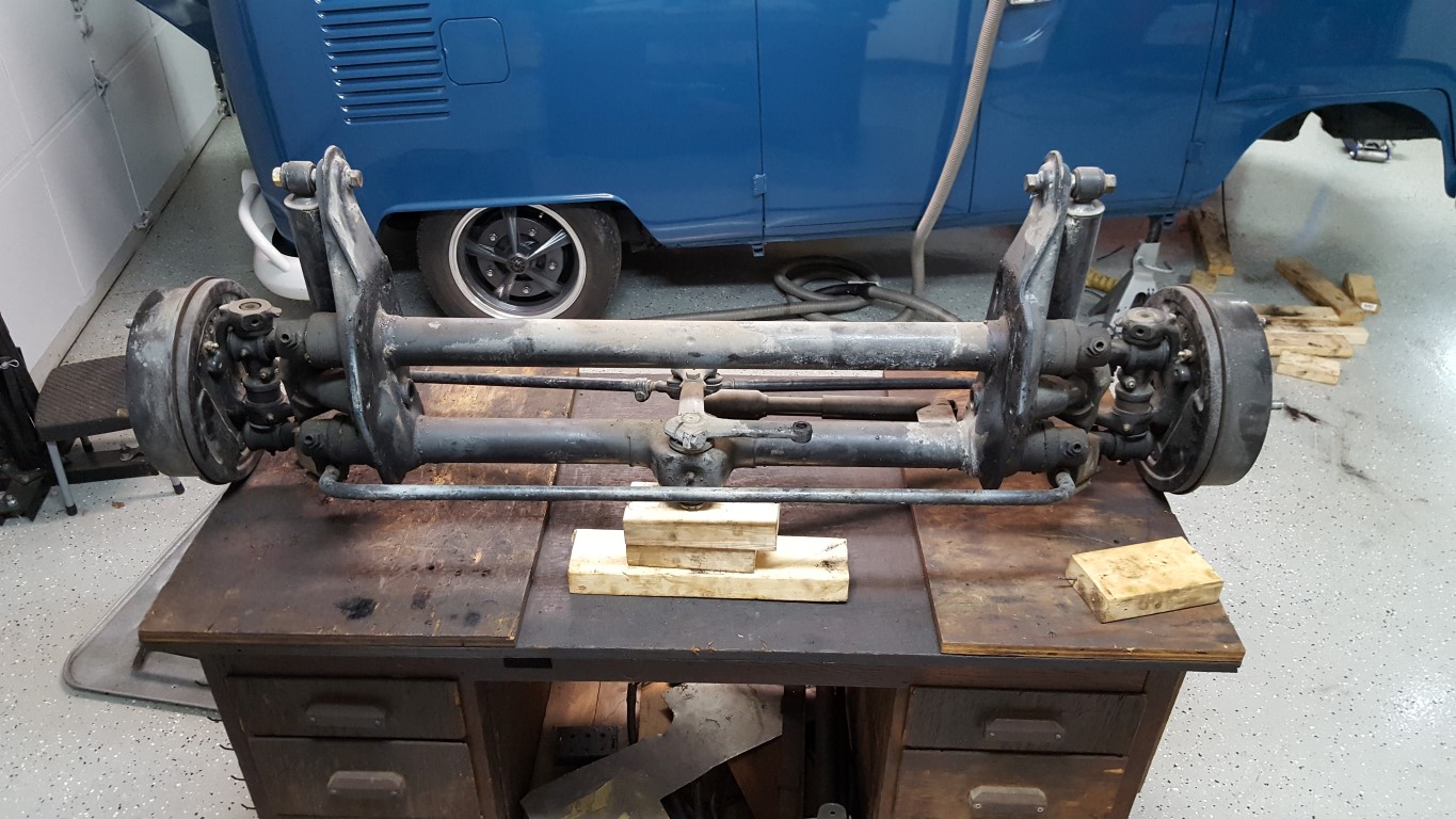
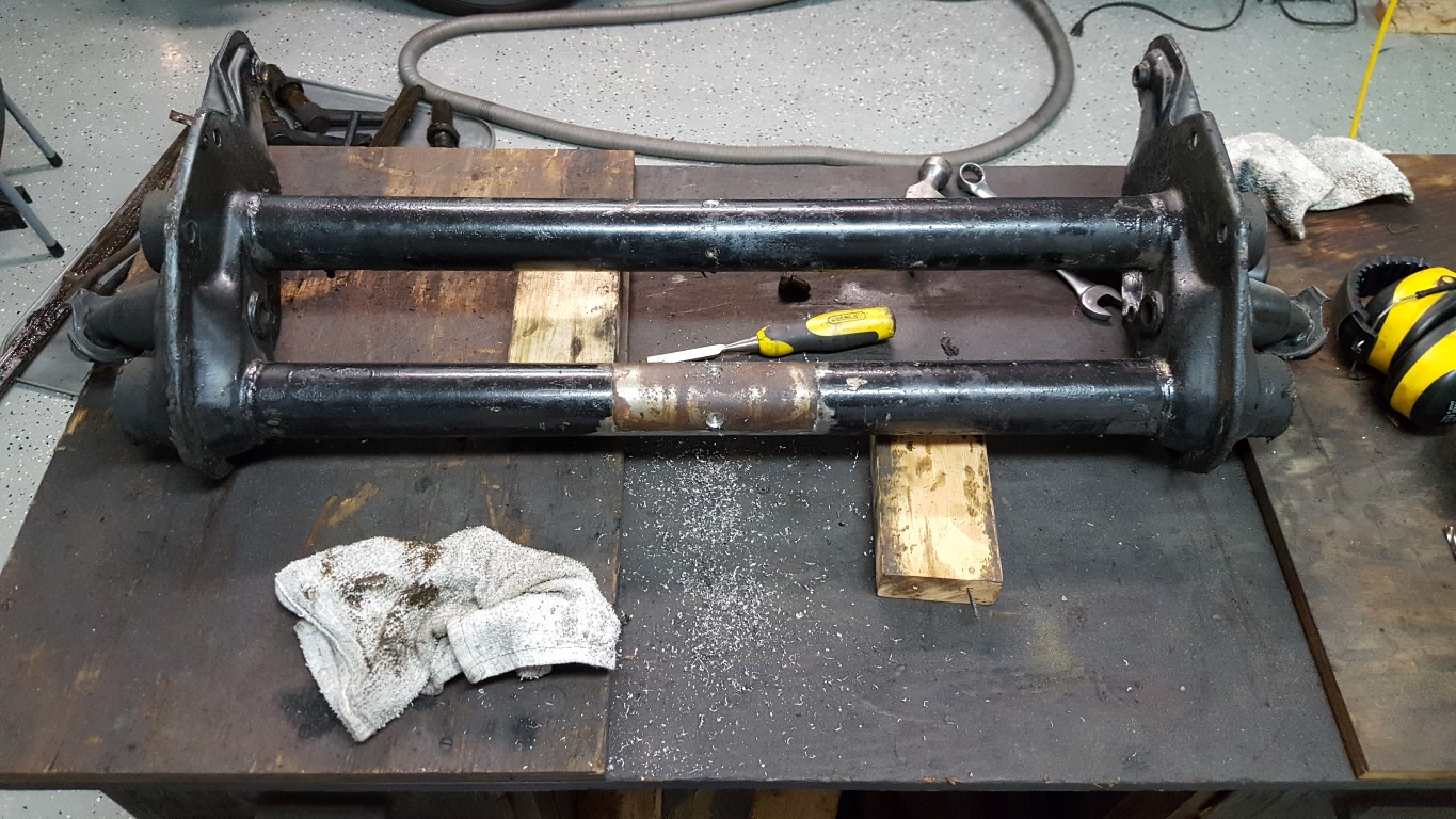
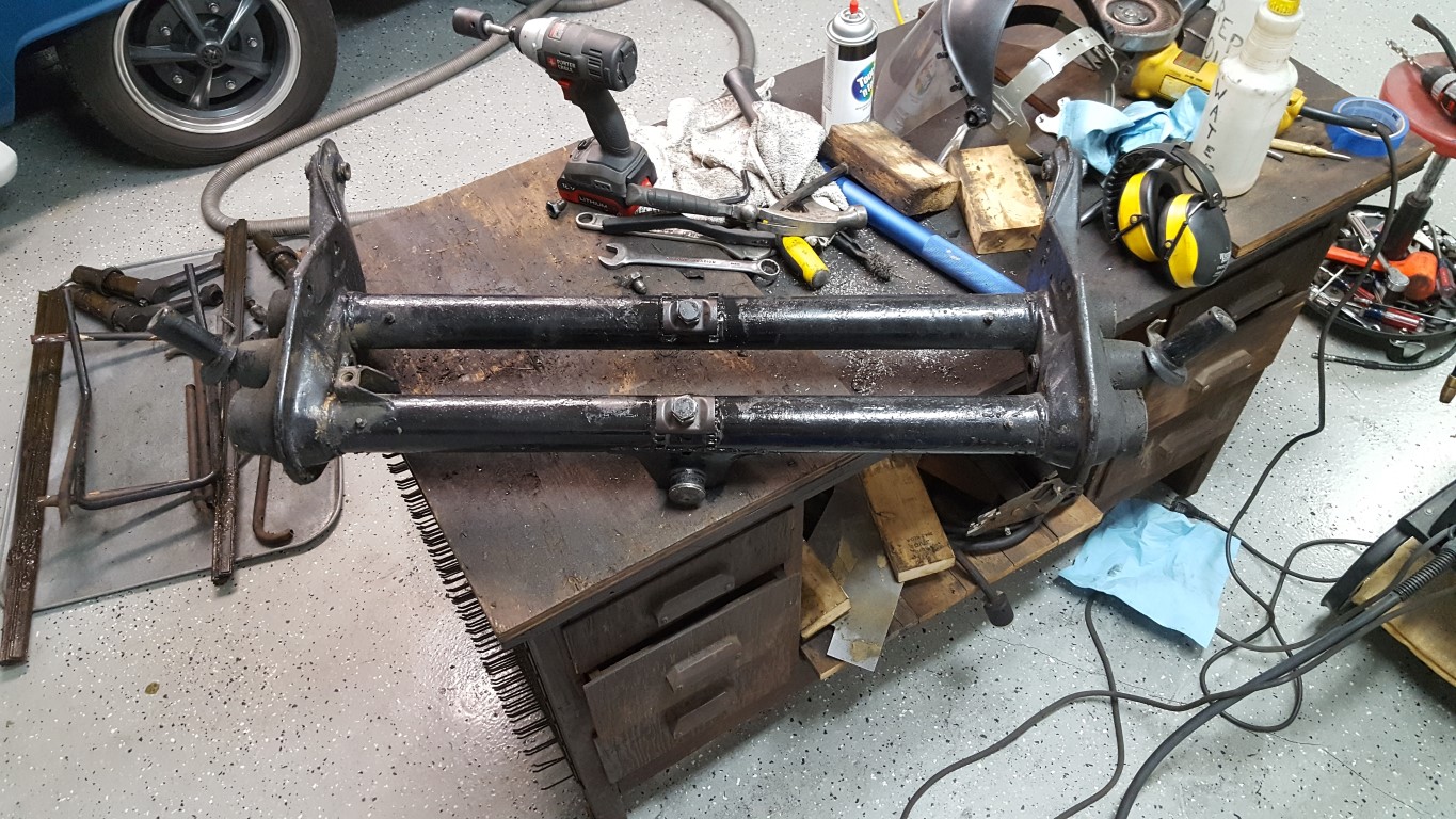
To remedy this, a way was needed to raise the front back up an inch or two. Old VW’s use a very unique front suspension design with two sets of torsion leaf springs inside of a beam with two tubes. The leaf spring packs are held fixed in the center of each tube and are capped at both ends with the four trailing arms. Minor raising and lowering can be accomplished by changing the angle the springs are held at the fixed center point. The center spring holder is held by divots crimped into the tube which engage with holes in the spring holder; these divots were drilled out which freed the holder. Toothed sections were then welded to the tubes; when the center is bolted in place a nut is tightened against a toothed plate that engages the teeth, holding the torsion spring pack at the new angle.
Lots of things had to be disconnected and then reconnected to get the beam in/out. This made it a greasy, awkward, and tedious job but overall it went well. The only hiccup was that after the beam was re-installed the shift linkage interfered with the adjuster bolts, though I had read this could happen. To solve this problem I welded a chunk of plate steel to the bottom of the linkage to hold the geometry and then ground out a strategic section of the linkage tube. The plate is as strong or stronger than the tube, and it’s in just the right spot to clear everything above/below it. After everything was back together the bus is level and no longer rubs the front wheels!